
Last Seen Blogs

lvii
crybaby
immrmongo
65 Ford Falcon Club Wagon Deluxe!

azzyg
❤️

xxjayflowerxx
Warrior Cats ✧ And Fanart

eggzumi
☾︎
Text
HOW DO PLANES FLY?
Wingardium Leviosa!! Not surprising, that’s not how planes fly although that would be cool. It was the Wright brothers in 1903 to build the first plane and now we have come a long way from 12 seconds to intercontinental flights now but the overall concept of equating forces and maintaining equilibrium is the same.
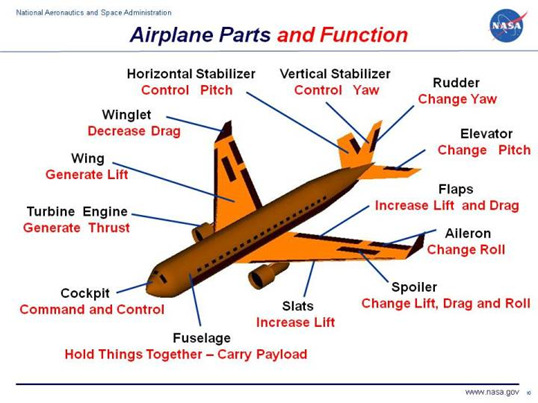
(Structure of a plane, source- https://www.grc.nasa.gov/www/k-12/airplane/airplane.html)
There are 4 forces acting on a plane the weight acting downwards, the lift(upwards) due to the pushing effect of wind on the plane, the thrust created by the turbine/propeller of the plane which helps moving the plane forward and opposing the thrust is the drag force which is produced by the fluid(air) on any object moving through it.
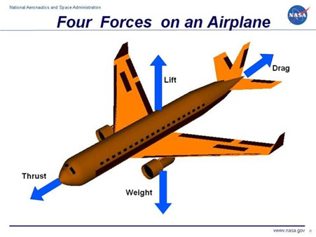
(forces acting on a plane, sources- https://www.grc.nasa.gov/www/k-12/airplane/forces.html)
In a balanced flight, all the forces, cancel each other out and the plane is in equilibrium.
AIRFOIL
The cross-sectional shape of the wing is called an airfoil.
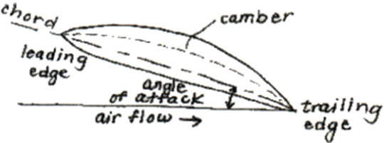
(Structure of an airfoil; source- https://web.mit.edu/2.972/www/reports/airfoil/airfoil.html)
Chord: line joining the leading and trailing edge
Camber Line: halfway between camber and upper wing surface
Angle of attack: Angle between direction of airflow and the chord
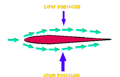
Wing creates lift by creating pressure difference between the upper and lower surfaces of the wing with low pressure above and high-pressure underneath.
One of the most important aspects that helps create lift is the viscosity of the medium as it creates vortices that produce lift conditions.
LIFT
In order for an aircraft to rise into the air, a force must be created that equals or exceeds the force of gravity. This force is called lift. In heavier-than-air craft, lift is created by the flow of air over an airfoil. The shape of an airfoil causes air to flow faster on top than on bottom. The fast-flowing air decreases the surrounding air pressure. Because the air pressure is greater below the airfoil than above, a resulting lift force is created.
The Bernoulli’s theorem is the main cause explaining lift(it has been explained later in the blog)
(source-https://web.mit.edu/16.00/www/aec/flight.html)

(source- https://web.mit.edu/16.00/www/aec/flight.html)
CL =>lift coefficient
0.5*rho*v^2=> dynamic pressure
S= surface area
Although along with lift, some drag is induced also called as induced drag (I will talk about this in this blog)
EQUAL TRANSIT THEORY:
It is a false theory explaining lift that states “because aerofoils are shaped with the upper surface longer than the bottom, air molecules that pass over the top of the aerofoil have further to travel than underneath.” The theory states that the air molecules have to reach the trailing edge at the same time, and in order to do that the molecules going over the top of the wing must travel faster than the molecules moving under the wing. Because the upper flow is faster, the pressure is lower, as known by Bernoulli's equation, and thus the difference in pressure across the aerofoil produces the lift.
BERNOULLIS THEOREM:
Given by Daniel Bernoulli, states that total mechanical energy of the flowing fluid (fluid pressure, the gravitational potential energy of elevation, and the kinetic energy of fluid motion) remains constant.

ASPECT RATIO
It is the ratio of the wingspan to the mean chord
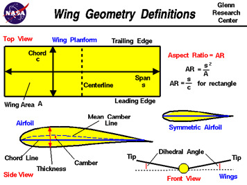
(source- https://www.grc.nasa.gov/www/k-12/airplane/geom.html)
For example, the aspect ratio of a Schleicher ASH 31 glider is 33.5 and that of a piper Cherokee is 5.6. Wings with higher aspect ratio produce a lot less induced drag due to lower wing tip area since lesser amounts of vortices. But as we go on increasing the wingspan, it causes bending of the wing as more mass moves away from the fuselage. To nullify this effect, we need to make the wing structurally stronger which means more material must be added which increases the induced drag. Planes with higher aspect ratio have longer wings which means they have a higher moment of inertia therefore they have lesser manoeuvrability for example when an ice skater pulls in their hands closer to their body to increase their angular speed. The F-14 can change its aspect ratio based on the need as we could see in ‘Top Gun: Maverick’.
The Boeing 787 dreamliner has a huge wingspan and the wings bend a lot, which in a regular aluminium based aircraft would be structurally dangerous but the 787 dreamliner is made out of a special carbon fibre- plastic composite that without increasing the weight by a lot provides a lot of structural support to the jet.
VORTICES:
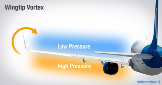
(SOURCE- https://www.boldmethod.com/learn-to-fly/aerodynamics/how-winglets-reduce-drag-and-how-wingtip-vortices-form/)
Wingtip vortices are circular patterns of rotating air left behind a wing as it generates lift. One wingtip vortex trails from the tip of each wing. Wingtip vortices are sometimes named trailing or lift-induced vortices because they also occur at points other than at the wing tips. This type of turbulence is significant because wing tip vortices decay quite slowly and can produce a significant rotational influence on an aircraft encountering them for several minutes after they have been generated. The origin of counter-rotating wing tip vortices is a direct and automatic consequence of the generation of lift by a wing. Lift is generated by the creation of a pressure differential over the wing surface. The lowest pressure occurs over the upper wing surface and the highest pressure under the wing. This pressure differential triggers the roll up of the airflow aft of the wing resulting in swirling air masses trailing downstream of the wing tips. The vortex strength increases proportionally to weight. The potential for hazardous wake vortex turbulence is greatest where aircraft follow the same tracks - i.e., are 'in trail' and closely spaced. This situation is mostly encountered close to the ground in the vicinity of airports where aircraft are on approach to or departure from runways at high frequencies. Sudden uncommanded roll moments.
GROUND EFFECT:
The positive influence on the lifting characteristics of the horizontal surfaces of an aircraft wing when it is close to the ground. This effect is a consequence of the distortion of the airflow below such surfaces attributable to the proximity of the ground. I know it sounds very complex but what it really means is that there is some “extra lift” generated by an aircraft as it approaches landing due to reduction of the induced drag. The increase in lift created by ground effect comes primarily from a reduction in the amount of induced drag generated which improves the lift/drag ratio. When generated in proximity to the ground, the form of the wing tip vortex, which is always generated when an aerofoil moves through the air, because pressure beneath a wing is always higher than that above it, is modified. Instead of being circular, vortices in proximity to the ground become elliptical as the airflow is pushed outwards. This causes the effective aspect ratio of the wing to become greater than the geometric aspect ratio and reduces induced drag. The direct effect on lift arises because a reduction in both upwash and downwash, as the air beneath a wing is compressed by ground proximity, creates a cushion effect.
ANGLE OF ATTACK:
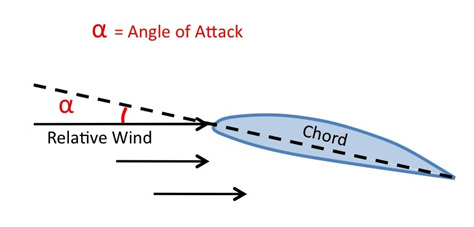
(SOURCE- https://skybrary.aero/articles/angle-attack-aoa)
The Angle of Attack is the angle at which relative wind meets an aerofoil. It is the angle formed by the Chord of the aerofoil and the direction of the relative wind. An increase in angle of attack results in an increase in both lift and induced drag, up to a point. Too high an angle of attack and the airflow across the upper surface of the aerofoil becomes detached, resulting in a loss of lift, otherwise known as a stall.
CENTRE OF PRESSURE:
As an object moves through a fluid, the velocity of the fluid varies around the surface of the object. The variation of velocity produces a variation of pressure on the surface of the object. Integrating the pressure times the surface area around the body determines the aerodynamic force on the object the average location of the pressure variation the centre of pressure in the same way that we call the average location of the weight of an object the centre of gravity. Determining centre of pressure of an aircraft is very important as it is used for stabilising the aircraft.
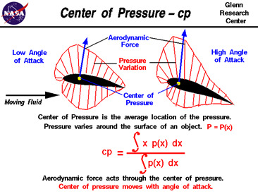
(SOURCE- https://www.grc.nasa.gov/www/k-12/airplane/cp.html)
FLAPS:
Flaps consist of a hinged panel or panels mounted on the trailing edge of the wing. When extended, they increase the camber and, in most cases, the chord and surface area of the wing resulting in an increase of both lift and drag and a reduction of the stall speed. These factors result in an improvement in take-off and landing performance
There are various types of flaps:
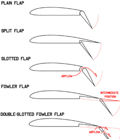
Wing flaps are a significant part of the take-off and landing process. When the airplane is taking off, the flaps help to produce more lift. Conversely, flaps allow for a steep but controllable angle during landing. During both, efficient use of flaps help to shorten the amount of runway length needed for take-off and landing. Wing flaps change the sape of the airplane wing. They divert the air around the wing as necessary. The settings of the flap determines whether they are used to increase lift (as on take-off) or increase drag (used on landing.) When the airplane’s flaps are up, the camber of the airplane is such that the wings can produce more lift. Depending on the aircraft, the flap settings are usually between five and fifteen degrees. After lift-off, the wing flaps are retracted completely so that they do not begin to produce drag.
Conversely, extending the flaps of the airplane creates a “broken wing,” which increases drag. This also lower’s the airplane’s stall speed. It helps the airplane to slow down.
THRUST:
It is the mechanical force that opposes drag and needs some sort of a propulsion system to push the aircraft forward. Thrust is generated most often through the reaction of accelerating a mass of gas. Since thrust is a force, it is a vector quantity having both a magnitude and a direction. The engine does work on the gas and accelerates the gas to the rear of the engine; the thrust is generated in the opposite direction from the accelerated gas. The magnitude of the thrust depends on the amount of gas that is accelerated and on the difference in velocity of the gas through the engine.
DRAG
Drag is a mechanical force. It is generated by the interaction and contact of a solid body with a fluid. For drag to be generated, the solid body must be in contact with the fluid. If there is no fluid, there is no drag. Drag is generated by the difference in velocity between the solid object and the fluid. There must be motion between the object and the fluid. The magnitude depends on the viscosity of the air and the relative magnitude of the viscous forces to the motion of the flow. There is an additional drag component caused by the generation of lift. Aerodynamicists have named this component the induced drag. It is also called "drag due to lift" because it only occurs on finite, lifting wings. Induced drag occurs because the distribution of lift is not uniform on a wing but varies from root to tip. For a lifting wing, there is a pressure difference between the upper and lower surfaces of the wing. Vortices are formed at the wing tips, which produce a swirling flow that is very strong near the wing tips and decreases toward the wing root. The local angle of attack of the wing is increased by the induced flow of the tip vortex, giving an additional, downstream-facing, component to the aerodynamic force acting on the wing. The force is called induced drag because it has been "induced" by the action of the tip vortices.
Also, I found this really cool video on drag: https://www.grc.nasa.gov/www/Wright/podcast/Podcast_Forces_Drag.m4v
BIBLIOGRAPHY:
https://www.youtube.com/watch?v=edLnZgF9mUg
https://ocw.mit.edu/courses/16-687-private-pilot-ground-school-january-iap-2019/video_galleries/class-videos/
https://www.boldmethod.com/learn-to-fly/aircraft-systems/how-does-aspect-ratio-affect-a-wing/
https://www.grc.nasa.gov/www/k-12/airplane/geom.html
https://www.grc.nasa.gov/www/k-12/airplane/airplane.html
https://www.grc.nasa.gov/www/k-12/airplane/forces.html
https://web.mit.edu/2.972/www/reports/airfoil/airfoil.html
https://web.mit.edu/16.00/www/aec/flight.html
https://owlcation.com/stem/Aerodynamics-The-Theory-of-Lift#:~:text=%22Equal%20Transit%22%20theory%2C%20also,further%20to%20travel%20than%20underneath.
https://skybrary.aero/articles/induced-drag#:~:text=Induced%20Drag%20is%20an%20inevitable,pressure%20outside%20the%20wing%20tip.
https://www.britannica.com/science/Bernoullis-theorem
https://www.grc.nasa.gov/www/k-12/airplane/geom.html
https://www.boldmethod.com/learn-to-fly/aircraft-systems/how-does-aspect-ratio-affect-a-wing/
https://skybrary.aero/articles/wake-vortex-turbulence
https://www.boldmethod.com/learn-to-fly/aerodynamics/how-winglets-reduce-drag-and-how-wingtip-vortices-form/
https://skybrary.aero/articles/ground-effect#:~:text=Ground%20effect%20is%20the%20name,the%20proximity%20of%20the%20ground.
https://skybrary.aero/articles/angle-attack-aoa
https://www.grc.nasa.gov/www/k-12/airplane/cp.html
https://calaero.edu/wing-flaps-function-and-purpose/
https://calaero.edu/wing-flaps-function-and-purpose/
https://www.grc.nasa.gov/www/k-12/airplane/thrust1.html
#engineering#engineer#physics#science#aerospace#tech#aerodynamics#planes#aviation#airplanes#aircraft#pilotstuff#flight#plane
7 notes
·
View notes
Text
The coolest commercial jet in the world??!!
INTRODUCTION
The days of the a380 and the humped 747 are gone and the 787 dreamliner is at the forefront of this revolution making it my favourite commercial airliner.
MATERIAL
About 50 percent of it is made of carbon fiber composite making it the first commercial jet in the world to be made up primarily of this material.
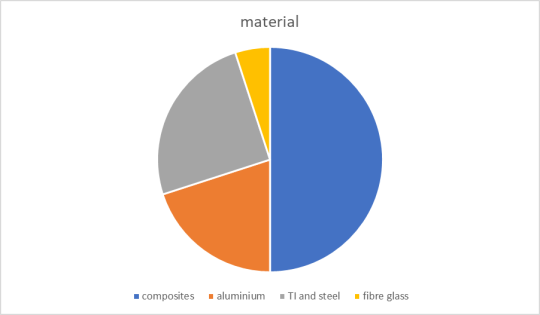
Composites are composed of 2 or more materials. Carbon reinforced plastics are composed of extremely strong carbon fibres bound together by plastic.
Carbon fibre is very strong and very light. It is 5 times stronger than steel and twice as stiff. Since they are very thin strands, thy can’t create solid structures, therefore, are bounded together by the plastic resin otherwise they would just form a strong but flexible fabric. Which is useful as it can be made into any shape required thus helping in forming the smooth curves of a jet.
Fun Fact- Boeing had to make customised ovens for the resin to heat in after it had been laid on the mould.
The 787 can also accommodate large windows on its fuselage as it is made up of composites. A hole this large on an aluminium jet would result in build up of stress around the window boundaries due to deviation of stress contours around the holes. Over a period of time, this would lead to damage on the body of the jet which will shorten the lifespan of the jet by a lot.
Aluminium based jets also pose another problem that has been solved by the use of carbon fibre composite. Use of joints and fasteners to rivet the pieces of aluminium together created small bumps and imperfections on the surface of the jet that created a lot of drag. Since the fuselage is now essentially a monolithic structure made of carbon composite, this drag is eliminated.
WINGS Wing Spar is the main structural component of a wing and its main job is to resist the upward bending force. In the 787 dreamliner, it is made up of carbon fibre composites and are structured by aluminium plates. This structure is hollow and acts as a space to store fuel in the jet. Carbon fibre composites have another quality that make them better for making wings. Carbon fibre composites can deform about 1.9% before entering the plastic region whereas aluminium can deform less than 1%.

(stress-strain graph depicting elastic and plastic regions. Source- https://www.smlease.com/entries/mechanical-design-basics/stress-strain-curve-diagram/)
Therefore, the wings can be super flexible. During the flight, the wingtips of a 787 dreamliner can move upward by about 3m.
The wings of a 787 are not the same as that of other aluminium jets. Due to its high flexibility, engineers designed the wings with a high aspect ratio. Aspect ratio is the ratio of the wing span to the mean chord of the wing. Gliders have high aspect ratio and the delta wings of a fighter jet have low aspect ratio. The 777 had an aspect ratio of 9 but the 787 has the aspect ratio of 11!
Thus even though composites are stiffer than aluminium, the wings of 787 bend more due to higher aspect ratio.
Higher aspect ratio means a larger wingspan as the vortex drags at the tip of wing, by spreading the area of wing over a longer wing, we minimize the pressure that drives vortices thus, the energy loss due to vortex drag is reduced. Another difference wings of the 787 dreamliner is the airfoil itself. The 787 uses a supercritical airfoil.
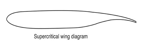
Tested in the early 1970s by NASA at the Dryden Flight Research Centre is now universally recognized by the aviation industry as a wing design that increases flying efficiency and helps lower fuel costs. Conventional wings are rounded on top and flat on the bottom. The SCW is flatter on the top, rounded on the bottom, and the upper trailing edge is accented with a downward curve to restore lift lost by flattening the upper surface.
THE PROBLEM WITH COMPOSITES
One of the things that stands out the most in the material composition of the 787 is the extensive use of titanium over aluminium since titanium is an expensive metal.
Aluminium on its own doesn’t corrode but when kept near carbon fibre, it oxidises rapidly. This is due to a phenomenon known as galvanic corrosion. When 2 materials with dissimilar electric potentials are kept in contact with each other with an electrolyte such as salt water, exchange of ions takes place.
Fun Fact- To reduce the cost of manufacturing Titanium, Boeing partnered with Norsk Titanium which 3-D print titanium parts thus eliminating the wastage of metal.
There is another issue with composites, even though carbon fibre is a good conductor of electricity, the plastic resin is an insulator and thus doesn’t allow electricity to conduct through it in case of lightning strikes. Thus, Boeing had to add strips of copper all around the fuselage to help it conduct lightning.
BIBLIOGRAPHY:
https://www.nasa.gov/pdf/89232main_TF-2004-13-DFRC.pdf
https://www.nasa.gov/centers/armstrong/news/FactSheets/FS-044-DFRC.html
https://www.smlease.com/entries/mechanical-design-basics/stress-strain-curve-diagram/
https://www.innovativecomposite.com/what-is-carbon-fiber/#:~:text=Carbon%20Fiber%20is%20a%20polymer,steel%20and%20twice%20as%20stiff.
https://www.sciencedirect.com/topics/engineering/boeing-787-dreamliner
https://www.aerospace-technology.com/projects/dreamliner/
https://www.boeing.com/commercial/787/by-design/#/advanced-composite-use
https://www.youtube.com/watch?v=lapFQl6RezA
#boeing#physics#science#aerospace#tech#aerodynamics#engineer#engineering#flights#airlines#pilotstuff#boeing 787#dreamliner#composites#wings
23 notes
·
View notes
Text
James Webb Space Telescope First Images
12th July 2022 marks one of the most important days in the history of mankind. James Webb Space Telescope revealed its first images and I am at a loss for words. This blog is more than a way to share information but is a thanks to all the scientists, engineers, ad everyone else on the Webb team and a way to congratulate the entire scientific community and human kind as this marks a major step in unravelling the universe. Now I know that mine is an aerospace page but this one is going to have an astrophysics and astronomy side to it. If you want to read about the engineering behind the JWST the do read-( https://www.tumblr.com/blog/view/aerospace-anant/672455873494384640?source=share)
SMACS 0723

NASA’s James Webb Space Telescope has delivered the deepest and sharpest infrared image of the distant universe so far. Webb’s First Deep Field is galaxy cluster SMACS 0723, and it is teeming with thousands of galaxies – including the faintest objects ever observed in the infrared. Webb’s image is approximately the size of a grain of sand held at arm’s length, a tiny sliver of the vast universe. The combined mass of this galaxy cluster acts as a gravitational lens, magnifying more distant galaxies, including some seen when the universe was less than a billion years old. Einstein’s general theory of relativity describes how mass concentrations distort the space around them.
A gravitational lens can occur when a huge amount of matter, like a cluster of galaxies, creates a gravitational field that distorts and magnifies the light from distant galaxies that are behind it but in the same line of sight. The effect is like looking through a giant magnifying glass. It allows researchers to study the details of early galaxies too far away to be seen with current technology and telescopes.
It is a composite made from images at different wavelengths, totalling 12.5 hours using the NIRcam – achieving depths at infrared wavelengths beyond the Hubble Space Telescope’s deepest fields, which took weeks.
This image shows the galaxy cluster SMACS 0723 as it appeared 4.6 billion years ago, with many more galaxies in front of and behind the cluster. We are looking back in time to within a billion years after the big bang when viewing the youngest galaxies in this field. The light was stretched by the expansion of the universe to infrared wavelengths that Webb was designed to observe. Other features include the prominent arcs in this field. The powerful gravitational field of a galaxy cluster can bend the light rays from more distant galaxies behind it, just as a magnifying glass bends and warps images.
2. WASP-96b
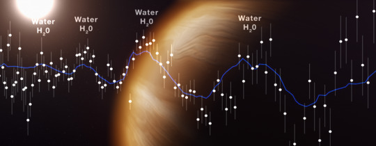
With a mass less than half that of Jupiter and a diameter 1.2 times greater, WASP-96 b is much puffier than any planet orbiting our Sun. And with a temperature greater than 1000°F, it is significantly hotter. WASP-96 b orbits extremely close to its Sun-like star, just one-ninth of the distance between Mercury and the Sun, completing one circuit every 3½ Earth-days. The combination of large size, short orbital period, puffy atmosphere, and lack of contaminating light from objects nearby in the sky makes WASP-96 b an ideal target for atmospheric observations. The observation, reveals the presence of specific gas molecules based on tiny decreases in the brightness of precise colours of light, is the most detailed of its kind to date, demonstrating Webb’s unprecedented ability to analyse atmospheres hundreds of light-years away. On June 21, Webb’s NIRISS measured light from the WASP-96 system for 6.4 hours as the planet moved across the star. The result is a light curve showing the overall dimming of starlight during the transit, and a transmission spectrum revealing the brightness change of individual wavelengths of infrared light between 0.6 and 2.8 microns.
While the light curve confirms properties of the planet that had already been determined from other observations – the existence, size, and orbit of the planet – the transmission spectrum reveals previously hidden details of the atmosphere: the unambiguous signature of water, indications of haze, and evidence of clouds that were thought not to exist based on prior observations.
3. STEPHENS QUINTET

Stephan’s Quintet, a visual grouping of five galaxies. This enormous mosaic is Webb’s largest image to date, covering about one-fifth of the Moon’s diameter. It contains over 150 million pixels and is constructed from almost 1,000 separate image files. With its powerful, infrared vision and extremely high spatial resolution, Webb shows never-before-seen details in this galaxy group. Sparkling clusters of millions of young stars and starburst regions of fresh star birth grace the image. Sweeping tails of gas, dust and stars are being pulled from several of the galaxies due to gravitational interactions. Most dramatically, Webb captures huge shock waves as one of the galaxies, NGC 7318B, smashes through the cluster. Tight groups like this may have been more common in the early universe when their superheated, infalling material may have fuelled very energetic black holes called quasars. Even today, the topmost galaxy in the group – NGC 7319 – harbours an active galactic universe, a supermassive black hole 24 million times the mass of the Sun. It is actively pulling in material and puts out light energy equivalent to 40 billion Suns. In NGC 7320, the leftmost and closest galaxy in the visual grouping, Webb was able to resolve individual stars and even the galaxy’s bright core. it will help scientists understand the rate at which supermassive black holes feed and grow. Webb also sees star-forming regions much more directly, and it is able to examine emission from the dust – a level of detail impossible to obtain until now.
4. SOUTHERN RING NEBULA
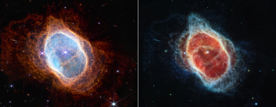
Two cameras aboard Webb captured the latest image of this planetary nebula, catalogued as NGC 3132, and known informally as the Southern Ring Nebula. It is approximately 2,500 light-years away. The dimmer star at the centre of this scene has been sending out rings of gas and dust for thousands of years in all directions, and NASA’s James Webb Space Telescope has revealed for the first time that this star is cloaked in dust. This observation shows the Southern Ring Nebula almost face-on, but if we could rotate it to view it edge-on, its three-dimensional shape would more clearly look like two bowls placed together at the bottom, opening away from one another with a large hole at the center.
Two stars, which are locked in a tight orbit, shape the local landscape. Webb's infrared images feature new details in this complex system. The stars – and their layers of light – are prominent in the image from Webb’s NIRCam on the left, while the image from Webb’s MIRI on the right shows for the first time that the second star is surrounded by dust. The brighter star is in an earlier stage of its stellar evolution and will probably eject its own planetary nebula in the future.
In the meantime, the brighter star influences the nebula’s appearance. As the pair continues to orbit one another, they “stir the pot” of gas and dust, causing asymmetrical patterns.
Each shell represents an episode where the fainter star lost some of its mass. The widest shells of gas toward the outer areas of the image were ejected earlier. Those closest to the star are the most recent. Tracing these ejections allows researchers to look into the history of the system.
As the star ejects shells of material, dust and molecules form within them – changing the landscape even as the star continues to expel material. This dust will eventually enrich the areas around it, expanding into what’s known as the interstellar medium. And since it’s very long-lived, the dust may end up traveling through space for billions of years and become incorporated into a new star or planet.
5. CARINA NEBULA

This landscape of “mountains” and “valleys” speckled with glittering stars is actually the edge of a nearby, young, star-forming region called NGC 3324 in the Carina Nebula. Captured in infrared light by NASA’s new James Webb Space Telescope, this image reveals for the first time previously invisible areas of star birth. Called the Cosmic Cliffs, Webb’s seemingly three-dimensional picture looks like craggy mountains on a moonlit evening. In reality, it is the edge of the giant, gaseous cavity within NGC 3324, and the tallest “peaks” in this image are about 7 light-years high. The cavernous area has been carved from the nebula by the intense ultraviolet radiation and stellar winds from extremely massive, hot, young stars located in the center of the bubble, above the area shown in this image.
The blistering, ultraviolet radiation from the young stars is sculpting the nebula’s wall by slowly eroding it away. Dramatic pillars tower above the glowing wall of gas, resisting this radiation. The “steam” that appears to rise from the celestial “mountains” is actually hot, ionized gas and hot dust streaming away from the nebula due to the relentless radiation. Because of Webb’s sensitivity to infrared light, it can peer through cosmic dust to see these objects. Protostellar jets, which emerge clearly in this image, shoot out from some of these young stars. The youngest sources appear as red dots in the dark, dusty region of the cloud. Objects in the earliest, rapid phases of star formation are difficult to capture, but Webb’s extreme sensitivity, spatial resolution, and imaging capability can chronicle these elusive events.
These observations of NGC 3324 will shed light on the process of star formation. Star birth propagates over time, triggered by the expansion of the eroding cavity. As the bright, ionized rim moves into the nebula, it slowly pushes into the gas and dust. If the rim encounters any unstable material, the increased pressure will trigger the material to collapse and form new stars.
BIBLIOGRAPHY:
1. https://www.nasa.gov/webbfirstimages
2. https://webbtelescope.org/contents/news-releases/2022/news-2022-031
3. https://webbtelescope.org/glossary.html#h3-CK-2572b869-1584-45c0-a18b-0c5ffcf32e57
4. https://esawebb.org/announcements/ann2207/
5. https://hubblesite.org/contents/articles/gravitational-lensing
#james webb first full colour image#physics#science#aerospace#space#tech#james webb space telescope#james webb 5 points on what new telescope aims to achieve james webb#james webb deepest sharpest view of universe#nasa#carina nebula#astronomy#webb#jwst#images#first images
13 notes
·
View notes
Text
Aerodynamics of F1
INTRODUCTION
It has now been more than 70 years since F1 first started and with growth in engine technology, the rules on the power units f an F1 car have become quite strict giving aerodynamics engineers a lot to play around to improve the performance of the car. Today we’ll be looking at the aerodynamics in an F1 car. Topics that I’ll be covering today:
1. Downforce and the ground effect
2. Front wing
3. Rear Wing
4. DRS
5. Diffuser
DOWNFORCE
Lift is generated in an aircraft by accelerating the air above the wings and thus creating a low pressure area above the wing and creating an area of slow moving air below the wing creating a high pressure area. This imbalance in pressure creates lift. A F1 car works on the exact opposite principle and is essentially an inverted wing. A F1 car tries to create a low pressure region below the car and a high pressure region above the car to increase the downforce. Now, you must be wondering that why is downforce given so much importance rather than reducing the drag force? Increasing the downforce improves the stability of the car and keeps it closer to the ground thus increasing its speed and traction around corners.
Fdown = 0.5DClAV²
Where, D= density of air
Cl=Coefficient of lift
A=frontal area
V= velocity of object
So, a F1 car at 100mph will produce roughly 750kg of downforce. Interestingly, lower weight limit of a F1 car is 743kg so you could in theory drive the car upside down.
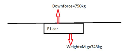
Ground effect – where the pressure of air under the car is lower than the pressure above the car, creating a sucking effect that pushes the car to the ground.
FRONT WING
(IMAGE SOURCE- https://www.totalsimulation.co.uk/secrets-formula-1-part-3-role-front-wing/)
The front wing is a very important aerodynamic device in a F1 car. It has 2 main purposes, first to generate downforce and second to manipulate the flow to the rest of the car by controlling the vortices over and under the vehicle.
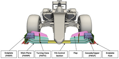
Endplates are one of the most important aspects of the front wing. They control the flow of air around the Formula One car by redirecting the airflow around the tires. This minimizes the overall drag resistance produced and facilitates the airflow to continue back to the side pods and the car floor. In addition, the tips of the front wings coincide with the ends of the tires. This creates unnecessary turbulence in front of the wheels and increases drag. Hence, the inside edges of the end plates are curved to ensure that the air flows around the tires.

(IMAGE SOURCE- https://www.simscale.com/)
F1 front wings are sharply pointed and fine edged, to promote the creation of turbulent vortices, which the cascade elements direct underneath the floor of the car. Designers want to create vortices that they can control, but without endplates, both on the front wing and rear wing, uncontrollable vortices are produced, which add to the drag coefficient of the car but don’t increase downforce production, so are undesired. The fast moving vortices now travelling underneath the car are of higher speed and lower pressure than the air going over the car, thus increasing the downforce-ground effect.
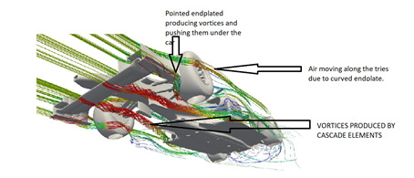
(IMAGE SOURCE- https://www.totalsimulation.co.uk/secrets-formula-1-part-3-role-front-wing/, LABELS- self)
REAR WING
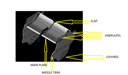
(f1 rear wing. Source- https://www.presticebdt.com/. Labels-self)
The rear wing is among the most regulated aerodynamic device of a Formula One car. Teams will have track specific rear wings depending on how much downforce is required on a particular track. The FIA allows a span of 101cm for the rear wing and an additional 5cm for each of the endplates. The end of the rear wings is designed and finished within these 5 cm on either side. The rear wing has to be 35cm in front of the rear tip of the car and have to be 22 or less cm deep.
The rear wing of a F1 has the aim to generate downforce to counterbalance the downforce produced by the front assembly. In fact, the force distribution alongside the vehicle determines the overall balance of a car. The rear wing of a F1 generates about ~10% less downforce than the front wing. The rear wing works quite differently than the front wing as it can’t exploit ground effect and work with disturbed flow.
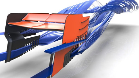
(Airflow over the rear wing. Source- https://www.presticebdt.com/the-aerodynamics-of-f1-rear-wing-cfd-explained/)
1. A main plane: the thicker profile of the rear wing assembly. This part remains fixed when DRS is open.
2. the smaller profile which acts as a slotted flap increasing downforce and preventing flow detachment. This part is moved and opened by the DRS system.
3. Middle trim: this part of the endplate, is sometimes trimmed in order to better drive the flow coming from the wheels and the bodywork.
4. Bottom trim/louvers: These louvers located in the lower part of the endplates are designed to work efficiently with the rear diffuser and exhaust gas.
DRS
DRS stands for drag reduction system, it was introduced in f1 in 2011 in order to improve overtaking. It is a device that allows the reduction of the downforce acting on the vehicle with less adherence to the track and therefore an increase in speed, but also with a decrease in stability.
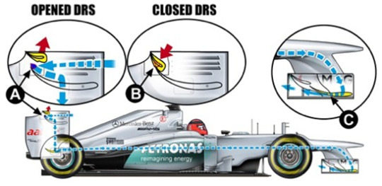
(Image source- https://www.presticebdt.com/)
The addition of the flap has the aim to increase the overall camber of the main wing, leading to an increased downforce and preventing flow separation.
When the airflow approaches the rear wing with DRS in closed position a large high pression area is generated on the upper side of the wing-flap profile, while a suction area is present underneath the profile. A qualitative effect of DRS effect on F1 aerodynamics is reported on the following image. The red colors identify a high pressure region while the blue one a low pressure area.
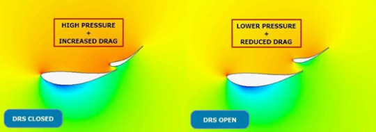
(pressure difference when DRS is opened or closed. Source- https://www.presticebdt.com/)
When the DRS system is activated, the high pressure on the upper profiles greatly declines. The reduced pressure means a reduced downforce and drag. By enabling the DRS system, a F1 car can have over 10 km/h gain. However, the overall impact of DRS on car performance are greatly influenced by the profile chosen as main wing. For instance, when low angle of attacks and low downforce profiles are used , also the effectiveness of the DRS system is reduced.
DIFFUSER
The diffuser is an area of bodywork at the rear of the car and the air flowing below the car, exits through the diffuser on the rear of the car. Although wings and diffusers work similarly, they are based on different concepts. A diffuser serves to eject air out from the underside of the car. This pulling action increases the velocity of the air below the car, so that the more slowly moving air above the car will push the car into the ground. The suction effect is a result of Bernoulli's equation, which states that where speed of the fluid is higher, pressure must be lower. Therefore the pressure below the race car must be lower than the pressure at the outlet since the speed of the air below the race car will be higher than the speed of the air at the outlet.
The diffuser in itself doesn't produce a reduction in pressure. The role of the diffuser is to expand the flow from underneath the car to the rear, decrease the flow's velocity from inlet of the diffuser to outlet (so that at the outlet the flow velocity is similar to the free stream velocity), in turn produce a pressure potential, which will accelerate the flow underneath the car resulting in reduced pressure and as such, a desired increased downforce generation.
(Source- https://www.racecar-engineering.com/)
The addition of the vertical ‘fences’ to a diffuser help to optimize the diffusers efficiency by ensuring that the air is only drawn only from the underbody and does not spill in from the upper body surfaces.

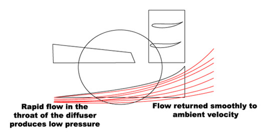
(Pressure on the underside of a diffuser. Source-- https://www.racecar-engineering.com/)
shows the pressure coefficient of a generic diffuser design, with blue representing lowest pressure areas and red highest pressure. This clearly illustrates the reduction in pressure at the throat area as the velocity increases and the subsequent reduction in pressure for the underfloor as the diffuser sucks the car to the ground.
BIBLIOGRAPHY
1. https://thegsaljournal.com/2020/06/28/aerodynamics-in-formula-1/
2. https://f1chronicle.com/how-does-a-formula-1-car-work/
3. https://www.bbc.com/sport/formula1/47527705#:~:text=To%20put%20this%20into%20perspective,as%20much%20downforce%20as%20possible.
4. http://www.formula1-dictionary.net/downforce.html
5. https://www.totalsimulation.co.uk/secrets-formula-1-part-3-role-front-wing/
6. https://www.presticebdt.com/the-aerodynamics-of-f1-rear-wing-cfd-explained/#:~:text=The%20rear%20wing%20of%20a%20F1%20generates%20about%20~10%25%20less,wheels%20interaction%20with%20the%20flow.
7. https://www.presticebdt.com/how-f1-drs-works-the-aerodynamics-of-formula-one-drs-explained/
8. https://www.f1technical.net/articles/9
9. www.formula1-dictionary.net
10. https://www.racecar-engineering.com/tech-explained/diffusers-engineering-basics-aerodynamics/
#aerospace#aerodynamics#car#f1#formula1#formula one#wing#DRS#engineer#engineering#mechanicaldesign#physics#science#racing#motorsport#race#ferrari#max verstappen#mercedes amg f1#red bull f1#karting
967 notes
·
View notes
Text
ISRO-The Indian Space Agency
ISRO stands for Indian Space Research Organization, it is the national space agency of India and was established in 1969 by Vikram Sarabhai in Bengaluru. The chairman of ISRO is Shri S. Somnath who succeeded Dr. K Sivan in 2022.
LAUNCH VEHICLES
1)Satellite Launch Vehicle(SLV-3)
· First launch vehicle made by India, it had its first successful launch in 1980 and made India the 6th country in the world with orbital launch capabilities.
2) Augmented Satellite Launch Vehicle(ASLV)
· Another small satellite launch vehicle launched in 1980s to put the satellite into geostationary orbit. It was dropped due to insufficient funds and multiple failures.
3) Polar Satellite Launch Vehicle(PSLV)
· First Indian medium lift launch vehicle that has enabled India to put all its remote sensing satellites into sun synchronous orbit. It is India’s primary launch vehicle with more than 50 launches.
4) Geosynchronous Satellite Launch Vehicle (GSLV)
· Envisioned in 1990s to deliver heavier payloads into orbit. India had to make its own cryogenic engine (CE-7.5).
5) GSLV Mark III(LVM3)
· ISRO’s heaviest rocket and helps India deliver all its communication satellites. It is also expected to carry out India’s first manned mission the Gaganyaan.
MANGALYAAN
The Mangalyaan is India’s approach to the red planet. It was India’s first interplanetary mission and was launched on 5thNovember 2013 and has been orbiting Mars since September 2014. It made ISRO the 4th space agency to achieve Mars orbit, it made India the first Asian country to reach Martian Orbit and the first country in the world to achieve so in its maiden attempt. Another amazing fact about the Mangalyaan mission is that it just cost $75 million which is a third of the budget of the movie ‘Martian’. ISRO plans to launch another mission to mars the Mangalyaan-2 by 2025 and possibly touch the Martian surface.
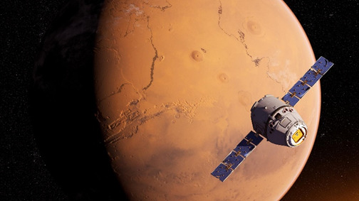
(The Mangalyaan orbiting Mars. By- https://amuedge.com/edl-challenges-with-indias-mangalyaan-2-mission-part-i/)
CHANDARYAAN
The Chandaryaan missions are India’s trips to the moon. Chandaryaan-1 was launched way back in 2008 and made India the 4th country in the world to have its flag on the moon. It was intended to work for 2 years but due to technical issues, it had to be retired after 312 days but, it achieved most of its objectives such as testing the soil for water traces. Chandaryaan 2 is ISRO’s latest lunar mission that targeted the south pole of the moon in an attempt to find frozen water and was supposed to be the 4th country to soft land at the south pole of the lunar surface but the Vikram lander crashed into the Lunar surface due to a last-minute glitch in the soft landing guidance software led to the failure of the lander's soft landing attempt after a successful orbital insertion. The Chandaryaan 3 will be India’s 3rdlunar mission and will attempt to soft land on the south pole of the moon but unlike the Chandaryaan-2, it not have an orbiter.
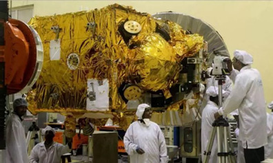
(Chandaryaan 2. Source- https://www.planetary.org/space-images/indias-mars-orbiter-mission-hardware)
GAGANYAAN
It will be India’s attempt to put a person in space. There have been a few Indians in space such as Rakesh Sharma and Kalpana Chawla but none of them flew as an Indian astronaut. Rakesh Sharma was a cosmonaut and Kalpana Chawla was an American astronaut. The mission has been designed for 3 people but the upgraded version will have rendezvous and docking capabilities. Prior to the actual launch of the astronauts, there will be 2 test unmanned flights the first one being in June 2022. The final manned mission is expected to be sometime in 2023. The Vikas engine will be used for the mission which is the core stage of the GSLV mk3. Vyommitra a robot will be on the unmanned missions to see the effect microgravity will have on human bodies, unlike other space agencies that use animals for the same
BIBLOGRAPHY:
1. https://www.isro.gov.in/
2. https://amuedge.com/edl-challenges-with-indias-mangalyaan-2-mission-part-i/
3. https://www.planetary.org/space-images/indias-mars-orbiter-mission-hardware
41 notes
·
View notes
Text
An update on the James Webb Space Telescope
As of 19thJanuary 2022, its been 25 days since the launch of the James Webb Space telescope and about 15 days since my last blog(https://aerospace-anant.tumblr.com/post/672455873494384640/james-webb-space-telescope-a-high-schoolers) , so I think it’s time for an update. The JWST is in it’s large stage and is expected to be put in the L2 orbit in another 5 days. Currently, the individual primary segments and the secondary mirror are moving up 12.5mm from their original stowed position to a deployed state where they are ready for the mirror alignment process. This process is very slow and takes place over a period of 10 days. To read more about this process-(https://blogs.nasa.gov/webb/2022/01/13/mirror-mirroron-its-way/ by Dr. Marshall Perrin).
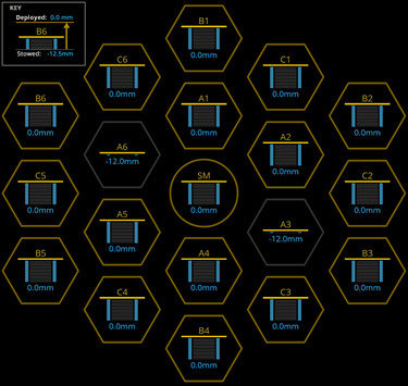
(Progress as of 23:53 IST on 18th January 2022, courtesy-https://www.jwst.nasa.gov/content/webbLaunch/whereIsWebb.html)
BIBLIOGRAPHY:
1) https://www.jwst.nasa.gov/content/webbLaunch/whereIsWebb.html
2) https://youtu.be/34U_RBOzHMA
#jwst#tech#physics#science#jwst launch date and time#james webb#technology#james webb space telescope
74 notes
·
View notes
Text
James Webb Space Telescope-A High Schooler's Approach
The James Web Space Telescope is a joint operation between NASA, European Space Agency and Canadian Space Agency and is the most powerful telescope ever! The secret behind it being the most powerful telescope is that it’s huge. It is 21 feet wide and it is impossible to transport something so large in space so, it is made up of 18 smaller hexagonal mirrors which need to work together as a monolith. There are 6 actuators behind each hexagon which help fine tune the telescope’s view. The telescope is an Infrared telescope to see far into the universe as the light from the furthest regions in space fall in the IR region due to red shift. But due to this, it has to be shielded from all the sun. So, the JWST will rest at Lagrange 2, at this point, the sun, Earth and the Moon are on the same side here, the JWST will open up a shield that will protect it. There are three mirrors which makes this telescope a three mirror anastigmatic telescope which means that the light is reflected three times that is three mirrors are present. Although another 4th mirror is also present but that is just for minor adjustment.
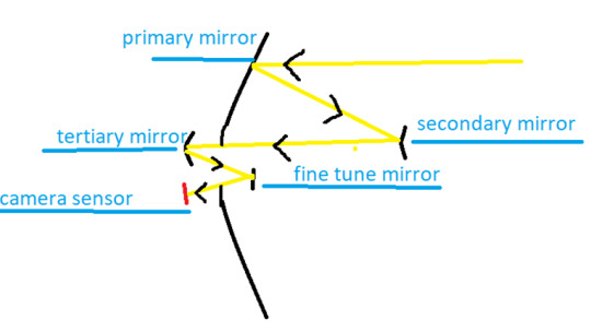
(A representation of a three mirror anastigmatic telescope)
The primary mirror acts as a large bowl and a concave mirror which concentrates all the light rays that it receives at its focus where the secondary mirror is present and this goes on till the light ray reaches the camera sensor.
The sun shield is something of an engineering marvel itself, it’s made up of 5 layers made of Kapton which is a thin plastic coated with metal. The thickness of each layer is a quarter of the thinnest human hair ever. This makes a temperature as low as 40K on the darker side. This low temperature poses another problem, the material of the hexagons must be able to survive such low temperatures so, Beryllium is being used. Much better detectors were required for the JWST so the combination of mercury cadmium telluride and arsenic doped silicon is used to make the detectors that can give the sensitivity to study the desired range of wavelengths. The telescope has an aperture of 6.6m and is designed to work in the IR range from 0.6 to27 μm wavelengths with the goal of extend to 29μm. 0.6μm lies in the visible range and can be observed by us but wavelengths of 27μm lies in the IR range. It is necessary for this telescope to be an IR telescope as if a light that started as a UV would have increased its wavelength to the IR spectrum due to red shifting, which is a result of the expansion of universe. Till now, we have observed light waves that had been red shifted by a factor of 11. This means that if a particle started with a wavelength of 0.1μ, had a wavelength of 1.2μ when we recorded it and in the JWST, sensors which can measure red shifting by a factor of 20 or 30 are present. On the warmer side of the telescope, all the systems and components used to run the observatory are present. Over here, we have the reaction wheels, rocket jets and fuel. Rocket jets are used to maintain the orbit as it is an unstable orbit. Reaction wheels are used to tip the telescope in the correct direction as they collect angular momentum and pushes on the telescope which isn’t totally balanced. The solar pressure is very small(a thousandth of a gram on a square meter of the observatory) but, in 0 g, even the smallest force can offset everything. The fuel required for rocket jets and deployment of reaction wheels determines the life of the telescope. After almost 25 years in making and a cost of $10 billion, the James Webb Space Telescope launched on 25th December 2021 and will hopefully help us clear many questions that we face today and raises a lot more.
BIBLIOGRAPHY:
How Does The James Webb Space Telescope Work?- https://youtu.be/4P8fKd0IVOs
Space.com- https://www.space.com/nasa-james-webb-space-telescope-mirror-explained
NASA Website- https://jwst.nasa.gov/content/webbLaunch/deploymentExplorer.html
#science#technology#physics#james webb space telescope#space#research#tech#aerospace#astronomy#astrophysics#cosmos
128 notes
·
View notes