#arduino
Text
My final project for my art and technology class! We were told to imagine that disaster struck the world, and we were forced to live in a bunker for 12 years, but after that we were able to live in the earth again. We had to make a museum as a class, and show what happened during the time in the bunker.
I created 12 flowers to show the 12 years, and they start out looking very flower like, and turn into mutated monsters.


This is the sunflower, the most flowery of all of the flowers. I used neopixel strips to light up the center of it, to show to hope in the beginning.


the next two are the hydrangea made out of bottle caps, and the lavender made out steel and rubber wire. These still look like flowers, and are modeled after actual flowers.
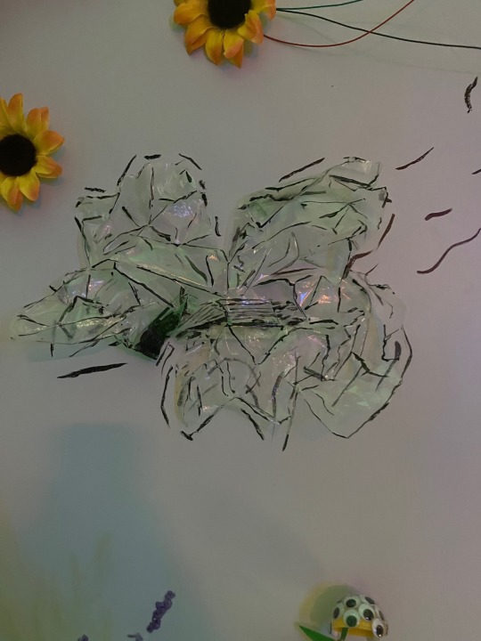
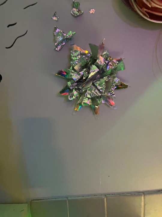
The first one is made out of plastic bags, the second is made out of tinfoil and cut up cds. These two are not modeled after actual flowers, and I focused more on the material than looking like a flower.

This is the rose, it is made out paper cups painted with water color, and covers the arduino. (that’s why it has wires coming out of it). This is my favorite flower, and I’m really happy with how well it turned out.

This is the clock. It has bits of most of the other flowers on it, and all the flowers have a trail flowing into/out of it. It represents the flow, and stoping of time that happens when you are trapped in a single place for a long time.
Now we are moving on to the weird ones!
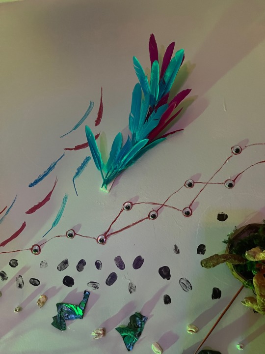
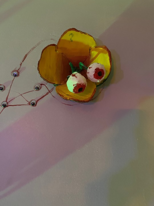
One made of feathers (I was running out of ideas and time) and one with eyeballs!
Second post will have the final flowers, and picture of everything! (i hit the picture limit for this post)
#art#arduino#flowers#sculpture#art and technology#you spend 12 years in a bunker and go crazy and make weird ass flowers
2 notes
·
View notes
Text
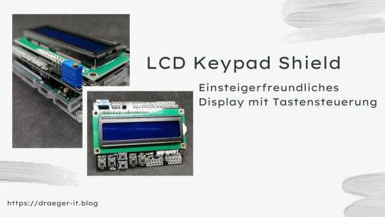
LCD Keypad Shield für Arduino: Einsteigerfreundliches Display mit Tastensteuerung
Das coole LCD Keypad Shield gibt es schon sehr lange auf dem Markt und wurde auch auf anderen Seiten schon beschrieben. Dieser Beitrag soll jedoch etwas tiefer gehen und ich möchte dir, nachdem ich den Aufbau und die Programmierung erläutert habe, ein cooles nützliches Projekt mit diesem zeigen.
https://youtu.be/4eqaoDKCIZU
Ich möchte meinem ehemaligen Abteilungsleiter im Elektroniklabor herzlich danken. Durch die großzügige Möglichkeit, sich bei der Auflösung des Labors zu bedienen, konnte ich unter anderem das LCD Keypad Shield für Arduino erhalten.

Technische Daten
Zunächst zu den technischen Daten des LCD Keypad Shield:
HerstellerDF-RobotBetriebsspannung5VAbmessungen80 mm x 58 mmFeatures2x16 Zeilen LCD-Display,
1x Potentiometer zur Regulierung der Hintergrundbeleuchtung,
6 Taster (davon 1 Taster für RESET),
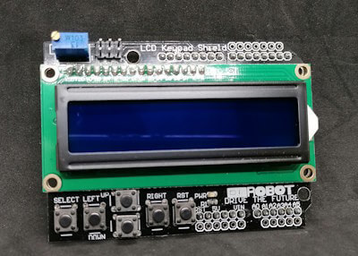
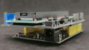
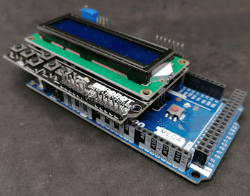
Aufbau des LCD Keypad Shield
Das Shield verfügt über ein 2x16 Zeichen LCD-Display und sechs Tasten, welche mit SELECT, LEFT, UP, DOWN, RIGHT und RST (Reset) beschriftet sind. Zusätzlich hast du ein Drehpotentiometer zum Regulieren der Hintergrundbeleuchtung.

Aufbau des LCD Keypad Shield von DF Robot
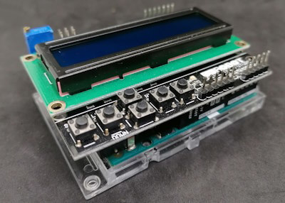
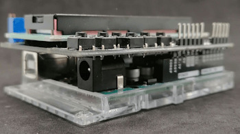
Das Shield ist fertig aufgebaut auf einer Platine, welche du direkt auf einen Arduino UNO R3 / R4, Leonardo oder Mega 2560 R3 stecken kannst. Du kannst mit zusätzlichen Stiftleisten noch die freien Pins des Mikrocontrollers nach oben führen und so an diese Pins weitere Komponenten (Sensoren, Aktoren) anschließen.
Der Mega 2560 R3 hat deutlich mehr digitale & analoge Pins und somit verbleiben noch weitere für ein eventuelles Projekt mit dem LCD Keypad Shield.
Pinout des LCD Keypad Shield
Bevor wir dieses Shield programmieren können, müssen wir zunächst prüfen, an welche Pins die Taster und das LCD-Display angeschlossen ist.
KomponenteArduino UNO R3LCD-DisplayRSD8EnableD9D4D4D5D5D6D6D7D7TasterA0
Analoge Werte der Tasten am LCD Keypad Shield
Die Taster sind alle am analogen Pin A0 angeschlossen und liefern beim Betätigen jeweils unterschiedliche Werte. Über diese Werte kann man die betätigte Taste im Code quasi recht einfach erkennen.
Tasteranaloger WertSELECT640LEFT409RIGHT0UP99DOWN256
Unterschiede bei Mikrocontrollern
Für die Schaltung in diesem Beitrag verwende ich den originalen Arduino UNO R3, dieser ist deutlich wertiger aufgebaut als die einfachen China Klone. Durch die andere Verarbeitung sind auch die Werte, welche die Tasten beim Betätigen liefern etwas anders als wie bei besagten Mikrocontrollern auch China.
Getestet habe ich die Werte mit:
- dem originalem Arduino UNO R3,
- dem Funduino UNO R3,
- einem Noname China Klone,
- dem Funduino Mega 2560 R3,
Programmieren des LCD Keypad Shield in der Arduino IDE
Die Programmierung erfolgt in der Arduino IDE wobei ich hier die aktuelle Version 2.0.x verwende. Du kannst die nachfolgenden Programme aber auch in der klassischen Version 1.8.x programmieren (welche unter Umständen etwas schneller ist).
Schritt 1 - auslesen der Taster
Mit nachfolgendem Code lesen wir zunächst die Werte der Tasten aus und geben diese auf der seriellen Schnittstelle aus.
#define taster A0
void setup() {
Serial.begin(9600);
pinMode(taster, INPUT);
}
void loop() {
Serial.println(analogRead(taster));
delay(250);
}
Das Shield habe ich hier an einen Funduino Mega 2560 angeschlossen und dieser liefert ein paar unterschiedliche Werte für die Tasten (um genau zu sagen, um eins versetzt).
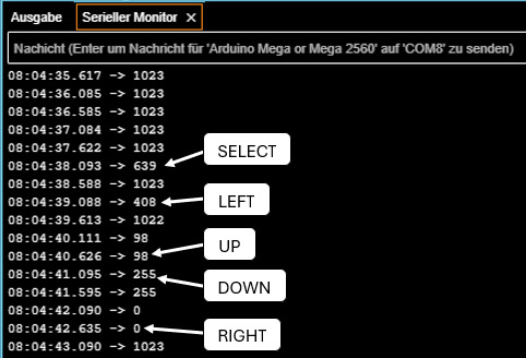
analoge Werte der Tasten am LCD Keyad Shield
Schritt 2 - Programmieren des 2x16 LCD-Display
Wie du ein LCD-Display programmierst, habe ich dir bereits im Beitrag Arduino Lektion 7: LCD Display ansteuern erläutert, hier greife ich zunächst das Beispiel auf und zeige den Text "Hallo Welt!" auf der ersten Zeile und auf der zweiten Zeile die Buchstaben A bis P.
#include
//Das Display ist wiefolgt mit dem Shield / Mikrocontroller verbunden
/**
* rs > D8
* enabled > D9
* D4 > D4
* D5 > D5
* D6 > D6
* D7 > D7
**/
LiquidCrystal lcd(8, 9, 4, 5, 6, 7);
void setup() {
//Das LCD-Display mit 16 Zeichen und 2 Zeilen initialisieren
//Die Bibliothek LiquidCrystal kann für viele LCD-Displays verwendet werden!
lcd.begin(16, 2);
//Erste Zeile mit dem Text "Hallo Welt!" belegen.
lcd.print("Hallo Welt!");
//Die zweite Zeile soll mit den Buchstaben A bis P belegt werden.
//Dafür legen wir uns eine Variable zeichen an und weisen dieser den Wert
//65 zu dieser repräsentiert den ASCII Wert A siehe (https://draeger-it.blog/ascii-tabelle/)
int zeichen = 65;
for (int i = 0; i < 16; i++) {
//Cursor an die Position i (aus der Schleife) und Zeile 1 setzen
//die erste Zeile hat den Wert 0 und die zweite 1
lcd.setCursor(i, 1);
//die Zahl in ein Charakter umwandeln
lcd.print(char(zeichen));
//Die Zahl um eins erhöhen.
zeichen++;
//eine kleine Pause von 350ms
delay(350);
}
}
void loop() {
//bleibt leer
}
Der obige Quellcode erzeugt die Ausgabe von "Hallo Welt!" in der ersten Zeile und die Buchstabenfolge von A bis P in der zweiten Zeile.
Beispiele für das LCD Keypad Shield am Arduino UNO R3
Nachdem ich dir jetzt gezeigt habe wie dieses Shield programmiert wird, möchte ich dir nun ein paar Beispiele aufzeigen welche du damit nachprogrammieren kannst.
Beispiel 1- navigieren durch ein Array
Mit den Navigationstasten kannst du recht einfach über ein Array navigieren und mit der Taste SELECT die Auswahl bestätigen.
Im ersten Beispiel möchte ich dir gerne zeigen wie du durch die Werte eines Arrays navigieren kannst.
#include
//initialisieren des Displays
LiquidCrystal lcd(8, 9, 4, 5, 6, 7);
//die Taster sind gemeinsam über den
//analogen Pin A0 angeschlossen
#define taster A0
//analoge Werte der Taster
const int SELECT = 640;
const int LEFT = 409;
const int RIGHT = 0;
const int UP = 99;
const int DOWN = 256;
//Aufbau des Menüs
//maximale Anzahl der Einträge im Array
const int NUM_MENU_ITEMS = 4;
//aktueller Index
int index = -1;
//das Menü
String menu = {
"Eintrag 1", "Eintrag 2", "Eintrag 3", "Eintrag 4"
};
//Feld für den Wert des Tasters welcher betätigt wurde.
int tasterValue = -1;
void setup() {
//das LCD-Display hat 2 Zeilen mit maximal 16 Zeichen pro Zeile
lcd.begin(16, 2);
//der Index ist initial auf -1 gesetzt,
//die Funktion displayMenuItem prüft anhand des Indexes und der gegebenen
//Richtung welche Einträge angezeigt werden sollen
displayMenuItem(true);
}
void loop() {
//auslesen des analogen Wertes, dieser ändert sich je nach Taster
tasterValue = analogRead(taster);
//prüfen welcher Taster betätigt wurde
switch (tasterValue) {
case UP:
displayMenuItem(false);
break;
case DOWN:
displayMenuItem(true);
break;
case SELECT:
doSomething();
break;
}
}
//Diese Funktion zeigt zwei Daten auf dem LCD-Display an, abhängig
//von dem Index und der Richtung welche navigiert werden soll.
void displayMenuItem(bool directionDown) {
//leeren des Displays
lcd.clear();
//Zeile 2 soll den Inhalt "-ENDE-" haben wenn das Ende des Menüs erreicht wurde.
String line2 = "-ENDE-";
//Wenn der Wert des Parameters
//directionDown Wahr/True ist UND
//der Wert vom index kleiner als die maximale Anzahl der Menüeinträge -1 ist, dann...
if (directionDown && index < NUM_MENU_ITEMS - 1) {
index++;
} else if (!directionDown && index > 0) {
index--;
}
//Die erste Zeile enthält den Text aus dem Menü mit dem Wert index.
//Der erste Eintrag im Array hat den Eintrag 0!
String line1 = menu;
//prüfen ob das Ende des Menüs / Arrays erreicht wurde
if (index < NUM_MENU_ITEMS - 1) {
line2 = menu;
}
//Anzeigen der Daten auf dem Display
lcd.setCursor(0, 0);
lcd.print(">" + line1);
lcd.setCursor(0, 1);
lcd.print(" " + line2);
//eine kleine Pause von 250ms um die Taster zu entprellen
delay(250);
}
void doSomething() {
//eine kleine Pause von 250ms um die Taster zu entprellen
delay(250);
}
Mit den beiden Tasten UP & DOWN können wir nun durch das Menü navigieren. Die Taste SELECT wurde im Code bereits eingebunden, hat jedoch derzeit noch keine Funktion.
Beispiel 2 - Aktivieren / Deaktivieren von LEDs über ein Menü
Ein einfaches Beispiel ist das Schalten von LEDs. Im nachfolgenden Beispiel möchte ich vier LEDs über das Menü Aktivieren bzw. Deaktivieren. Statt einer LED kannst du auch ein Relais schalten und somit andere Verbraucher steuern.
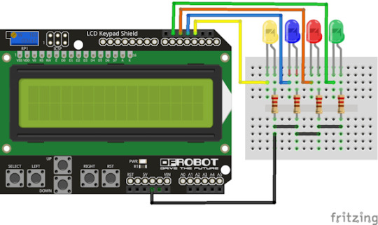
LEDLCD Keypad ShieldGelbD2BlauD3RotD11GrünD12Kathode / GNDGND
Der Quellcode ist etwas länger geworden da ich hier eine Struktur für die LEDs implementiert habe welche die Daten für die Pins, den aktuellen Status sowie den Menüeintrag beinhalten.
struct MenuItem {
int ledPin;
bool ledStatus;
String caption;
};
Damit können wir nun über einen sprechenden Namen auf die jeweilige LED zugreifen aber auch unser Menü aufbauen.
MenuItem mILedGelb = { 2, false, "LED Gelb" };
MenuItem mILedBlau = { 3, false, "LED Blau" };
MenuItem mILedRot = { 11, false, "LED Rot" };
MenuItem mILedGruen = { 12, false, "LED Gruen" };
//maximale Anzahl der Einträge im Array
const int NUM_MENU_ITEMS = 4;
//das Menü
MenuItem menu = { mILedGelb, mILedBlau, mILedRot, mILedGruen };
Der komplette Quellcode zum steuern von LEDs über ein Menü am LCD Keypad Shield:
#include
//initialisieren des Displays
LiquidCrystal lcd(8, 9, 4, 5, 6, 7);
//die Taster sind gemeinsam über den
//analogen Pin A0 angeschlossen
#define taster A0
//analoge Werte der Taster
const int SELECT = 640;
const int LEFT = 409;
const int RIGHT = 0;
const int UP = 99;
const int DOWN = 256;
//Feld für den Wert des Tasters welcher betätigt wurde.
int tasterValue = -1;
//Aufbau des Menüs
//aktueller Index
int index = -1;
//Struktur für ein Menüeintrag
struct MenuItem {
int ledPin; //der Pin der LED
bool ledStatus; //der Status
String caption; //Text für das Menü
};
//initialisieren der Menüeinträge
MenuItem mILedGelb = { 2, false, "LED Gelb" };
MenuItem mILedBlau = { 3, false, "LED Blau" };
MenuItem mILedRot = { 11, false, "LED Rot" };
MenuItem mILedGruen = { 12, false, "LED Gruen" };
//maximale Anzahl der Einträge im Array
const int NUM_MENU_ITEMS = 4;
//das Menü
MenuItem menu = { mILedGelb, mILedBlau, mILedRot, mILedGruen };
void setup() {
//Pins der LEDs als Ausgang definieren
pinMode(mILedGelb.ledPin, OUTPUT);
pinMode(mILedBlau.ledPin, OUTPUT);
pinMode(mILedRot.ledPin, OUTPUT);
pinMode(mILedGruen.ledPin, OUTPUT);
//das LCD-Display hat 2 Zeilen mit maximal 16 Zeichen pro Zeile
lcd.begin(16, 2);
//der Index ist initial auf -1 gesetzt,
//die Funktion displayMenuItem prüft anhand des Indexes und der gegebenen
//Richtung welche Einträge angezeigt werden sollen
displayMenuItem(true, false);
}
void loop() {
//auslesen des analogen Wertes, dieser ändert sich je nach Taster
tasterValue = analogRead(taster);
//prüfen welcher Taster betätigt wurde
switch (tasterValue) {
case UP:
displayMenuItem(false, false);
break;
case DOWN:
displayMenuItem(true, false);
break;
case SELECT:
doSomething();
break;
}
}
//Diese Funktion zeigt zwei Daten auf dem LCD-Display an, abhängig
//von dem Index und der Richtung welche navigiert werden soll.
//Parameter updateOnly steuert ob der Index erhöht oder verringert werden soll,
//bei true wird der Abschnitt übersprungen
void displayMenuItem(bool directionDown, bool updateOnly) {
//leeren des Displays
lcd.clear();
//Zeile 2 soll den Inhalt "-ENDE-" haben wenn das Ende des Menüs erreicht wurde.
String line2 = "-ENDE-";
if (!updateOnly) {
//Wenn der Wert des Parameters
//directionDown Wahr/True ist UND
//der Wert vom index kleiner als die maximale Anzahl der Menüeinträge -1 ist, dann...
if (directionDown && index < NUM_MENU_ITEMS - 1) {
index++;
} else if (!directionDown && index > 0) {
index--;
}
}
//Die erste Zeile enthält den Text aus dem Menü mit dem Wert index.
//Der erste Eintrag im Array hat den Eintrag 0!
MenuItem& itemLine1 = menu;
//prüfen ob das Ende des Menüs / Arrays erreicht wurde
lcd.setCursor(0, 1);
if (index < NUM_MENU_ITEMS - 1) {
MenuItem itemLine2 = menu;
lcd.print(" " + itemLine2.caption + getLEDStatus(itemLine2.ledStatus));
} else {
lcd.print("-ENDE-");
}
//Anzeigen der Daten auf dem Display
lcd.setCursor(0, 0);
lcd.print(">" + itemLine1.caption + getLEDStatus(itemLine1.ledStatus));
Serial.println(itemLine1.ledStatus);
//eine kleine Pause von 250ms um die Taster zu entprellen
delay(250);
}
//Liefert anhand des boolschen Wertes einen Text
//bei true wird " AN",
//bei false wird " AUS" geliefert
String getLEDStatus(bool status) {
String result = " ";
if (status == true) {
result += "AN";
} else {
result += "AUS";
}
return result;
}
//Führt eine Aktion aus
void doSomething() {
//Wichtig ist das wir das MenuItem aus dem Array mit
//einem & entnehmen, damit holen wir uns keine Kopie
//sondern eine Referenz. Dieses wird benötigt, da wir
//den Status der LED togglen und speichern wollen.
MenuItem& item = menu;
//umkehren des Status der LED
item.ledStatus = !item.ledStatus;
//schreiben des aktuellen Status an die LED
digitalWrite(item.ledPin, item.ledStatus);
//aktualisieren des Displays
displayMenuItem(true, true);
//eine kleine Pause von 250ms um die Taster zu entprellen
delay(250);
}
Über das Menü können wir nun jede LED einzeln ansteuern und Aktivieren bzw. Deaktiviern.
Beispiel 3 - schalten von Relais über ein Menü
Ich kann quasi schon den Kommentar erahnen "Wie mache ich das mit Relais?". Daher gleich als nächstes das Beispiel mit einem Relaisshield.
Zunächst passen wir die Struktur des MenuItems für eine allgemeingültige Form an.
//Struktur für ein Menüeintrag
struct MenuItem {
int pin; //der Pin
bool status; //der Status
String caption; //Text für das Menü
};
In meinem Fall erstelle ich zwei Menüeinträge, zum einen für eine Gartenpumpe und für eine Lampe.
//initialisieren der Menüeinträge
MenuItem mI1 = { 2, true, "Gartenpumpe" };
MenuItem mI2 = { 3, true, "Lampe" };
//maximale Anzahl der Einträge im Array
const int NUM_MENU_ITEMS = 2;
//das Menü
MenuItem menu = { mI1, mI2 };
Relais haben eine besonderheit diese sind bei einem aktiven Pin deaktiviert und bei einem deaktivierten Pin aktiviert. Dazu lege ich mir eine Variable an mit welcher man dieses übersteuern kann und somit der Code wiederverwendet werden kann.
bool defaultDeactive = true;
Das macht es nun möglich den Code im grunde zu belassen und wir brauchen lediglich unser Menü aufbauen.
#include
//initialisieren des Displays
LiquidCrystal lcd(8, 9, 4, 5, 6, 7);
//die Taster sind gemeinsam über den
//analogen Pin A0 angeschlossen
#define taster A0
//analoge Werte der Taster
const int SELECT = 640;
const int LEFT = 409;
const int RIGHT = 0;
const int UP = 99;
const int DOWN = 256;
//Feld für den Wert des Tasters welcher betätigt wurde.
Read the full article
0 notes
Text
youtube
In this video, you will learn how servo motors work and how to interface them with Arduino UNO and control their movement using the inbuilt Servo library of Arduino IDE as well as without using the library. You will also learn how to make a Servo Tester.
#arduino#arduinocoding#microcontroller#arduinoproject#arduinoforbeginners#technology#electronics#Youtube
0 notes
Text

CANFDuino - Dual CAN/CANFD Prototyping Platform
The CANFDuino is a complete and ready-to-modify embedded system designed for real-world use, combining multiple essential features into one. It offers dual CAN/CANFD ports, an SD card slot, and plenty of analog and digital I/O. Additionally, it features an onboard prototyping shield for SMT and through-hole components, a rugged aluminum enclosure, and robust connectors.
1 note
·
View note
Text

Arduino Workshop - A Hands-On Introduction With 65 Projects
by John Boxall
ISBN-13: 9781718500587
0 notes
Text
Understanding Arduino Timer Interrupts with Example Code
Learn about timer interrupts in Arduino and their importance in real-time applications. Get practical examples and code snippets for precise, realtime timing solutions.
Arduinos are used in many IoT applications. From blinking LEDs to measuring the angular velocity of a wheel, Arduino is the microcontroller of choice not only for professional developers, but also for beginners who can use the board as a programming playground.
Now there are projects where timing is everything. Real-time applications are systems that require a timely response to external events.…
View On WordPress
0 notes
Text
ESP32 / Arduino IDE
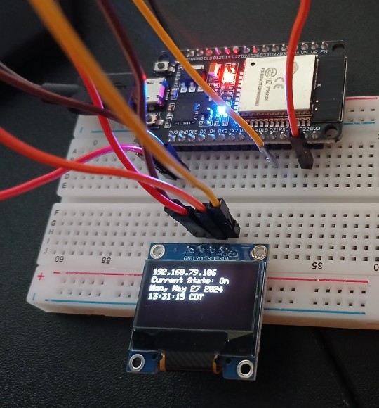
View On WordPress
0 notes
Text
About Arduino Kit
What Is Arduino
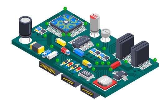
A Microcontroller Board Is A Component Of All Arduino Hardware. It May Be Programmed In A Number Of Languages, Including A Streamlined Version Of The Computer Programming Language C++. Input/Output Pins For Digital And Analog Signals Are Often Included On Arduino Boards. With Which A Variety Of Sensors, Actuators, And Other Electrical Components May Be Interfaced.
The Integrated Development Environment (IDE) For Arduino Is Often Known As The Arduino Software. This Software Gives Arduino Programmers A Simple Interface For Writing And Uploading Code To The Arduino Board. For Troubleshooting And Communicating With The Board, It Comes With A Code Editor, A Compiler, And A Serial Monitor.
The Large User Base And Online Developer Community Of The Arduino Controller Board Is One Of Its Distinguishing Qualities. Giving The Novice Arduino Developer Access To A Huge And Expanding Library Of Arduino Code And Applications. Which Are Openly Shared And Altered. This Makes The Arduino Board A Strong Tool For Testing And Prototyping As Well As Developing Customized Solutions For Particular Requirements Or Applications.
Why Arduino
For A Variety Of Reasons, The Arduino Microcontroller Board Is An Appreciated Hardware Component Among Makers, Hobbyists, And IT Specialists.
Open-Source – The Hardware Computer Programming Platform Arduino Is Free And Open-Source. This Implies That The Public Has Unlimited Access To The Ardunio Hardware And Software Design. This Makes It Simple For An Arduino Developer To Adapt The Platform To Meet Certain Requirements Or Applications.
Usability – The Arduino Microcontroller Board Platform Is Made To Be User-Friendly For Both Novices And Experts. The Arduino Board’s Programming Language, Which Is Entirely Based On C++ Programming Ideas. The New Ardunio Developer Will Find It To Be Rather Straightforward And Simple To Understand. A User-Friendly Interface For Creating And Uploading Code Is Offered By The Arduino IDE. This Is Possible Even Without Previous Programming Knowledge.
Versatility – A Large Range Of Electrical Components, Including Motors, Sensors, And Other Actuators, May Be Controlled By The Arduino Microcontroller Board. Additionally, A Wide Range Of Applications, Such As Iot (Internet Of Things) Projects, Robotics, And Automation, May Use The Arduino Microcontroller Board.
Community – There Are A Lot Of Resources And Support Online For The Big And Vibrant Arduino Community. It Has A User Forum, Arduino Tutorials, And A Code Library. Where Arduino Enthusiasts May Discuss Their New Programming Ideas And Seek Assistance.
In Order To Sum, Arduino Offers An Affordable, User-Friendly, And Flexible Programming Platform For Creating Electronic Projects And Prototypes. This Makes It A Desirable Choice For Both Amateurs And Experts.
Arduino Pros And Cons
Arduino’s Pros.
User-Friendliness – The Arduino Microcontroller Board Is Designed To Be Simple To Use, Even By Novices. The C++ Programming Technology-Based Programming Language Utilized In The Arduino Board. Which A Novice Programmer Or Developer May Learn Rather Quickly. A User-Friendly Interface For Creating And Uploading Software Code Is Offered By The Arduino IDE. This Is Possible Even If You Have No Prior Programming Knowledge.
Affordable – Arduino Boards Are Not Very Expensive. Enabling Them To Be Used By A Variety Of People, Such As Professionals, Students, And Hobbyists.
Versatile – A Broad Variety Of Electrical Components, Including Motors, Sensors, And Other Actuators, May Be Controlled By The Arduino Microcontroller Board. Additionally, A Wide Range Of Projects Including Robotics, Automation, And Iot (Internet Of Things) Can Use The Arduino Board.
Community – There Are A Lot Of Resources And Support Online For The Big And Vibrant Arduino Community. It Features User Forums, Tutorials, And Both New And Old Arduino Code Libraries. Where Arduino Users May Post Questions And Comments.
Continue Reading On — https://vcanhelpsu.com
#arduino#arduinoproject#arduinotutorial#arduinoprogramming#cprogramming#cplusplus#rassbarry#technology#internet#gadjet#developer#webdeveloper#programmer#webdevelopment#programming#coding#tech#programminglanguage#tutorial#code#language
0 notes
Text
youtube
All About IC UNL2003
The UNL2003 IC contains 7 High Voltage, High Current NPN Darlington Transistor Arrays each rated at 50V, 500mA in a 16-pin DIP package. You can connect the IC directly to a digital logic (like Arduino or Raspberry Pi, TTL or 5V CMOS device) without an external dropping resistor. This IC features "common-cathode flyback diodes" for switching inductive loads. The ULN2003 is known for its high current and high voltage capacity.
The Darlington pairs can be "paralleled" for higher current Output.
The inputs are capable with TTL and 5v CMOS logic.
Now, let's deep-dive and check out the internals of the ULN2003 IC and how it can be used in our projects.
0 notes
Text
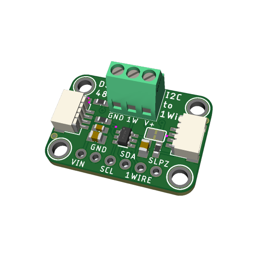
DS2484 I2C to 1-Wire converter
In theory, there's a lot of 1-Wire devices out there, but in reality almost everyone uses 1-Wire for DS18b20 temperature sensors. the long wire lengths and ease of 'chaining' by sharing a single bus wire makes it perfectly fine for this purpose. you can bitbang 1Wire on most microcontrollers, and some SBCs like Raspberry Pi have kernel module support. (https://learn.adafruit.com/adafruits-raspberry-pi-lesson-11-ds18b20-temperature-sensing) But there might be chips without the 1-Wire capability, or maybe you want to use 1-Wire devices on your desktop computer or other SBC with I2C but no 1W.
by special request! this is a DS2484 (https://www.digikey.com/short/5f85v4tf) Stemma QT board that uses the newest I2C-to-1W controller chip, with ESD protection and support for split supplies. you can easily connect it to an existing I2C bus and then use the screw terminals to attach multiple DS18b20's - this library looks promising (https://github.com/pilotak/DS248X) for Arduino. Coming soon!
15 notes
·
View notes
Text
youtube
Push Button Multi LEDs Controller - Switch Case Vs Array Arduino Programming for Beginners
Online Arduino Simulator Virtual Breadboard basic sketch examples: Programming and write Arduino UNO sketch with ezButton Arduino library for controlling LEDs toggle switch ON/OFF with a push button.
#programming#how to#simulator#wokwi#arduino#tutorials#Push Button#LEDs Controller#Virtual Breadboard#Youtube
0 notes
Text
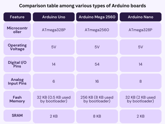
In this article you will learn about Arduino, what’s on the board, different types of Arduino boards available, what can you do with it and its applications.
0 notes
Text
I need to dig out the cheap little General MIDI ROMpler I have tucked away that has a MIDI Thru on it, because I got interesting results out of playing with something else entirely. See, what I was just playing with is one of my very early DIY synth experiments, which I think I called WaxSynth.
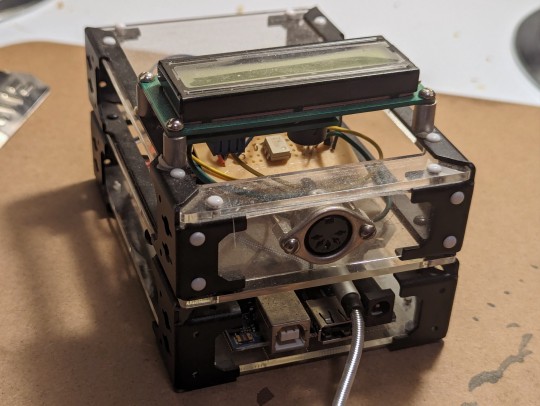
This guy is an Arduino Mega 2560 ADK with a Seeed Studio Music Shield, a MIDI input circuit on protoboard, and a serial LCD display, all put together in a skeletal case system that Radio Shack sold back in the day. The Music Shield is built around the VS1053 audio chip, which is primarily meant to play MP3s but does have a built-in General MIDI synth; you can either throw MIDI files at it or send it real-time MIDI commands, which is what I'm doing here. It's set up so you just plug a keyboard into the MIDI jack, plug it into power, and it'll play audio out the audio jack (the one with the cable plugged in). You can change the instrument either by MIDI commands or via the rocker switch recessed into the left side; the name of the instrument is displayed on the LCD. The patches are generally cheap sounding, but it was pretty amazing to be able to put this together and get it to work all those years ago.
I was looking at this tonight and decided to plug it into my modular synthesizer and play it through different things, and after appropriate boosting of the level, a number of different patches worked. What worked best was running the audio from this into the Hard Sync on my VCO and coercing it into changing a simple monosynth drone into glitchy piano, horn, and organ tones, and even chords, which I did not expect to get out of just sync. The only drawback is of course that once the little MIDI synth stops playing, the drone reasserts itself, and the harmonic clashes are kinda bothersome.
Which is why I need to use the ROMpler with MIDI Thru instead of this guy. I could then also run the same MIDI signal into my Breakout MIDI to CV converter to get note event gates, and use an envelope and VCA to only play the notes while the keys are pressed. I'll try to make a demo recording once I do.
0 notes
Text
Arduino (2024)
5 notes
·
View notes
Text
I'm really tempted to build a radar for radar imaging purposes with an arduino/rpi..
1 note
·
View note
Last Seen Blogs

love-the-bookish-stuff
Bookish stuff


beastlyanachronism
To Meekly Go

glitter-little-cat-blog
*☆* MEAW *☆* welcome to my kingdom

concretedrivewayssydney
Pro Concrete Driveways Sydney