#esp32
Text
Corndog girl fps test
#bocchi the rock!#corndog girl#esp32#the framerate is uncapped#hence why she move so FAST#bocchi the rock
336 notes
·
View notes
Text
(doing something stupid) can you allocate an array at a specific address during compile time in C++. This system is Harva-actually wait the docs say this is almost a built in feature. Hang on.
Hell yes okay I have the thing I want working, you just have to. turn off memory protection and use the IRAM_ATTR thing. That's fine. I think I can make this work I'll just block out a couple kB of nops for my plugins. For a moment there I thought I was going to end up using WASM. I might still, WASM is infinitely safer than this. But this is very funny.
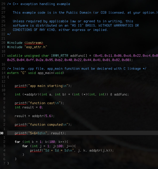
Love function pointer syntax. Makes perfect sense in that awful C way.
That array is just the -O0 implementation of an add in rv32. If you optimize it it's like two instructions but I just wanted to make sure I could execute more than one in a row. I think if you compile right with -fPIC/-fPIE and all that jazz you should just be able to dump that into RAM and execute. Since all your jumps will be relative?
21 notes
·
View notes
Text
playing with my m5 cardputer, wrote a software audio mixing library in micropython and made a crude sequencer with it
14 notes
·
View notes
Text
Protogen Chess
youtube
#furry#fursuit#fursuit friday#protogen#chess#esp32#arduino#furry community#furry fandom#furries#Youtube
10 notes
·
View notes
Text
Desktop portable Stargate 🌌🛸💡
Always liked the episode of SG-1 when Orlin made a mini Stargate using various parts ordered online and from Major Samantha Carter's toaster. This one at least fits in our apartment, all part of the round LCD work we are doing with the ESP32-S3.
#adafruit#arduino#electronics#opensource#opensourcehardware#espressif#esp32#espfriends#display#round#raspberrypi#ICN6211#TFT#RGB#tftdisplays#innovation#screendesign#technews#devboard#uniquedesign#screentech#gadgetlove#futuretech#pcbdesign#rgbdriver#esp32s3#ttldisplay#electronicsengineering#prototype#neopixel
32 notes
·
View notes
Text
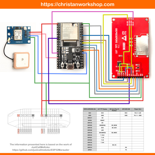
DIY: Marauder with Screen and GPS For Flipper Zero
Many of you would have seen the humongous ESP32 add-on module with touch screen and GPS for Flipper Zero shared in discussion groups, forums, etc. Well, this tutorial will provide you with all the information you need to build one yourself.
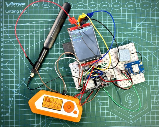
This build consists of mainly 4 parts. The TFT LCD 2.8" 240x320 SPI ILI9341 Touch Display cost me around US$5.50, the ESP32-WROOM-32U module cost around US$3, the NEO-6M GPS module cost around US$2.20 and an 8dbi 2.4GHz Wifi Antenna which cost around US$2. All of these parts can be easily found in online marketplaces like Aliexpress, Amazon, etc.
Here is how you need to wire them up together. How you wish to lay this out or mount on a prototyping board is entirely up to you. As long as the connections are correct, you are good to go. The GPS module is optional, and mainly, it's used for the war driving functionality.
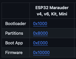
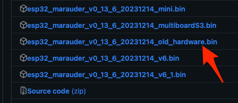
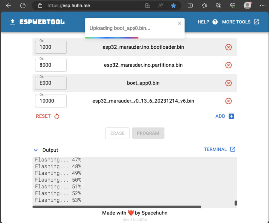
Next, you need to download all the firmware needed from here. Please download the Bootloader, Partitions, Boot App and Firmware files for v4 (Yes, v4 files, not any others) and save it on your computer.
Now, press and hold the BOOT button on your ESP32-WROOM-32U module and connect it to your computer using a data-capable USB cable (some USB cables can only charge), then let go the BOOT button.
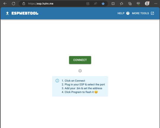
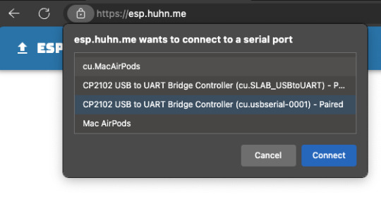
Open Google Chrome or Microsoft Edge browser and go to ESPWebTool. Click the CONNECT button, then select the ESP32 usb serial connection. It should look something like below but can vary a little between different computers and operating systems.
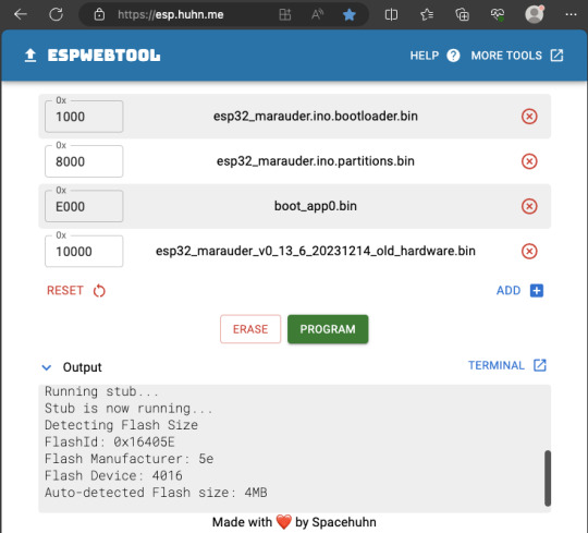
Select the firmware files for each slot exactly like below (take note of the 0x1000, 0x8000, etc. and their corresponding .bin files), then hit the PROGRAM button.
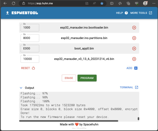
When completed successfully, you can unplug the USB cable from the ESP32 module and now you can connect your Marauder module to your Flipper Zero.
Please ensure that your Flipper Zero is turned off before you connect it, and also turn off your Flipper Zero before disconnecting it. The 3.3V pin is also used by your Flipper Zero's SD card reader and connecting/disconnecting external modules that use this pin while the Flipper Zero is on can potentially corrupt the SD card.
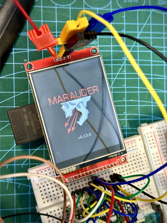
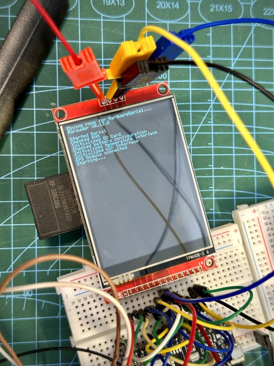
So, if everything went according to plan, your Marauder module should boot up and everything should look like below.
NOTE: If your Marauder boots up, but when you try to touch the screen and get no response, try tapping around the bottom part of your screen and see if the touch panel seems to be in inverted position from the actual display. Should this happen to you, just flash your ESP32 module again following the steps above, but use the v6 firmware. This should resolve the issue.
In this build, I just prototyped this on breadboard, but you can of course make it permanent by soldering it on to a prototype board and 3D print a case for it. This setup is essentially just using the Flipper Zero as a battery pack, instead of using the Flipper Zero to control Marauder.
The large screen does make some things easier to do, compared to the small screen of the Flipper Zero, and there may be some functionality (not much) that is not currently in the Flipper Zero Marauder companion app. Here is a video showing the different menus in Marauder.
Personally, I don't think I will actually want to bring something so big around with me, along with my Flipper Zero. I think what makes Flipper Zero special is just how compact it is and all the different functionality cramped into it. This would probably be better off as a standalone unit by just hooking up a battery, but that's just me.
Well, that's it for this tutorial. I hope you found this helpful.
If you haven’t already done so, check out my Makers & Hackers Exchange Facebook group to learn more from other Flipper Zero users.
Here's a good intro to Marauder if you are unfamiliar.
youtube
7 notes
·
View notes
Text
Local idiot orders Arduino clone without the pins attached, solders them himself, kills the only 5V pin on the board. (all 4 0V pins seem to still work)
4 notes
·
View notes
Text
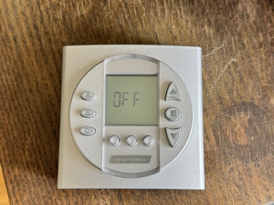
13. April 2024
Die smarte Jalousie
Wir haben eine elektrische Jalousie. Die hält im Sommer die Sonnenwärme draußen und im Winter hat man etwas Sichtschutz und so. Dazu gibt es eine Fernbedienung. Damit ist es leicht, die Jalousie rauf- und runterfahren zu lassen. Weil wir vor ein paar Jahren, als die ganze Technik installiert wurde, auch etwas automatische Steuerung haben wollten, gab es seinerzeit auch eine Schaltuhr dazu.
Ich behaupte, dass ich mich eigentlich nicht besonders dumm anstelle, wenn es darum geht, so eine Schaltuhr zu programmieren. Aber dieses Gerät ist eine einzige Katastrophe. Bis heute ist es mir nicht gelungen, die so zu programmieren, dass die Jalousie dann herauf- und hinunterfährt, wenn sie soll. Zwar meistens, aber nicht zufriedenstellend. Wenn sie einmal funktionierte: Bloß nicht mehr anrühren, bis der Übergang von Sommer zu Winter und umgekehrt Maßnahmen verlangten. Das ist der Übeltäter, hier inzwischen inaktiv:
Zwischenzeitlich übernimmt Apple Homekit einige Funktionen in unserem Haus, z. B. die Steuerung der Warmwasserpumpe. Und da dachte ich, dass ich die Jalousie dort auch andocken könnte. Geht ja auch mit Funk und so. Aber leider ist es etwas undurchschaubar, was man nun für Gerätschaften braucht. Der Hersteller scheint nicht nur bei seinen Bedienungsanleitungen zur Verwirrung zu neigen. Ich bin mir also nicht sicher, ob die Steuerung überhaupt mit Apple Homekit gehen würde.
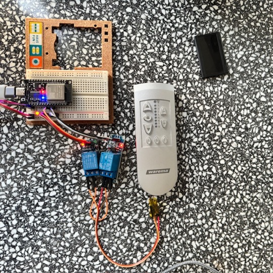
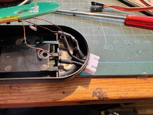
Also suche ich im Internet nach anderen Lösungen. Ein bisschen kann ich mit Arduinos umgehen, und so finde ich eine Lösung, wie man ein ESP32-Board mit Apple Homekit verheiraten kann. Meine Idee: Ich schalte mit dem ESP32 ein paar Optokoppler oder Relais, die so tun, als ob sie die Knöpfe an der Fernbedienung meiner Jalousie drücken. Dafür muss ich allerdings erst mal ziemlich filigrane Drähtchen an den richtigen Stellen der Platine anlöte. Diese Kontakte sind mit den Tastern auf der Platine verbunden.

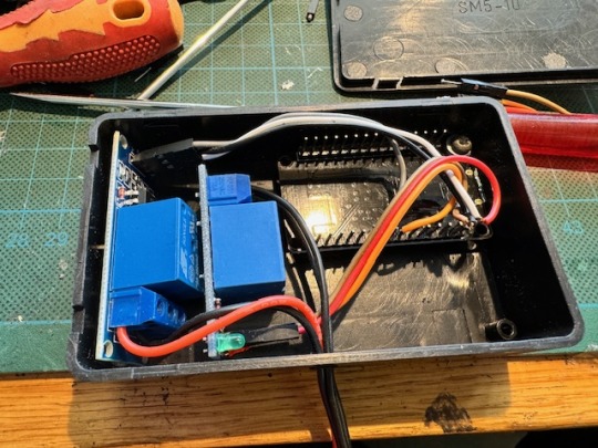
Die Kupferlackdrähte enden dann an zwei Relais am ESP32-Board. Ich stecke das erst mal alles auf einer Steckplatine zusammen. Es funktioniert. Gegen Optokoppler entscheide ich mich, weil vermutlich die zu schaltende Spannung zu gering ist.
Meistens jedenfalls. Denn immer wieder verliert das ESP32-Board die Verbindung zum Homekit-Netzwerk. Auch hier ergoogle ich mir eine Lösung. Die besteht offensichtlich darin, dem WiFi-Router einen festen Kanal zuzuweisen. Ich hoffe, dass damit auch dasselbe Problem mit anderen Geräten passé ist, die sich ebenfalls immer mal wieder aus dem Verbund verabschieden.
Damit das alles besser nutzbar wird, kommt in die Fernbedienung der Jalousie eine Anschlussbuchse und das ESP32-Board mit den Relais in eine kleine Box, aus der das passende Verbindungskabel herausguckt.
Auf den Platinen der Relais befanden sich noch LEDs. Die habe ich aus Stromspargründen entfernt. Man sieht davon ja eh nichts.
Man kann nun die Knöpfe der alte Fernbedienung nach wie vor manuell bedienen, aber die Jalousien auch von der Home-App aus ereignis- oder zeitgesteuert herauf- und hinunter fahren lassen.

(Markus Winninghoff)
4 notes
·
View notes
Text
Cyberjacket update. Managed to get the interrupts working, meaning that I have functional buttons even with effects. I can now add as many effects as I have buttons, which is to say: a fucking lot.
#cyberpunk#cyberpunk aesthetic#personal project#cyberjacket#ledstrips#microcontrollers#arduino#esp32#electronics#arduino_language#rgb
3 notes
·
View notes
Text
Devlopment board
#controller#esp32#esp32project#pcb#pcbdesign#pcbassembly#engineer#engineering#electricalengineering#circuits#iot#smarthome#diyelectronics#trending#viral#reels#instagram#instragramreels#followers#boost#explore#explorepage#likeforlikes#electricalengineer#electricalwork#electricalcontractor#electricalhacks#electricallife#electricalsky
2 notes
·
View notes
Text
2 notes
·
View notes
Text
Moisture sensor development - 2022/23
Multiple sensors have been running over winter 22 to summer 23 and some problems have arisen:
One temperature sensor stopped functioning but in a way that eluded the error detection. The symptom was that the two sensors showed exactly the same measurement. This turned out to be a configuration issue, where both sensor were mapped to the same temperature.
Battery life was too short on a couple of sensors. This may be because of poor quality batteries, poor connections in the battery holder or due to excess drain somewhere. After experimentation with better quality batteries (Samsung 25R rated at 2500 mAh) it seems the main problem is poor quality batteries.
Moisture sensors losing discrimination. On a new sensor the range from wet to dry is typically 900 but this reduced to 270. I found that cleaning off the old silicon sealant, cleaning the board and resealing brought the readings back to normal.
Moisture sensor connection. The waterproofing with silicon and the JST connector are a poor design. Securing this connector with a zip tie helps to secure this connector.
Rusty main board. One device failed due to rust getting into the pins and socket on the main board connector. This is evidence of moisture in the device container. The sensor cable entrance is sealed with a large amount of silicon sealant which often fails. However when a second device also failed, having drained new , quality batteries very quickly, it seems that the idea of using socket strips on an outdoor device, however well sealed, is a mistake. In any case the board and the chip are really the only significant components so they may as well be soldered together.
One sensor on a public Tiny Forest was stolen. This despite being well - hidden and having a notice inside the box explaining the scientific purpose of the device.
I had considered changing the design of the PCB to avoid the use of a ground plane since I found this made soldering to ground terminals difficult and poor connections created problems. On reflection, my problem is probably insufficient thermal inertia in my small iron and the use of a better, temperature-controlled iron would solve this issue whilst retaining the benefits of a ground plane.
Labels printed on a label printer fade very quickly in sunlight.
An error in the code for the test phase meant that sleep time could be negative with odd results.
It has been suggested that over-the-wire updating of the code should be implemented but I am concerned about the current demand,
Improvements
Have a working set of all three sensors which can be plugged into a device to check the cause of a failed sensor.
Replace the cheap 18650 batteries with Samsung 25R flat top batteries.
Solder the chip directly to the PCB instead of using a socket strip
Develop a better sealing system for the cable entry.
Use a chinagraph pen for labeling
Reconsider strategy for protecting devices in public places
3 notes
·
View notes
Text
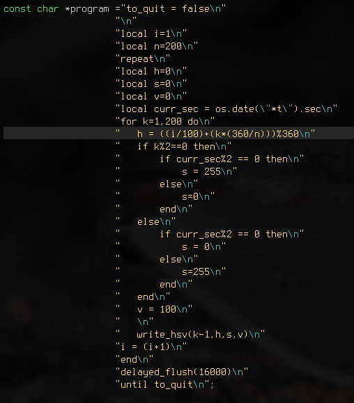
oh hey that makes sense. I have NTP coming in to this microcontroller over wifi and you can just... make os.date() calls from Lua to get the current time of day, because that goes through to the C calls, and the ESP-IDF implements all the standard time functions. Cool as hell. That really simplifies a lot of my life by moving yet more stuff into lua.
I was expecting this to require way more painful munging of data but it's very smooth and you can basically just write lua. I have a function that delays your pixel write until the next frame and it just works. I keep track of the number of microseconds you had "left" to draw before delays start happening so I can generate utilization stats, and because Lua gets its own entire core there's not really any noisy neighbours to cause jitter (which I noticed before I moved the wifi thread over)
Now for the hardest part: making an interactive webpage that is not piss. At the last work conference one of my coworkers was showing off her plugin for a docker webui and a bunch of kernel developers were like this is great but I will never send you a patch for this because the browser DOM confuses and terrifies me. And I agree with this sentiment.
14 notes
·
View notes
Text
USB-BLE MIDIインターフェイスを作る② - iOSのBLE MIDI接続設定を調べる
USB-BLE MIDIインターフェイスを作る際に気になる遅延とiOSの接続設定の話です。
前回のお話:
無線MIDI接続を利用する際に気になってしまうのが反応の鈍さではないでしょうか。鍵盤を押してから音が鳴るまでに一瞬でも間があったり、ジャストなタイミングで弾いているはずなのになぜか音がずれる、的なことがあると致命的です。
BLEの技術的な話
Bluetooth LE(BLE)では、親機(セントラル)と子機(ペリフェラル)という概念があり、たとえばiOS機器とBLE MIDI機器を接続する場合はiOS側がセントラル、BLE MIDI機器がペリフェラルになります。BLEが特徴的なのは、セントラルが出した信号に対しペリフェラルが応答する形でデータを送信するという形態です。つまり、セントラルが信号を出さない限り、ペリフェラルからデータを送ることができないのです。通常セントラルは一定間隔でペリフェラルに対し信号を送信しますが、この間隔(Connection interval、Interval)はセントラル側に決定権があります。ペリフェラル側からも、「こういう間隔で信号を送って欲しい」という要望をセントラル側に送信することはできますが、その要望通りのIntervalを利用するかどうかはセントラル側が決定します。
ちなみに、BLEでの接続パラメータはIntervalに加えて「Connection slave latency(Latency)」と「Connestion supervision timeout(Timeout)」というものもあります。セントラルが信号を送信した際に、ペリフェラルはその信号を無視することもできるのですが、Latencyはこの無視できる回数の最大数を指定するパラメータです。また、Timeoutは接続が失われたと判断する時間を指定するパラメータで、通信を行えずにここで指定した時間が経過すると、通信の切断を行います。
これらのパラメータとして指定できる値は規格で決まっており、Intervalは規格上は最短7.5ミリ秒、最長4秒、1.25ミリ秒の倍数、と決まっています。また、Latencyは0以上500以下(かつTimeout/Intervalより小さい値)、Timeoutは最短100ミリ秒、最長32秒、10ミリ秒の倍数です。また、Intervalの値をリクエストする際には最小値(Min)と最大値(Max)を指定する形になっています(つまり、ペリフェラル側がセントラル側にパラメータ設定をリクエストする際はInterval Max、Interval Min、Latency、Timeoutの4つのパラメータを指定する)。
BLEでは7.5ミリ秒より短い間隔での通信は行えないため、規格上は少なくとも7.5ミリ秒の遅延が発生する可能性があります。さらに、iOSではBLEに関する独自の制約があります。これによると、Interval Minは15ミリ秒以上(かつ15ミリ秒の倍数)、Interval MaxはInterval Max+15ミリ秒以上(た��し15ミリ秒は許容)などとなっています(詳しくはAppleのドキュメントを参照)。ということで、iOSデバイスと通信する場合、どう頑張っても最長15ミリ秒の遅延が発生することになります。
実際の接続パラメータを調べてみる
さて、ここまではあくまで仕様上の話で、実際にiOSでBLE MIDI接続を利用する場合に、どういった接続パラメータが利用されるかは公表されていないようです。ということで、iOSデバイスとBLE MIDIデバイスを実際に接続して接続パラメータを調べたり、接続パラメータ変更リクエストが受け入れられるかをチェックしてみました。
基本的なコードは前回記事で使ったものと同じですが、ここで使用しているArduino BLE-MIDI Transportには、BLEの接続パラメータ変更機能がありません。ということで、Arduino BLE-MIDI Transportのコードをコピペして、接続時やデータを受け取った際に処理を追加できるように改造した「BLEMIDI_ESP32_NimBLE_Custom」というclassを作成しました(本来は継承したclassを作るべきなのでしょうが、コードが煩雑になりそうだったのでコピペで作成)。
このクラスはテンプレート引数でBLEServerCallbacksクラスの派生クラスとBLECharacteristicCallbacksクラスの派生クラスを指定するようになっており、接続時や各種イベント発生時にこのクラスで実装したコールバックメソッドが呼ばれる仕組みです。
メインのコード(ble_midi.ino)では(テスト目的なので)USB MIDI関連のコードをコメントアウトし、代わりにシリアル通信でBLE関連のイベント発生時に接続パラメータを送信するように実装しています。これは、EPS32 Arduinoで用意されているlog_i()の関数を使っています。この関数を実行すると、USBシリアル通信経由で指定した値がログとして送信されます(この機能を利用する場合、Arduinoの設定でUSB Modeを「Hardware CDC and JTAG」に、「Core Debug Level」を「Info」以上に設定する必要があります)。
ちなみに、NimBLE-Arduinoはデフォルトでログ用のコードが実装されており、「Core Debug Level」の値に応じてUSBシリアルでデバッグ情報を送信してくれます。便利!
テスト結果
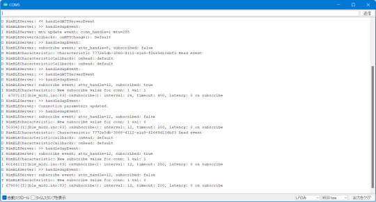
まず、接続パラメータの変更リクエストを送信しないケースでは、接続時の接続パラメータはIntervalが30ミリ秒(1.25ミリ秒×24)、Timeoutが720ミリ秒(10ミリ秒×72)、Latencyが0となっていました(Intervalの単位は1.25ミリ秒、Timeoutの単位は10ミリ秒なので、取得した値にそれぞれ1.25、10を掛けた値が実際の時間になります)。
[ 13624][I][ble_midi.ino:49] onConnect(): interval: 24, timeout: 72, latency: 0 on startup
その後、こちらからは接続パラメータの変更要求を出していないにも関わらず、接続パラメータの変更が行われました。変更後の値はIntervalが15ミリ秒(1.25ミリ秒×12)、Timeoutが2秒(10ミリ秒×200)、Latencyが0となっていました
D NimBLEServer: >> handleGapEvent:
D NimBLEServer: Connection parameters updated.
D NimBLEServer: >> handleGapEvent:
I NimBLEServer: subscribe event; attr_handle=12, subscribed: false
I NimBLECharacteristic: New subscribe value for conn: 1 val: 0
[ 20477][I][ble_midi.ino:83] onSubscribe(): interval: 12, timeout: 200, latency: 0 on subscribe
これはあくまで想像なのですが、BLE MIDIはリアルタイム性が求められるため、iOS側でBLE MIDIデバイスに対してはデフォルトでこの値を利用するように決められているのではないかと思います。
また、接続時に接続パラメータの変更リクエストを送信した場合についても同様に確認してみました(コード上でコメントアウトしている「pServer->updateConnParams(desc->conn_handle, 15, 15, 0, 400);」の部分が変更リクエストを送信するメソッド)。
まず、iOSのドキュメントで定められている接続パラメータに則った値で接続パラメータの変更リクエストを送信した場合ですが、この場合はそこで指定された値に接続パラメータがセットされました。たとえば「Interval Min=12, Interval Max=12, Timeout=400, latency=0」でリクエストした場合、次のような値に設定されています。
[ 23490][I][ble_midi.ino:80] onSubscribe(): interval: 12, timeout: 400, latency: 0 on subscribe
「Interval Min=48, Interval Max=72, Timeout=400, latency=0」のように、15ミリ秒より大きい値を指定した場合は、Interval Maxで指定した値が設定されました。
[ 17025][I][ble_midi.ino:81] onSubscribe(): interval: 72, timeout: 400, latency: 0 on subscribe
また、iOSのドキュメントで定められている接続パラメータに適合しない「Interval Min=6, Interval Max=8, Timeout=400, latency=0」という値を指定した際は、指定したIntervalには設定されず、代わりにIntervalとして24が使われました。
[ 27836][I][ble_midi.ino:80] onSubscribe(): interval: 24, timeout: 400, latency: 0 on subscribe
接続直後のIntervalの値が24(1.25×24ミリ秒=30ミリ秒)なので、これがiOSのデフォルト値で、適切でないIntervalが指定されるとこの値が使用されるように見えます。
結論
ということで、少なくともiOSでBLE MIDI機器を利用する場合、特に機器が接続パラメータの変更をリクエストしなくとも、15ミリ秒間隔で通信するように設定されるということが分かりました。つまり、前回テストした際もiOSでの最短Intervalである15ミリ秒間隔で通信が行われていたわけで、そこで発生した遅延は少なくとも接続設定変更では解決できないように思われます。
4 notes
·
View notes
Text
Playable version of The Witness on a Protogen. (ESP32 Connected via LAN)
4 notes
·
View notes
Text
ESP32 ItsyBitsy is in final testing zOne!
OK, after a long hiatus, the ESP32 Itsy Bitsy prototypes are built and ready for testing! We first designed this board Feb 20, 2020 - and it's been waiting oh so patiently for its turn. The ESP32 Pico module packs 8 MB of flash and 2 MB of PSRAM. Despite its small size this board can handle fairly complex programs. This board is very small but has lots of pins, with a USB-serial converter, NeoPixel, reset and user button, Stemma QT connector, and a 5V-logic output specifically for driving NeoPixels. to do my final 'all in one' test we're reading temperature and humidity from an I2C sensor, sending it to IO, then reading back the onboard NeoPixel color from the dashboard. It's an excellent way to make sure the whole thing is working the way we like. Last up, we'll do a low-power test, and then it'll be ready for fabrication!
#espressif#esp32#adafruit#ItsyBitsy#NeoPixel#hardwaretesting#pcbdesign#micropython#iotprojects#embeddedsystems#prototyping#makersmovement#technologyinnovation#electronicengineering#diyelectronics
7 notes
·
View notes
Last Seen Blogs

paaaaating
Little Princess

yg-seikai-blog
幽玄星海

norahalib
THE ULTIMATE FANGIRL

senpai-plz34
senpai?

hypersexualitycontain3d
A Witch