
studioboytimes
Studio Boytimes
Tracking, Mixing, "finalization", amp repair/mods, custom pedals/mods and all other things audio
in beautiful Saint John, New Brunswick Canada
53 posts
Don't wanna be here? Send us removal request.
Last Seen Blogs

uknowmarcus
uknowmarcus

mayor-asa
~ Asa of Fjörgyn ~


redballoon1761
Sexy Anatomy

thedeathdeelers
bro
Text
Traynor YGL-3 Upgrades & Mods
Hey! I got myself a second mid-seventies YGL-3 combo! This one has two Weber speakers, and otherwise was almost totally bone-stock. I did all the usual upgrades and made a few mods. Documented below are the changes I’ve made.
Change Phase Inverter to Fender Twin specs:
Change tube to 12AT7
Change bias feed resistors from 100K to 220K
Change NFB resistor from 1K (though there was a mistake on a lot of boards where this is actually a 100R!!! Both of mine featured this error) to 820R
Change 470K grid resistors to 1M
Change tone stack:
Replace ceramic caps with film (not because they “sound better” but because ceramics often go microphonic. Best to avoid that.)
Replace 47n cap with 22n cap for bigger bass response
Change power section:
Replace 47R screen resistors with 470R 5W cement resistors. If you’re not lazy, use one 470R per tube, in addition to the master 470R 10W
Disconnect the bias supply from Pin 1 of each tube and connect Pin 1 to ground (you can just jumper to Pin 8) so you can use 6L6 if ya want
Change PSU:
Remove the 47n to ground resistor on the Ground switch
Rewire the mains so that the power switch is first, circuit breaker second
Ensure mains polarity is correct and that the HOT side is connected to the breaker
Replace 40u 450V paper roll caps with 47u 500V caps
Replace preamp filters with 22u 450V
Replace 6BQ5 filter with 10u 350V
Change bias circuit:
Change 8u 250V cap with a 10u 100V
Change 64u 100V with a 100u 100V
Replace 22K series resistor with 17K2 (series connect a 15K and 2K2). This allows enough of a range to bias either 6L6 (around -50V) and 6CA7 (around 37V)
Misc changes:
Replace V4 (reverb recovery) with 12AT7. Just personal preference here.
Change trem oscillator caps from 10n to 15n for a slower speed (again, personal preference)
Combine Trem/verb footswitch jacks to a single Cliff jack (reverb on the tip, trem on the ring)
Remove internal speaker wiring and put a right angle 1/4 inch jack on it (so it’s easier to remove to work on, and also so you can use an external cab)
Add a 180R 20W from tip to ground on the speaker output. If you want you can swap the jack for a switched jack, and put the resistor on the switch so it’s switched out when the speakers are plugged in
Replace trem cathode resistor with a red LED, which you can mount on the chassis panel (I put mine between the speed and intensity controls)
Remove thermistors (if present - sometimes they aren’t)
3 notes
·
View notes
Photo

So I just cracked this open. It used to be a 60s Fender Princeton. It has the transformers from a twin, 4x6L6GCs, a standby, line out, and obviously, a completely rebuilt circuit and power supply, including one can cab that is strapped to the inside of the cabinet. Wow. Just, wow.
3 notes
·
View notes
Photo
This is a fairly common mod for feedback loop clipped OD circuits, with a nice explanation for the kids, and schematic to boot. Do this to your rat (the 2u2 replacement that is).
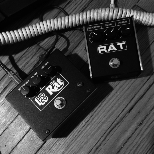
Darrell rants about the Proco Rat and the ruetz mod.
It’s no secret that the rat is my favourite pedal to ever exist. It’s only drawback is the fact that it can cut a bit too much bottom end for use with low tuned instruments such as baritone guitars, heavily detuned guitars, or bass. The most common mod to remedy this is the ruetz mod. It was the first pedal mod I ever did and the thing that got me hooked on messing around inside pedals. I’ve played around with this mod and the whole rat circuit a ton and am obsessive about getting as much usable low end as possible out of every pedal.
The ruetz mod basically consists of messing around with the 47ohm resistor (R6) that is part of one of two rc (resistor/capacitor) filter networks from the opamps feedback loop to ground. Sometimes this resistor is literally just snipped leaving only the 560ohm/4u7 rc pair to set the gain and low end roll off. Other times that 47 ohm resistor is replaced with a pot. Usually around 1k.
My problem with both versions is that bass is never actually increased. Instead the gain of treble frequencies is actually being decreased by varying degrees. This does give the perception of more low end but in my opinion the decrease of gain in the high end actually robs the rat of its true character. The are tons of “boutique” rat derivatives and rat inspired pedals out there that incorporate some version of the ruetz mod and it boggles my mind.
So what’s the solution?
Well if you know anything about rc filters and especially rc filters in opamp based dirt circuits, you know that the capacitor in that rc pair has an equal impact on the frequencies amplified by the opamp which are then clipped by the diodes. Typically the resistor sets the gain and that resistors relation to the capacitor sets the frequency roll off.
If we look into the rc filters in a rat we’ll see that the 47ohm/2u2 rc pair sets one high pass filter roll off at around 1500hz while the 560ohm/4u7 pair sets a second roll off point around 60hz although with much lower gain.
There are tons of popular mods for equally classic pedals (tubescreamer, distortion plus etc) that involve tweaking the value of the cap in the opamps rc filter to get more bass out of the circuit while leaving gain levels alone.
So why does that seem uncommon in a rat circuit? Why do we ignore the capacitors?
Because I don’t think anyone has written it on the internet yet and a large part of the boutique/DIY pedal community can’t do anything until someone else does it first and tells them how it’s done. The idea of understanding concepts applicable across the board is just beyond some.
So back to these rc pairs…
My favourite version of the ruetz mod was always just replacing the 47ohm resistor with something around 400 ohms which gives a roll off about 180hz while sacrificing a fair bit of gain but If you increase the value of the 2u2 cap instead you can get your low end back without sacrificing ANY gain. 22uf will give you a roll off of around 150hz which is low enough to let most bass frequencies through without getting muddy.
If you want a tweakable version you could wire up a capacitor blend pot (usually used at the input or output of a circuit) to blend between the stock 2u2 and a much larger cap or any 2 values you want. I’ve used this in several of my own builds and it is massively usable.
Leaving the amount of gain in the circuit alone also makes diode changes much more obvious. Put a big cap (or cap blend pot) in there and a 3 way diode toggle (or even a diode blend pot) and you’ve got a super flexible rat that still has all the amazing qualities of the best rats.
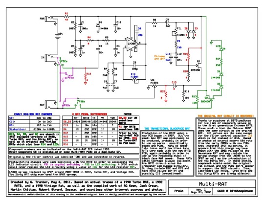
Also check out the comparative rat schematic demonstrating why the “vintage” rat circuit isn’t all that special (with the exception of the lm308). It’d take anyone who can solder 20 minutes or less to covert any rat to vintage specs. My rat 2 was already “vintage spec” other than the missing lm308.
Rats rule.
Use your head.
End rant.
96 notes
·
View notes
Link
Finally, a sexy as hell web app to view the Earshot! charts! Bookmark this site immediately!
0 notes
Text
Another Weird Canadian Handmade Stencil
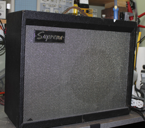
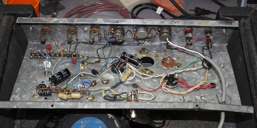
This time, a "Supreme"; made in Canada by Garnet in Winnipeg in the late 60's, and sporting a strange enough tube compliment of an 5AR4 rectifier, a 12AX7 (using only one triode), two 6AV6 dual-diode & single triode, and a single 6V6 for the output.
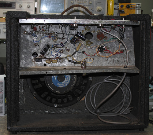
When this came to me from a good friend of mine, it was missing the back panel and most of the tubes. It was all original inside, though someone had been in there, having removed the middle input jack, for what reason we will never know. Meanwhile, all the caps and carbon resistors were left in place.
Some wires and solders had come loose or gone cold, and the power tube that was installed was - amazingly - a 50V6; basically a 6V6 with a 50V heater. If that ever actually worked in this amp, I don't know how.
The speaker leads were frayed and thin, and the cheap-ass little speaker was held together with silicone glue and tape.
Of course, I neglected to take a before picture, so you'll just have to take my word for it.
This guy got a run up and down, but I didn't change anything that didn't NEED to be changed. Yes, I even left carbon comp plate load resistors. They didn't crackle, so I didn't replace. Plus, according to Zach Vex, "Crackle OK!"
The amp got a 3 prong power cable with the ground to chassis. Then it got all new electrolytics top to bottom. The two tube sockets for the 6AV6's were so worn out that I couldn't even retension the pins, so they were both replaced, with nicer, shielded sockets. Naturally, the pinout was a different orientation, so I had to rewire every connection back to the pins. I replaced the original carbon cathode resistors with metal film, since I already had them lifted anyway.
The bad speaker lead was soldered to the driver tabs, then came up through a hole in the chassis, then connected to the output transformer leads. I assume that there was a jack there before, so I put a new jack on her, and wired the trafo up to the jack. There was a spare OT secondary taped up, but I didn't bother to measure it or hook it up. A nice Neutrik right angle jack on some nice new zipcord, and some crimped & soldered spade connectors, along with an old Fender branded Oxford with a small hole in the cone finished off the output section.
The pots were all dirty, so I gave them a GOOD flush out with Deoxit D5, let it dry a few days, then a quick coat of F5, for added lubrication. I LOVE that F5 stuff, but the D5 is really good at flushing out major gunk. They make an excellent team.
On the first power up, there was no audio. Everything seemed ok voltage wise, and then I realized that I forgot the cathode resistor for the first stage. Opps! After I added that we were off to the races.
For such a small amp (3ish watts), the thing REALLY sings. With a thick low-mid and no harshness on top, I was surprised by how much weight the sound had. Also, VERY little hum for a single ended amp. The tone control was much like that of the early Fenders (read: Harvard), and worked well on this amp. With my Univox Les Paul copy I was using I was able to get a tamed balanced tone on the muddy neck pickup, and a thick and full not nasally bridge sound.Oh yeah, and the bias wiggle trem actually worked too. I never seem to have good luck with 6AV6 trem circuits.
You may be able to tell from the picture, but for the 99.99% of you, the trem was switched on by means of a SPST switch on the back of the trem pot that connects a 2K2 resistor and a 25uf @ 25V cap to ground! You guessed it, the other end of that pair is connected to the cathode of the oscillator! Cool idea, and it works well.
I capped it of by replacing the missing knob with an old skirted guitar volume knob (even conveniently labeled "Volume"), and bolted the chassis onto the cabinet (there also wasn't any mounting hardware with it).
All in all a very nice little amp, considering how piss-poor the construction and build materials were. These little puppies were built to sell, at a major department store near you. I can't imagine the designers and marketers of these little rigs would have ever imagined in their wildest dreams that these thing would still be in use some 50 years (or more!) later, and even more shocking would be the fact that people like the way they sound.
4 notes
·
View notes
Photo

This 60’s YBA-3 was completely submerged under water during a basement flood. 4 days later you’d never know it had been wet.
It’s in for the full meal deal. New tubes, caps, 3 prong power cable, a new power tube socket that got burned up before the flood, and any water damaged components. Though I have a feeling all is well otherwise. Traynor: built to outlast the cockroach after the apocalypse.
Update:
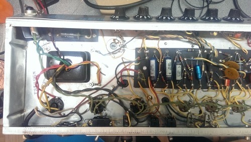
This is the ORIGINAL model of the YBA-3. There are at least 4 different variations on this amp, but this one was the first, originally set up with 7027A power tubes, no master volume, and no bias pot. This model also uses one less gain stage than later models, meaning there's an unused half of a 12AX7 just sitting there waiting to be used.
This YBA-3 is being set up to be a guitar amp, so I decided to leave the amp setup for 6L6s, and assume I'm going to have to make some additional changes to the preamps and/or PI (but we'll get into that later). This was a good decision, since the existing tube sockets had their pin 1 removed, meaning to switch to 6CA7/EL34's, I'd have to replace all the tube sockets. If I REALLY wanted it to be a Traynor, I'd also have to add the bias supply to to pin 1 rather than ground. Ohhhh Traynor...
After allowing the amp about 2 weeks to FULLY dry out (mostly worried about moisture inside the transformer windings), I got down and dirty in this old gal.
First thing I noticed was that you'd barely be able to tell this thing had ever been wet. The old paper caps looked discoloured, and the tagboard was quite warped, but otherwise, you'd never know.
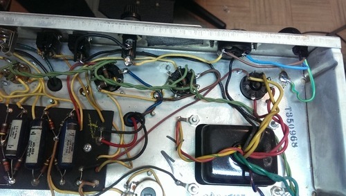
Some of the pots were ceased right up, but a few squirts of Deoxit F5 (the fader stuff) had them moving freely. While I was at it, I filed all the jacks, and cleaned with more Deoxit F5.
After inspecting all the wire connections and solder joints I only found one resistor leg that had pulled loose due to the tagboard warpage. Not bad!
Not sure how this would have happened, but the cathode of the 4th power tube wasn't connected to anything, so that tube would have been effectively out of circuit. Hmmmm...
A mod had been done to the phase inverter, made obvious by the two big Orange Drop decoupling caps. Someone made a boo-boo there, and only had 1K5 grid stopper resistors going to one tube per pair. The other tubes were getting a direct feed from the audio/bias supply node. Opps! Also, one existing 1K5 was carbon comp, so I ditched that and replaced with metal film.
Then, I replaced all the electrolytic caps. I managed to reuse the side terminals used to series connect the big 80/450V caps and 100K balancing resistors. As usual, instead of removing the old can caps, I just unhooked them and left the cans and bleeder resistors in place. Why bother with that business?
The new caps replacing the dual 40@450V cans were twisted together, strapped with a 100K 1W resistor and soldered to chassis. Nice and strong.
The tube socket of V3 had burned up, melting off it's screen and plate pins, so I replaced it with a nice NOS phenolic socket (as the ceramic socket I had was too skinny for the chassis! It fell right through the hole).
I touched up the solders to chassis where the cathodes were connected, as someone had blobbed up on top of the existing solder with an under-powered iron. Seriously kids, if you want to work on these amps, you HAVE to have a high-power iron with a big flat tip.
Before powering up, I replaced the original 2 wire power cord with a nice new molded end 3 prong, and soldered the ground to chassis, of course. While I was at it, I reversed the power leads, as the "hot" side of the line was connected directly to the trafo primary, and the "neutral" side to fuse/switch/trafo. Now, "hot" goes to the fuse/switch.
The mains power switch was bad, so it was replaced with the ground switch, which I also had removed. It's nice to recycle when you can.
The mains fuse was - unsurprisingly - blown, so it was replaced.
Now ready to power up, I plugged the amp into my special limiter: a normal duplex 120V outlet wired in series with a 60 watt incandescent light bulb. This is an important device for testing an amp that may have a bad power tube, or a short somewhere in the power supply. Here's how it works:
Since the device under test (the amp) is connected in series THROUGH the light bulb, then to the wall, when you power up the amp, it PULLS its power through the light bulb. When you power up the amp, the heater lines start drawing current to power the heaters (if any tubes are installed). Also, the HV circuit energizes and attempts to fill the supply caps. When you flip the switch to "ON", the amp starts pulling current, and the light bulb will light up BRIGHT. The bulb lighting raises it's internal resistance, dropping the voltage available to the amp, thus limiting the amount of current the amp can draw. As the amp draws less current after the caps charge up, and the heaters warm, the bulb dims to almost off.
If there is a short in the power supply, the light will stay lit bright, as the amp attempts to dump all that current right to ground. If there is no short, and the amp is operating normally, the bulb will dim, and the available voltage to the amp will go up.
So, if there's a short, it will light right up, and be very visible, it will save you popping a fuse, and it will prevent the amp from doing any damage to itself. Cool eh? I also have a lower tech version which is just a 60 watt bulb with alligator clips so I can clip it right onto the fuse holder. This is only useful on the old amps where the fuse holder has exposed pins.
One downside is that there is always some inherent loss while plugged in to the bulb, thus, it's not possible to get accurate voltage readings inside the amp. Several times I have forgotten to unplug the amp from the bulb and was flabbergasted when I measured only 4V on the heaters. Opps! Use it to check for shorts, then assume everything is ok enough to go full power.
Luckily, this old beauty powered up fine, not showing any signs of shorts or issues.
With power but without the power tubes, I measured the bias supply, and found it to be off of where I figured a good starting point would be. The voltages in the amp were about 20% higher than indicated on the schematic, due to the mains voltage slowly creeping up since the 60's (originally 115V, now around 121V at my shop).
I changed the bias voltage set resistor to a 47K, and added a 25K pot. Now I could get the voltage into a very safe range. A must since the poor 6L6's are taking a very high plate voltage. The modern 7027A tubes are identical in construction to a modern 6L6GC, and thus are not technically rated to take this high voltage, but I know from experience that these tubes will stand up quite nicely to these high voltages.
The screen voltage was only measuring about 0.5V less than the plate voltage, and each tube only had 470R on each screen, so I decided to add a 1K 5W resistor to feed the 4x470R's. This dropped a little voltage, and also added some more protection to the screens. It paid off, because I didn't see ANY glow in the screens. Surprised was I!
The power tubes being installed were Ruby 6L6GCMSTR - a robust and quality tube made in the Shuguang factory (nothing but good reports from these guys!). They are used a lot in Mesa amps, and are supposed to be a drop-in replacement for 6550's, so they gottsta take a whoopin'!
Biased up real "cold" according to the original schematic, and the waveform looked great, lacking crossover distortion or hum. Just fine! Don't listen to the papers (or internet forums), listen to your test equipment and ears! Like a snowflake, every set of tubes is different.
All powered up and running, I go to measure the total power, and am shocked to see a max of around 60 watts RMS clean output.
This amp had been designed with VERY low gain gain stages. Two of three stages are unbypassed and use 22K plate resistors! Woah... not to mention the phase inverter/negative feedback were tuned for absolute minimum distortion.
I fixed up all the gain stages and PI/NFB to be more in line with any Traynor guitar amp (read: any Blackface Fender amp), and voila: tons of available gain to drive those output tubes.
Now doing around 98 watts clean, and over 160 at heavy distortion! Wow! Even pushing that hard, those 6L6's screens weren't lighting up at all. Primo!
And that was it! Very little work considering this thing was completely submerged in water just a few short weeks ago.
Update 2:
After this blog post went up, the owner wrote back to me to relay a story passed to him via his father - the original owner of the amp, and I thought I'd share it here:
The blog is great. My Dad got a kick out of reading it, got more out of it than me trying to relay what was done. He told me a story that was quite interesting. After you told me about the grid stopper resistors [missing from two tubes] and stated that I won’t be able to hear CFBC through the cab. He stated one night when he was practising, depending on how he turned his bass he could hear “Moscow Radio”. I thought was pretty neat, but now no more Moscow Radio.
3 notes
·
View notes
Link
This guy has some great info and examples.
How to design valve guitar amplifiers, from the power supply to output stage and pre amp
For future reference, also has really good stuff about power supplies.
9 notes
·
View notes
Link
R.G Keen - master of audio electronics does it again. I've saved myself two transformer replacements that I otherwise *may* have done were it not for this trick.
As usual, the way R.G explains it just about anyone can understand what's happening. Masterful.
1 note
·
View note
Photo
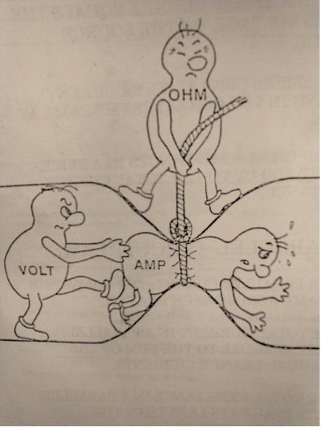
It doesn't get much easier to visualize than this, kids.
111 notes
·
View notes
Link
Here's a really cool old video from (I'm guessing) the 50's explaining how tube amplification works. It explains bias, plate/cathode relationships, how to do most measurements... all the good stuff! Definitely worth a watch.
(Also, this is supposedly voiced by Walter Pidgeon, a famous actor born in my hometown of Saint John, New Brunswick Canada. Cool!)
1 note
·
View note
Link
Fender Blues Junior modification kits and services
This site is just awesome! If you're a BJ owner, you will probably find everything you've ever wanted to know about your amp and more. Inspiration for mods is just a click away. Aspiring techs will appreciate the clear, concise, plain english used to explain the technical principles of the inner workings of the amps.
Not just for BJ owners: the notes, principles, mods, techniques, etc can be applied to just about any amplifier, you know, where applicable.
5 notes
·
View notes
Text
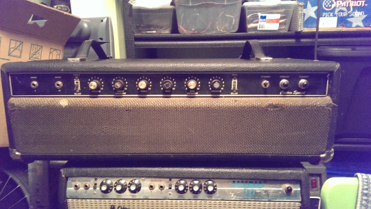
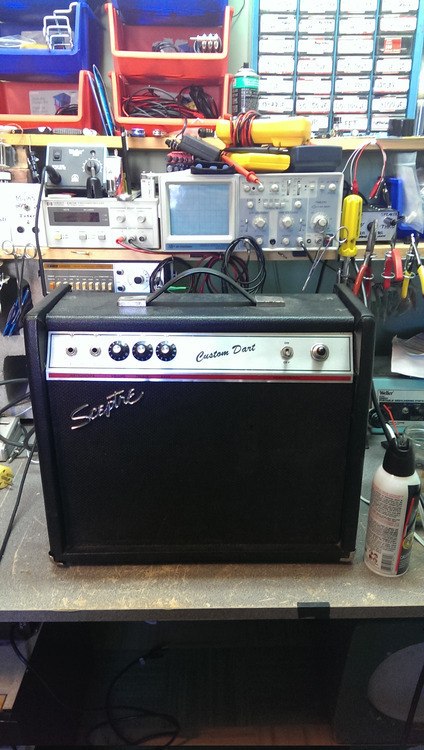
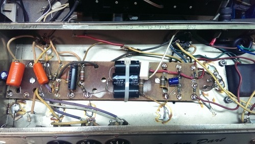
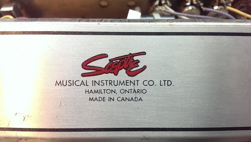
A Canadian Made Scepter "Custom Dart" Champ Clone
The two big names in amps in Canada are Traynor and Garnet, and I see my fair share of them here at the shop (and own a few myself). However, there are a plethora of "no name" amps, usually known as "stencil" amps, that were built by a handful of factories sprinkled around the country, but sold under a dozen or more brand names. These include Pepco, Pine, Russel, Vagabond... and some have literally no name on them at all.
Today's treat is a little Fender Champ clone made under the name Scepter, and built in Hamilton Ontario. Not much if any information is out there on the web about these, and this is the first of it's kind that I've seen with my own eyes.
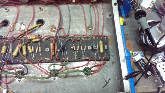
This little fella came in with an intermittent cutout/sudden death problem. It had an old 2-prong cord, and the mains leads were connected to a swiveling, wobbling little terminal strip that could make contact with the chassis if it felt like it. Scary!
I replaced the 2-prong cord with a 3-prong'er, soldering the ground lead to chassis, and put the hot line on a spade, to fit the retrofitted fuse holder. Nice and snug. Some tape under the pilot light should ensure even under twisting, the heaters don't hit the chassis.
Aside from a little bit of 120hz hum, this thing is good to go again. Sounds very nice. The cheap little speaker has a surprisingly clear and musical low end, and the high end is bright yet warm, and not fizzy. A surprisingly good sounding little unit!
Taking a hint from Traynors in the 70's, they have included the brilliant "pop top" design, allowing super easy and convenient access to all the components.
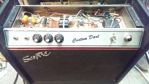
Someone had done a cap job within the last 10 years or so, also replacing some of the old oil caps with Orange Drops, and the grid stoppers from the input jack to the preamp with carbon film half-watters.
Why doesn't anyone make a claim like this anymore?

3 notes
·
View notes
Text
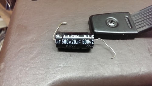
A "fake" electrolytic!
I’ve heard stories over the years of “fake” axial electrolytic caps being sold on eBay, or even reputable places like Ted Weber Speakers. They can usually be spotted by a double crimp, and or rubber plugs on both sides, rather than the negative side being metal.
Well, I finally spotted one myself in a locally made hand-wired Fender Champ clone I had in just for a general once-over.
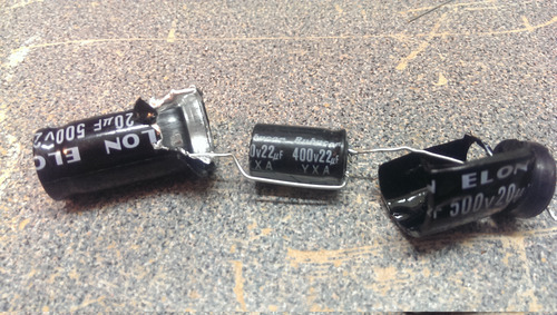
The cap was branded ELON - 20uf @ 500VDC, was crimped on both the plus and minus ends, and had a rubber stopper on both ends.
In the amp, it was is in parallel with an old 40uf 450VDC can cap section.
Also, it wasn't actually soldered down! The lead was just wrapped around a few times. Ohhhh dear.
I decided to risk paying to replace the part myself for the chance to cut open that ELON. Well, I was vindicated.
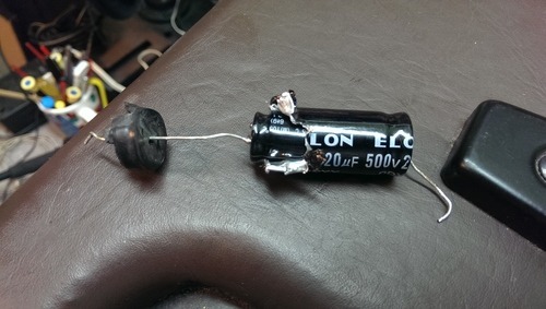
Like a Russian doll, there was an itty bitty little radial leaded cap inside, with an extension leg soldered on, and wrapped up under the shrink wrap! The little tiny cap was marked "20uf 500V". I'll say.
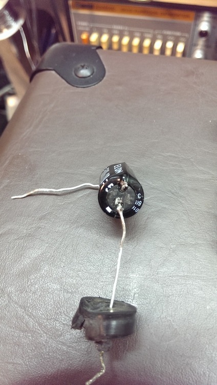
Word on the street is, that these caps are salvaged from disposable cameras, then they have the new leads soldered on with a new wrap, that falsely identifies them as a different rating, then they're stuffed into the axial body. Seems like a lot of effort to me...

I'm guessing if this thing actually had 500V on it, it would curl up and smoke just like the Wicked Witch of the West.
I should note that I measured the cap with my Fluke 115 capacitance metre, and it measured at exactly 21uf. Not so bad!
Peeling the onion back one more layer reveals the TRUE cap inside: a radial Rubycon 22uf @ 400V!
#amps#amp repair#tube amps#fake capacitor#electrolytic fraud#test bench#in the shop#fender champ clone#ELON#Ted Weber caps
5 notes
·
View notes
Text
1952-3 Gates "Biamote" M-5136 Mic Mixer/Preamp
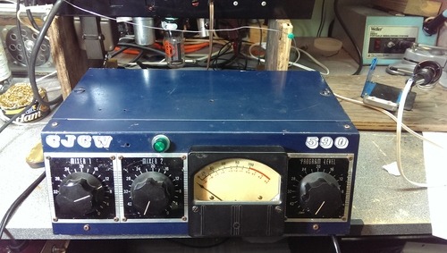
Well, here's a dusty ol' gem I've had sitting on a shelf for 5 years. Inspired by boredom the other day, I hauled it down and started about cleaning it up, and having a look to see if it would turn on without letting the smoke escape.
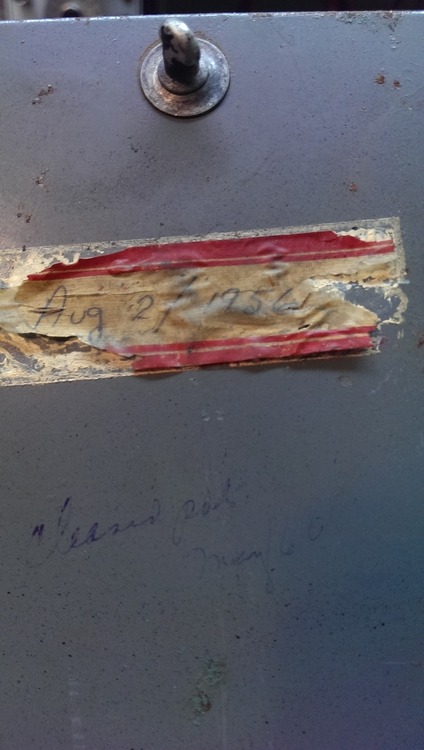
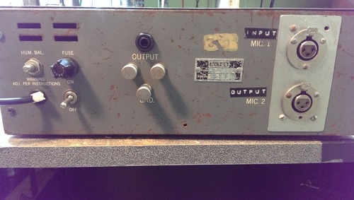
This thing dates from either 1952 or 3, and has a worn and crumbling label on the inside of the lid stating a repair date of "Aug 2 1956". Amazing. The only other record of service is "Cleaned pots, May 1960". Some serious work had been done to it though. A 125V mains indicator lamp had been added to the front panel, whatever the original mic sockets were had been removed and replaced with a hunk of sheet aluminium sporting two Canon brand XLR connectors - one for each of the two mic inputs. The mains power cable had been replaced with a 2-prong cable with a Sony embossed molded end. The grounding scheme had been extensively modified, including putting crimped connectors between the chassis front and back, the panel metre, the PS/Circuit, and pin 1 on the XLR connectors.
I brushed and blew most of the cobwebs and dust off and gave it a wipe down. Then, I removed the 2-prong mains cable, and replaced with a 3-prong, adding the power ground to the main chassis node on the back.
There was one yucky looking electrolytic cap on the board, and I replaced that. In addition, there are two 2 section cans, and one 3 section can. I will replace them later.
The tube compliment is 3x5879 9-pin pentodes, and one 12AX7A. Also a 6X4 tube rectifier.
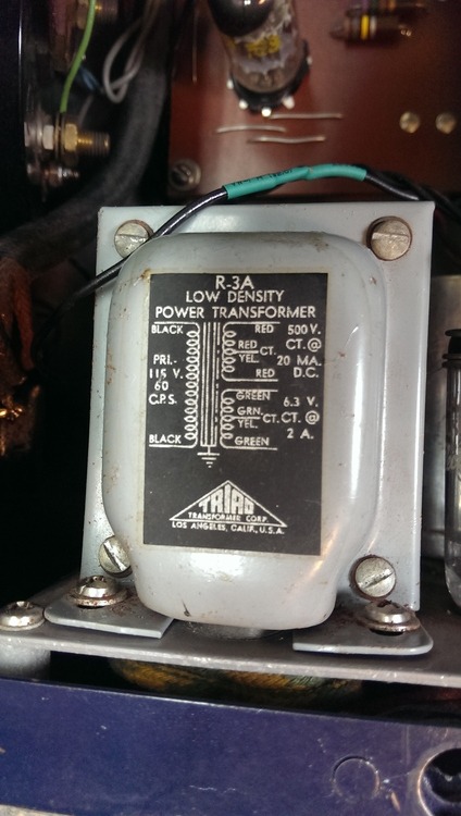
Note the big honkin' output transformer, and the can input transformer! Those two big can looking things on the top right are stepped pots! Insane things. They sure were dirty contacts. I went through about 10 q-tips before they were clean.
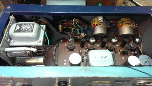
I LOVE seeing things with all their important details right one them. So wonderful!
I then decided that since I will NEVER use this as a mixer, that I'd disable the 2nd mic input, and use the jack as an output. I also replaced the unbalanced 1/4inch output jack with a balanced Cliff jack. I just got me one of those old-school Dyno labelers, and naturally had to label the input and output jacks with it!
I held my breath and fired it up. It came up without any smoke. Signal looks lovely and clean. And holy-tits-piles of gain - about 70-90db by my rough estimation. The metre isn't calibrated, as it was pegging out with TONS more clean headroom available. One day, I'll figure out how and where to adjust the calibration for the metre. Also, I need to replace those can caps. I think they're original. That's insane. 60 years old and still quiet...
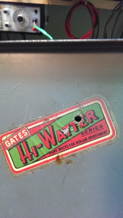
Some advertising inside the lid. I wonder just how much this thing cost in its heyday...
The only two service tags.
Well, now to try it out on a recording I guess, then do the recap and try it again. I guess these things sound incredible. Warm and coloured and very nice. I can't wait!
#gates#biamote#M-5136#preamp#pro audio#recording#recording equipment#repair#vintage#vintage audio#1950s
5 notes
·
View notes
Text
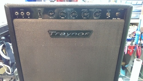
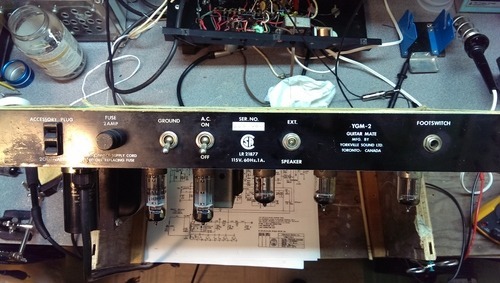
Traynor YGM-2 (Yes, a YGM-2!!)
One of the slightly more rare of the late 60's Traynor combos is the short lived YGM-2 Guitar Mate. This is similar to a YGM-3, but with Trem and NO reverb. Odd. It has the same power section, and very similar bias/preamp/phase inverter arrangement. It also was loaded with a single 12 (originally a Marsland, but long replaced with the 12 out of an Ampeg Jet, I'm told).
The amp came in with some bad history. It had had several trips into another reputable shop, yet always came out "sounding like total garbage". I wondered what could be so wrong that wasn't spotted. Sometimes that just happens, especially if you've stared at it for so long. Can't see the forest for the trees as it were, but someone looking over your shoulder can instantly say "ah, look, a bad ground", or whatever. Happens to the best of us.
I plug it in at the shop and after warm up, the first note through the thing literally sounded like distorted, muffled, crunchy garbage. Completely unreasonable. I shut it down, and put it on the bench.
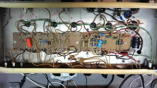
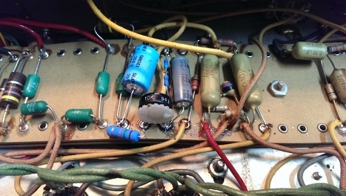
The work done to it was nice. Can cap replacement, and an Orange Drop coupling cap. Several resistors were replaced with very high quality flameproof metal films. All the tubes were brand new. Bias was resistor fixed.
I first went about my usual battery of tests under signal. Wiggle this, tap that. Immediately I got some strange stuff when moving the 1st preamp tube around. HF oscillations, noise, angry waveforms... I immediately cleaned the tube socket and reseated the tube. All the weirdness was gone. Banging and wiggling around wouldn't do diddly. Great! Then, what I had was an EXTREMELY cold bias. Giant crossover notch.
In typical Traynor fashion, the amp circuit was quite different from the one and only published schematic available online. The schematic showed the tubes as being cathode biased, but the amp had a bias tap and supply. It was pretty typical, with the caps replaced the way I like to do it: a 10u @ 100V as the primary, and a 100u @ 100V as the reserve. Since this thing has a bias wiggle trem (the best sounding, IMHO), the bias supply goes right to the trem pot, and gets wiggled by the trem oscillator. Since the pot could fail open, there is a failsafe 1M resistor from the raw side of the bias supply directly to the bias feeder resistors. Opps! There was a mistake in the wiring here, and the raw side of the bias BEFORE the 1M was connected, thus dumping the full RAW bias voltage on the tubes. Move the wire, and add a trim pot for adjustment, and whamo! The thing biases up nice and clean. Doing around 22 watts clean as a whistle!
Opps! I ran out of 20K resistors doing the YRM-1, and had to series connect two 10Ks.
Now that the amp is working wonderfully on the bench, I tried it out with my test speaker. Sounded like a dream. Exactly like they always do. Beautiful fat and sparkling clean, and creamy overdrive when pegged.
I put it back in its home and connected it to its Ampeg speaker, and tried that. Sounded like crap run over twice. The speaker is totally toast. How was that missed? It's beyond me.
The owner has a new driver on order, and will install it himself when it arrives. He's also going to fully seal up the back which sounds simply kick-ass on these units.
#amps#Amp Repair#amp mods#traynor#YGM-2#YGM#YGM-3#Guitar Mate#made in canada#guitar#repairs#music#Music Equipment
4 notes
·
View notes
Text
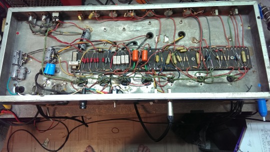
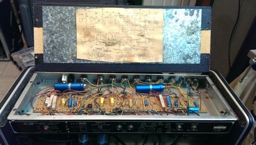
A 1976-79 Traynor YRM-1 Comes to Visit
A very good friend and bandmate of mine scored yet another insane Kijiji deal. This time it was a 1976-79 Traynor YRM-1 Reverb Master 45 Watt head and a closed back Yorkville horizontal 2x12 for around $300. Sickening. Anyway, the head was bone stock, and needed the obvious work done to it, so he sent it to me. We plugged it in at our practice space, and hearing the brutal 60hz hum pump through with the volume all the way off, I recommended it not be powered until the filter caps were replaced. Good thing too.
The tubes were old, but not original. The two power tubes were mismatched 6CA7's. One a "Made in Japan" Sylvania labeled 6CA7 EL34, and the other a "Made in USA" Westinghouse 6CA7.
As you can see, all original 1970's Made in Canada Mallory can caps. The schematic is included on the lid. It has blotchy stains on it from when the filter caps spewed their guts all over the place. Shame, too, as this particular schematic (while barely representing the actual circuit in the amp), is not found online. I might yet try to digitize it and clean it up in Photoshop. This schematic is labeled "YRM-1 YRM-1SC + Eng", meaning the YRM-1 head, the YRM-1SC (4x10 Combo version) and the English export version, with 220V mains.
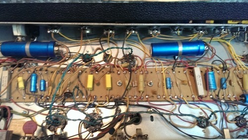
The guts feature the typical Traynor hodgepodge of cloth wire and various plastic covered wire, "mustard" caps, and those yellow brick things. Not a single carbon comp resistor in this guy though! Nice.
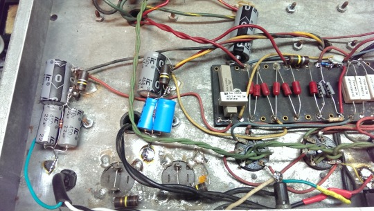
Oh, that cap sure doesn't look good...
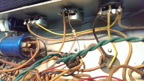
Hmmmm, wonder where all that 60hz hum was coming from...
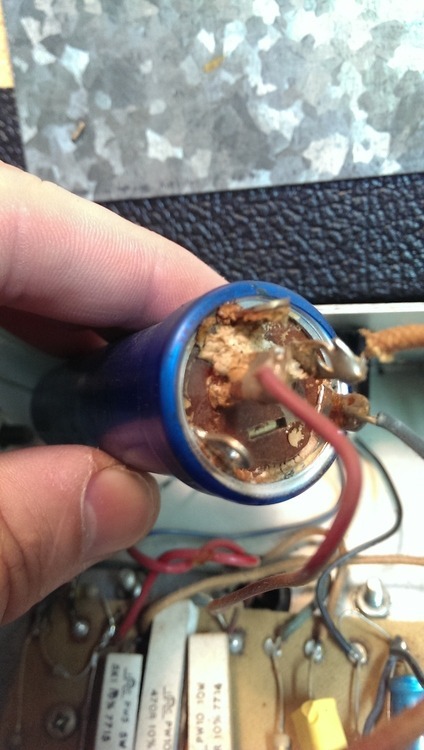
So a full cap job was done, naturally. All discreet capacitors replacing the cans. It really, really isn't worth shelling out the Big Bucks for can replacements, especially when they're hidden away inside anyhow.
Then I had to rewire the mains supply, removing the evil ground switch on the back. Unlike a typical Fender amp, this ground switch had 3 positions: Ground, Ground and Lift. One was normal chassis ground, the other was ground through a 12 ohm resistor and an .047 death cap, and the lift was literally a lift of the chassis ground! Yikes! Also, it was wired so the fuse was on the hot side and the switch was on neutral. Both are now on the hot side.
After the mains were sorted, I modified the bias supply. I put smaller filter caps in. The amp had 68u @ 68V (labeled on the schematic as something different naturally...). Since the bias voltage is supplied right off the mains rectifier bridge, this means if the standby is off, so is the bias voltage. If the bias supply filter is larger than the mains supply, (which it was by 28u as the main filtering was 40u), the plate voltage could come up faster than the bias, and that would not be at all okay for the tubes.
I upped the screen supply filter to 50u, and knocked the rest down to 22, and left the 10s as they were. Then, the bias supply was changed to 2x 10u, so as to allow the bias to come up first. I then converted to a variable bias, by changing the main 27k resistor to a 20K, and adding a 10K pot. This gave enough wiggle room. Interestingly, I originally thought the circuit already had a bias trimmer, as there was a trimmer right in the bias supply area, however, what it is is a 2M trimmer to set the maximum intensity for the trem! Neat!
Unfortunately, after biasing up, and running the thing for a few minutes, one of the mismatched power tubes arced over. I saw and heard the flash, but the damn thing kept operating! I waited to see what would happen next. Another arc about 30 seconds later, and the signal died. I hit the power. The massive 10 watt screen resistors saved the day. They weren't even warm. Overdesign at it's best. If you've ever had a tube arc over in your Fender amp, and had the 1W screen resistor burn through your tube socket, you'd be well grateful for this big cememt guy.
Just waiting for some new tubes to arrive now, and I'll post the "after" pictures and details when available.
4 notes
·
View notes
Text
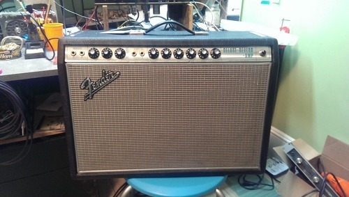
1968 Fender Deluxe Reverb
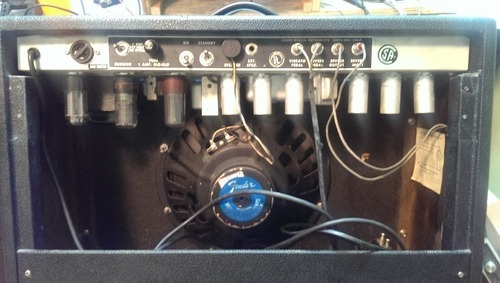
Oh boy, what a treat this was after all those scuzzy '74 Silverfaces I've worked on recently! This is a real-deal 1968 "drip-edge". Cloth covered wiring, CAREFUL lead dress, nice solder joints, (some) better quality components... and the thing was just so CLEAN inside. Unreal. Looks to be almost totally original, save for a mod to the filter caps (which you'll see later).
Note the mis-matched "Made in Canada" tubes - one GE and one Marconi.
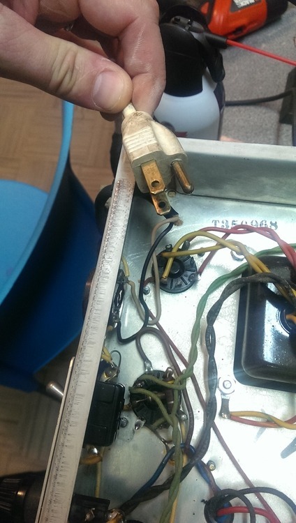
Uhhhhhhhhh oh.... Seeing this usually means...
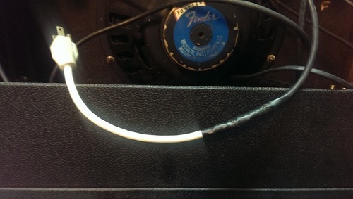
Yep. Some dingbat cut off the original 2-prong connector, and mangled on a 3-prong, with the ground lead disconnected. Why bother? Insanity...
So, not sure if this was an unmarked revision or not, but it looks like aftermarket work to me. Pair of 16u @ 450V's replaced with a single 33u @ 500V. Sure, why not? Notice also the lack of bleeder resistors! Even these 46 year old caps were holding a significant charge after 5 minutes.
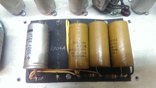
There, that's better. I upped the filtering to 47u. It's fine, trust me. Added some bleeders.
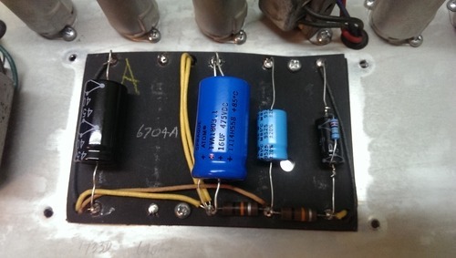
Done up with new caps, and replaced the 47R in the PI with a 100R.

Here's the power all wired up. Proper 3-prong, chassis grounded, HOT side of Mr. Powerline through the fuse then the switch. Note the chassis stamp ending in '68.
When this thing came in, it was doing about 1.25 watts into 8 ohms. When it left, with a new set of NNS (New New Stock) Tung-Sol 6V6GT's, it was cranking out 25.5 Watts, totally clean, into 8 ohms. Not bad at all for a set of $50 tubes in a 22 watt amp!
1 note
·
View note