
Last Seen Blogs

thatscarletflycatcher
Often a thing must be loved before it is lovable

patanu102
Patanu Tumblring

ryu-natsume
Elizabeth

beabaseball
ask me about my cats

t20worldcup20
T20 Worldcup
Photo

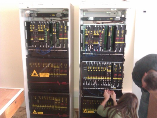
My first DWDM on Flickr.
These blinky lights represent 160Gbps (8x10G across two chassis); soon to be delivering animated GIFs to a browser near you!
26 notes
·
View notes
Text
Small Form Factor Fiber Optic Connectors Tutorial
INTRODUCTION
Conventional duplex Fiber Optic Connectors, such as the SC Duplex defined by the ANSI Fibre Channel Standard, attain the required alignment tolerances by threading each optical fiber via a precision ceramic ferrule. The ferrules come with an outer diameter of two.5 mm, and the resulting fiber-to-fiber spacing (or pitch) of a duplex connector is approximately 12.5 mm. Since the outer diameter of the optical fiber is only 125 μm, it ought to be possible to design a significantly smaller optical connector. Smaller connectors with fewer precision parts could dramatically reduce manufacturing costs and also have the potential to open up new applications for example fiber towards the desktop. Smaller connectors and transceivers would also permit more ports to become added to enterprise servers, fiber optic switches, and communications equipment without increasing the size and cost of these devices. Recently, a brand new class of Small Form Factor (SFF) fiber optic connectors happen to be introduced with the goal of lowering the size of a fiber optic connector to one-half that of an SC Duplex connector while maintaining or reducing the cost, namely, the LC, MT-RJ, SC-DC, and VF-45.
Various kinds of next-generation SFF optical interfaces happen to be proposed towards the Electronics Industry Association/Telecommunications Industry Association (EIMTIA), for inclusion in developing standards such as the Commercial Cabling Standard TIA-568-B. These connectors are described by a reference document called a Fiber Optic Connector Intermateability Standard (FOCIS), which defines the connector geometry so that the same connector build by different manufacturers is going to be mechanically compatible. The EIA/TIA also requires connectors to satisfy some minimal performance levels, separate from connector design; test methodologies are based on the EIA/TIA Fiber Optic Test Procedures (FOTPs). Other industry specifications will also be relevant to these connectors; for example, Bellcore spec. GR-326-CORE defines fiber protrusion from a ferrule to ensure physical contact and also to prevent back-reflections in the connector. The appropriate FOCIS documents defined for connectors that have currently been proposed to the TIA are given within the table below.
Note: the authoring company listed does not necessarily support or manufacture just one connector type, nor performs this table include all the supporters or manufacturers of each connector type.
MT-RJ SFF FIBER OPTIC CONNECTOR
The MT-RJ Connector utilizes the same rectangular plastic ferrule technology as the Multi-fiber Termination Push-on (MTP) array style connector first produced by NTT Corporation, with a single ferrule body housing two fibers at a 750-μm pitch as in the figure below. These ferrules are available in both single-mode and multimode tolerances, with the lower cost multimode version typically comprised of a glass-filled thermoplastic and also the critically tolerance single-mode version comprised of a glass-filled thermoset material. Unlike the thermoplastic multimode ferrules, which can be manufactured using the standard injection mold process, the thermoset single-mode ferrules should be transfer molded, which is generally a slower but more accurate process.
By design, the alignment of two MT-RJ ferrules is achieved by mating a pair of metal guide pins with a corresponding pair of holes within the receptacle (shown within the figure below). This feature makes the MT-RJ the only real small form factor connector having a distinct men and women connector. As a general rule, wall outlets, transceivers, and internal patch panel connectors will retain the guide pins, thus making their gender male, and also the interconnecting jumpers will have no pins (female). In the event that the two jumper assemblies require mating mid-span, a unique cable assembly with one male end and something female end must be used. However, some unique designs do permit the insertion and extraction of guide pins within the field, affording the consumer the ability to alter the connector's gender as needed.
Latching of the MT-RJ connector is modeled following the copper RJ-45 connector, whereby just one latch arm positioned at the top of the connector housing is positively latched in to the coupler or transceiver window. Even though this latch design is similar in all the MT-RJ connector designs, individual latch pull strengths may vary depending on the connector material, arm deflection, and the relief angles included in the mating receptacles. Because of this it is recommended that connector pull strengths be evaluated as a complete interface; with respect to the specific manufacturer's connector, coupler, or transceiver design, the coupling performances can vary.
MT-RJ connectors are usually assembled on 2.8-mm round jacketed cable housing two optical fibers in one of three internal configurations. The very first construction style consists of the two optical fibers encapsulated within a ribbon at a 750-μm pitch. This method is unique towards the MT-RJ connector and it is designed specifically to complement the fibers spacing to the pitch from the ferrule for easy fiber insertion. Even though this construction style may be ideal for a MT-RJ termination, it will present some difficulty when manufacturing a hybrid assembly and availability may also be an issue according to its uniqueness. Another design, which is more universal, relies on a single 900-μm buffer to house two 250-μm fibers. This construction is much more conducive to hybrid cable manufacturing, however the fibers will naturally maintain a 250-μm pitch, thus making fiber insertion rather difficult.
The third design is considered a standard construction and it is used across the industry. In this configuration each individual fiber is buffered having a PVC coating. The coating thickness is typically 900 μm, but as in the previous case this does cause a mismatch from the fiber to ferrule pitch. To pay for this, some connector designs add a fiber transition boot, which gradually reduces the fiber pitch to 750 μm, while others simply use a nonstandard buffer coating of 750 μm.
In general, the assembly and polish of the MT-RJ factory style connector is significantly more difficult compared to other small form factor connectors. Typical MT-RJ designs possess a minimum of eight individual components that must definitely be assembled after the ferrule has been polished, allowing for a number of handling concerns. Just like the case of most MT-style ferrules, the perpendicularity or flatness from the ferrule end face with regards to the ferrule's inner shoulder is crucial, and this can't be accomplished if the connector is preassembled. Another unique requirement of the MT-RJ polish involves fiber protrusion. The ferrule end face is regarded as flat, but with respect to the polishing equipment, fixtures, as well as contamination, some angularity can happen. Therefore, it is recommended that the fibers themselves protrude 1.2 to 3.0 μm in the ferrule surface to assure fiber-to-fiber contact.
SC-DC SFF FIBER OPTIC CONNECTOR
The SC-DC (Dual Contact) or SC-QC (Quattro Contact), developed by Siecor and illustrated in the figure below, includes a connector body design resembling a SC simplex connector with a round thermoset-molded ferrule able to handle either two or four optical fibers, as with the figure. The connector is designed to support both single-mode and multimode cabling applications. However, the SC-DC is among the few connectors which is used exclusively for cable interconnecting and therefore has no transceiver support.
As when it comes to the MT-RJ connector, the SC-DC fibers take presctiption a 750-μm pitch, as the SC-QC fibers take presctiption a 250-μm pitch. Exactly the same ferrule and housings are used in both connectors, so the only feature that distinguishes between the two is simply the number of fibers used. The 4 ferrule holes of around 125-μm diameter are placed on 250-μm centers across the ferrule centerline to form a SC-QC connector. By utilizing only the two outermost ferrule holes and leaving the inner two empty, the SC-DC is made.
Although the ferrule composition is extremely similar to that used over the MT technologies, the geometry and alignment methods are very different. The SC-DC ferrule includes a standard round shape having a 2.5-mm diameter, but unlike its ceramic counterparts, there's two semicircular groves with a 350-μm radius positioned along both sides of the ferrule at a 180 degree centigrade interval. This selection provides the ferrule- to-ferrule alignment when mated using the corresponding ribs from the coupler. The design of this feature within the couplers differs for a single-mode and multi- mode connection. The multimode coupler utilizes a one-piece, all composite alignment insert with molded fibs, as the single-mode coupler incorporates two precision alignment pins captured inside the sleeve. By design, the ribs from the coupler and grooves in the ferrule are on exactly the same 2.6-mm pitch as the pins of a male MT-RJ connector to allow for possible hybrid mating of these two connector types.
The latching mechanism of the SC-DC connector uses the same push-pull style used on the industry standard SC simplex connector, and also the outer housing dimensions are identical. Since the two connectors appear exactly the same physically but are not functionally interchangeable, the housing alignment key from the SC-DC is offset to help distinguish between the 2 connector types and stop any confusion within the field. By following the same basic footprint as the SC connector, this new SFF optical connector already has a familiar feel and look with proven plug reliability.
SC-DC connectors and cable assemblies are manufactured and sold solely by Corning; therefore, the variability of design and cable material is not an issue as is the case along with other SFF connectors. The connectors are typically assembled onto 2.8-mm round jacketed fiber incorporating a single-ribbon fiber populated with either 2 or 4 fibers, which assists in the alignment of the fiber to the ferrule holes. The internal ferrule geometry can accommodate the standard single-fiber cables, and this may be a choice for the fabrication of hybrid cable assembles.
As previously stated, the size and form of the SC-DC ferrule is comparable to the standard ceramic and for that reason can be polished in much the same manner and still produce endface geometries similar to the MT-RJ. A fiat endface polish may be the desired result, much as it is with the MT-style ferrules. However, the perpendicularity is referenced towards the sides from the ferrule rather than to an internal feature. Therefore, the SC-DC connector could be preassembled and polished like a complete connector. The ability to preassemble a connector significantly reduces the complexity of producing and typically results in a low rework rate.
The SC-DC connector is available in a field-installable version, the SC-DC UniCam, which utilizes pre-polished fiber stubs much like other SFF solutions. Alignment of the fiber stubs to the in-field cleaved fiber is achieved through a gel-filled mechanical splice element. The splice element is closed and opened with a mechanical cam and is retained inside a connector housing. Termination of the standard SC-DC connector may also be accomplished in the field by using conventional equipment and techniques much like the field termination of a SC-style connector.
VF-45 SFF FIBER OPTIC CONNECTOR
The VF-45 connector, developed by 3M and shown in the figure below, is probably the most innovative SFF connector design for the reason that it eliminates the requirement for precision ferrules and sleeves altogether. The general look and feel from the "plug-to socket" design closely resembles the conventional telephony RJ-45 "connector-to-jack" system whereby the cable assembly mates directly to a terminated socket, therefore reducing the need for couplers. Even though this concept has been around for years within the cooper industry, the development of a bare fiber optic interface, using alignment grooves with no index matching gels, requires some revolutionary techniques.
The VF-45 connector incorporates two 125-μm optical fibers, suspended in free space, on a 4.5-mm pitch and guarded by a RJ-45 style housing with a retractable front door designed to protect the fibers. The connector design supports both single-mode and multimode tolerances by counting on the inherent precision from the optical fibers inside the two injected molded v-grooves of either the transceiver or perhaps a VF-45 socket. The design of the interconnect allows the natural spring forces from the optical fibers to align the fibers within the v-grooves as well as ensuring physical fiber-to-fiber contact.
Because of the uniqueness of this interconnect, the geometry of the endface polish of both plug and receptacle fibers have been modified to supply optimum performance. The VF-45 optical connection relies on the spring force created by the bowing of the optical fibers to provide a physical contact force of approximately 0.1 N. This force, along with an 8-degree angle polished endfaces, creates the optimum connection and return loss results. The tips of the plug fibers will also be beveled at 35 degrees, allowing a 90-μm contact area and providing a relief for the fiber to slip into the v-grooves with no damage to to the core region. This chamfer is not needed on the receptacle fibers since they remain stationary as the plug fibers might have to endure multiple insertions.
As previously mentioned, the contact force created in the optical interface directly influences the optical performance from the plug-socket connection. This downward compressive force is generated once the two fibers of the plug engage with the resident fibers from the socket and cause a slight "bow" within the plug fibers. Because of the constant force on these fibers, long-term reliability on standard optical fibers was a concern, and therefore a specialized high-strength optical fiber was developed for this application, called GGP (Glass-Glass-Polymer) fiber. GGP fiber consists of 100-μm glass fiber having a polymeric coating put on bring the outer diameter to 125 μm. By reduction of the outer diameter from the glass, the tensile stress on the fiber is minimized and the additional coating offers protection against abrasions from the v-grooves and cuts down on the chance of damage to the glass throughout the mechanical stripping process utilized in the termination process.
The factory termination of the VF-45 jumper plugs is considerably not the same as the conventional ferrule-based connectors. The process of threading a 125-μm fiber right into a precision ferrule hole filled with epoxy has become eliminated and replaced with a mechanical fiber holder that grips the fibers in position. The fibers will be cleaved and polished towards the endface geometry previously described, and the cable strain relief is slid into place. The fibers and holder are then placed in a safety shroud, and the front door cover is installed. The relative simplicity of this manufacturing process makes the VF-45 connector among the best candidates for any fully automated production line.
The socket from the VF-45 was created specifically for termination within the field with minimal effort and training. After preparing the fibers for termination by removing outer buffer material, they are inserted into a mechanical fiber holder that retains the fiber by gripping them in the deformable aluminum crimp. The fibers will be cleaved and hand polished to an 8-degree angle, having a slight radius generated by the durameter of the polishing pad. The fiber holder with the polished fibers is guided to the socket v-grooves, and the housing plate is snapped into position. Although this approach to field termination does vary from the other pre-polished SFF connectors, the total termination some time and the complexity from the process are extremely similar.
LC SFF FIBER OPTIC CONNECTOR
The LC Connector produced by Lucent Technologies and shown below is a more evolutionary method of achieving the goals of the SFF connector. The LC connector utilizes the traditional components of a SC duplex connector having independent ceramic ferrules and housings, using the overall size scaled down by one-half. The LC family of connectors includes a stand-alone simplex design; a "Behind The Wall" (BTW) connector and also the duplex connector obtainable in both single-mode and multimode tolerances are designed using the RJ-style latch.
The outward appearance and physical size of the LC connector varies slightly depending on the application and vendor preference. Although all the connectors within the LC family have similar latch styles modeled following the copper RJ latch, the simplex version of the connector includes a slightly longer body than either the duplex or BTW version, and also the latch comes with an additional latch actuator arm that's designed to assist in plugging too to prevent snagging within the field. The BTW connector may be the smallest from the LC family and it is designed like a field- or board-mountable connector using 900-μm buffered fiber and in some cases has a slightly extended latch for extraction purposes. The duplex form of this connector has a modified body to simply accept the duplexing clip that joins the 2 connector bodies together and actuates the two latches as one. Finally, even the duplex clip itself has variations with respect to the vendor. In some cases the duplex clip is a solid one-piece design and must be placed around the cable prior to connectorization, while other designs have slots included in each side to permit the clip to be installed after connectorization. To conclude, all LC connectors are not created equal, and based on style and manufacturer's preference, there may be attributes which make one connector more suitable for a specific application then another.
The LC duplex connector incorporates two round ceramic ferrules with outer diameters of 1.25 mm along with a duplex pitch of 6.25 mm. These ferrules are aligned with the traditional couplers and bores using precision ceramic split or solid sleeves. So that they can improve the optical performance to higher than 0.10db at these interfaces, the majority of the ferrule and backbone assemblies are made to allow the cable manufacturer to tune them. Tuning from the LC connector simply consists of rotating the ferrule to one of four available positions dictated through the backbone design. The idea is basically to align the concentricity offset of each ferrule to a single quadrant at 12:00; essentially, if all the cores are slightly offset within the same direction, the prospect of a core-to-core alignment is increased and optimum performance is possible. Although this concept has its own merits, it's yet another costly step in the manufacturing process, and in the case where a tuned connector is mated by having an untuned connector, the rise in performance may not be realized.
Typically, the LC duplex connectors are terminated onto a new reduced-size zipcord referred to as mini-zip. However, because the product matures and also the applications expand, it may be found on a number of different cordages. The mini-zip cord is among the smallest in the industry with an outer diameter of 1.6mm compared with the conventional zipcord for an SC style product of 3.0 mm. Even though this cable has transpired industry standard testing, the cable manufacturers have raised some issues in regards to the ability of the 900-μm fibers to maneuver freely inside a 1.6-mm jacket and others involving the overall crimped pull strengths. Therefore, some end users and cable manufactures are opting for a larger 2.0-mm, 2.4-mm, or perhaps the standard 3.0-mm zipcord. In applications in which the fiber is either protected inside a wall outlet or cabinet, the BTW connector can be used and terminated directly onto the 900-μm buffers with no jacket protection.
The factory termination of the LC cable assemblies is very similar to other ceramic-based ferrules while using standard pot and polish processes with a few minor differences. The one-piece design of the connector minimizes production handling and helps to increase process yields when compared with other SFF and standard connector types. Due to the smaller diameter ferrule, the polishing times for an LC ferrule may be slightly lower than the standard 2.5-mm connectors, however the real production advantage is realized in the increased number of connectors that can be polished at one time in a mass polisher. For the reasons mentioned previously and because the process is familiar to most manufacturers, the LC connector may be considered one of the easiest SFF connectors to factory terminate.
Field termination from the LC connector has typically been accomplished through the standard pot and polish techniques using the BTW connector. However, a pre-polished, crimp and cleave connector is also available. The LCQuick Light field-mountable BTW style connector produced by Lucent Technologies is really a one-piece design with a factory polished ferrule as well as an internal cleaved fiber stub. Unlike other pre-polished SFF connectors previously discussed, the LCQuick light secures the inserted field cleaved fiber to some factory polished stub by crimping or collapsing the metallic entry tube onto the buffered portion. This is achieved by using a special crimp tool that's designed not to damage the fibers. However, this means the installer has but one chance for a great connection. The LCQuick light was created specifically for use within protected environments such as cabinets and wall outlets and it has no provision for outer jacket or Kevlar protection.
OTHER TYPES OF SFF FIBER OPTIC CONNECTORS
Fiber-Jack Connector
The Fiber-Jack (FJ) may be the non-trademarked name for the Opti-Jack connector developed by Panduit Corporation. As shown in the figure below, this connector incorporates two industry standard SC duplex ceramic ferrules, each 2.5 mm in diameter. However, the spacing between ferrules has been reduced from 1.27 mm (0.5 in.) as with a standard SC Duplex connector to only 0.63 mm (0.25 in.). The ferrules are independently spring loaded and are aligned inside a receptacle by standard split-sleeve mechanical techniques. Although this simplifies the connector design, additionally, it means that the connector must incur the full cost of two ceramic ferrules; how this can eventually match up against other SFF ferrule costs has not yet been determined. The connector latch is modeled after the industry standard RJ-45 wall jack and has found many initial applications in building wiring to wall outlets. The connector will come in both single-mode and multimode versions, which preserve the TIA industry standard color coding on the plug body and the termination cap on the jack.
The FJ connector is also available with color coding to identify different networks, applications, regions of the building, or portions of the cable infrastructure, to facilitate network administration. Following the category 5 wiring conventions, the FJ housing and plugs may be color created in black, blue, gray, orange, red, beige, or white. The FJ was also among the first SFF connectors to be specified by a TIA FOCIS document to be used with plastic optical fiber. Since it employs standard ceramic ferrules, the FJ can hold plastic fiber with an outer diameter up to 1 mm. The FJ supports standard duplex jumper cables, couplers, and adapters, although FJ transceivers are not widely available.
MU Connector
Another type of SFF connector, produced by NTT to serve as both a standard Fiber Optic Patch Cable and an optical backplane interface, is the Multi-termination Unibody or MU Connector. This connector is also available from various sources under slightly different names; for instance, the version manufactured by Sanwa Corporation is called the SMU. As shown within the figure, the fundamental MU connector is really a simplex design measuring 6.6 mm wide and 4.4 mm high, having a center-to-center spacing of four.5 mm in duplex or multifiber applications. It had been standardized by IEC 61754-6, "Interface standards type MU connector family," in 1997; other standards bodies, including JIS and IEEE 1355 Heterogeneous Interconnect (the next bus architecture), have endorsed the MU too. A backplane version of the MU can be obtained, which measures 13 mm wide and 42 mm high. Its small size is achieved by using a ceramic ferrule 1.25 mm in diameter, roughly half how big a standard SC connector ferrule. Consequently, a different type of physical contact polishing was developed to accommodate the smaller ferrules.
Smaller diameter zirconia split-sleeves are also developed to support duplex couplers, adapters, and similar jumper cable applications. A self-retention mechanism is employed, similar in design to a miniature push-pull SC latch. Indeed, the MU may also be referred to as a mini-SC connector due to the similarities in look and feel. This really is consistent with the intended applications, as it permits blind mating of the connector inside a printed circuit board backplane more readily than an RJ-45 style latch.
The MU finds some applications as a front panel patch cable on optical switches or multiplexers which have a large amount of fiber connections; these interfaces are expected to be incorporated into optical backplanes on next-generation equipment. The plug and jack structure of MU connectors can be simply cascaded to produce multifiber parallel interface designs. It has been suggested that future designs using the MU could accommodate hundreds or even thousands of fibers when used in this configuration. Transceivers for the MU interface are not yet accessible, although some development work is under way in this area.
COMPARISON OF SFF FIBER OPTIC CONNECTORS
The table below presents a comparison of the different features of the four major SFF connectors. A brief description of each connector and its alignment method are given, followed by a discussion of the distinguishing characteristics and their impact on the connector and transceiver.
Several different design approaches can be used to reduce the size of a fiber-optic connector. One approach is by using a single ferrule with multiple fibers; this is the concept behind the SC-DC and MT-RJ connectors. The SC-DC (dual connect) and SC-QC (quad connect) make use of a standard SC connector body and latching mechanism with an offset key, but a brand new round plastic ferrule design that includes either two fibers (750-mm pitch) or four fibers (250-mm pitch) in a linear array. Alignment is supplied by semicircular grooves within the sides from the SC-DC ferrule, which mate with corresponding ribs within the receptacle. This connector has been used by IBM Global Services included in the Fiber Quick Connect system; it is currently limited to applications in patch panels and also the cable infrastructure. The most radical, and innovative, method for a smaller connector would be to eliminate ferrules altogether; this is the case for that VF-45 connector. Within this connector, a set of optical fibers are aligned using injection-molded thermoplastic V-grooves; the fibers are cantilevered in free space on a 4.5-mm pitch and are protected by the connector outer body. When connected to a receptacle, the fibers bend slightly to have physical contact; better performance is achieved when utilizing optical fibers which have a special strength coating in addition to the outer jacket.
The MT-RJ connector uses the same rectangular plastic ferrule concept as the multifiber MTP connector, with two fibers on a 750-mm pitch and a latching mechanism in line with the RJ-45 connector. Alignment in this instance is provided with a pair of metal guide pins within the connector, which mate with a corresponding pair of holes in the receptacle. This feature makes the MT-RJ the only real small form factor connector with distinct male and female connector ends. A more evolutionary method of designing SFF connectors involves simply shrinking the conventional SC Duplex connector, maintaining a single fiber in every of the ceramic ferrules, and taking advantage of conventional alignment techniques applied to the ferrules. The LC connector uses this approach and shrinks the ferrules to 1.25 mm across with a fiber pitch of 6.25 mm (duplex). LC is the only small form factor connector which can be either simplex or duplex.
Although many of these designs exhibit comparable performance, some application-specific differences remain, for example axial pull requirements. Some SFF connectors, such as the SC-DC and VF-45 connectors, are made to disengage from their receptacles under an applied pull force above 45 N; this is to prevent damage to the connector and induce a clear optical failure within the link. (It is problematic to identify a link failure when the connector remains engaged but exhibits high optical losses under stress.) Another design approach utilized by LC and MT-RJ is to retain the connector within the receptacle under higher force without excessive optical loss. The magnitude from the pull force is really a requirement that will vary with respect to the application. However, it is essential for all the applications that the cable unplug or mechanically fail before the loss increases.
Reference: Handbook of Fiber Optic Data Communication, Third Edition
0 notes
Text
Passive Optical Network Overview
A Passive Optical Network (PON) is illustrated schematically in the figure below. A feeder fiber in the Central Office (CO) runs to some Remote Node (RN), which houses a passive optical power splitterkombiner. From there, around 32 fibers branch to the subscribers. If these fibers extend up to the homes (H), as shown within the figure, this technique is known as a Fiber-To-The-Home (FTTH) system. Alternatively, when the fibers terminate at the curb, the machine is known as a Fiber-To-The-Curb (FTTC) system. The ultimate distribution from the curb to the homes is accomplished, for example, by twisted-pair copper wires or radio. All systems that bring the fiber relatively near to the subscriber are collectively referred to as FTTx systems.
In a conventional telephony access network, the bond between the CO and the remote node is really a digital, possibly optical line. The ultimate distribution from the remote node to the subscribers, however, is accomplished with analog signals over twisted-pair copper wires. Thus, the remote node must be active; that's, it needs to be powered to perform the conversion from the high-speed digital signal towards the analog signals. In comparison, a PON product is all optical and passive. Just because a PON does not require outside power supplies, it's low in cost, easy to maintain, and reliable.
A PON is really a point-to-multipoint network because the optical medium is shared one of the subscribers. Information transmitted downstream, from the CO to the subscriber, is received by all subscribers, and knowledge transmitted upstream, in the subscribers to the CO, is superimposed at the passive combiner before it is received in the CO. To avoid data collisions in the upstream direction, the subscriber data should be buffered and transmitted in short bursts. The CO must coordinate which subscriber can send a burst at which point in time. This method is known as Time Division Multiple Access (TDMA) and requires burst-mode transmission. The downstream direction is much more straightforward: the CO tags the information with addresses and broadcasts it to any or all subscribers in sequential order. Each subscriber simply selects the information with the appropriate address tag. This method is known as Time Division Multiplexing (TDM), and conventional continuous-mode transmission may be used. Upstream and downstream transmissions usually are separated by utilizing two different wavelengths (WDM bidirectional transmission).
See the attached products in Fiberstore:
FTTH Patch Cables
PON Components
FTTx WDM Filters
The most promising PON systems are as following:
1. BPON (Broadband Passive Optical Network), which cames the data in ATM cells and therefore also is referred to as ATM-PON.
2. EPON (Ethernet Passive Optical Network), which cames the information in Ethernet frames, because the name implies. In general, PON FTTx networks are limited to relatively small distances (up to 20 km) and currently are operated at modest bit rates (50 Mbps to 1.25 Gbps). Inside a typical BPON FTTH scenario, 16 to 32 homes 9 share a little rate of 155 Mbps, giving each subscriber a typical speed of Five to ten Mbps. This is sufficient for fast Internet access, telephone service, and video on demand. Sometimes, an all-optical CATV service is provided within the PON infrastructure using a third wavelength.
Besides the TDM/TDMA approach outlined above, there are several other types of PON systems. For example, the WDM-PON system, in which a different wavelength is owned by each subscriber, continues to be studied extensively. In WDM-PON systems, data collisions are avoided without the need for burst-mode transmission. However, the Optical WDM Components required for such a system currently are too expensive, making WDM-PON uneconomical. For more information on PON systems see Fiberstore PASSIVE OPTICAL NETWORK TUTORIAL.
Article source: http://www.fiberopticshare.com/
0 notes
Text
10 Gigabit Ethernet Standards for Optical Fiber Networking
The throughput potential for optical fiber is extraordinary, and engineers continue to push its limits. In 2002, IEEE published its 802.3ae standard for fiber optic Ethernet networks transmitting data at 10 Gbps. Several variations were explained the standard, but all share some characteristics in keeping.
For example, all of the fiber optic 10-Gigabit options depend on a star topology and allow for only on repeater. (However, optical transceivers, switches, and not repeaters, are more commonly used with high-speed data links.) Additionally, all 10-Gigabit standards operate under full-duplex mode only. The 10-Gigabit fiber optic standards differ significantly within the wavelength of light each uses to issue signals and, as a result, their maximum allowable segment length differs also. You will find mainly three 10 Gigabit Ethernet (10GbE) standards for optical fiber networking: 10GBASE-SR/SW, 10GBASE-LR/LW, and 10GBASE-ER/EW.
10GBASE-SR/SW
The 10-Gigabit options using the shortest segment lengths are 10GBASE-SR/SW. By now you can reckon that the "10G" means the standard's maximum throughput of 10 Gbps and "BASE" means baseband transmission. "S" means short reach. The fact that one of the standards ends with "R" and also the other ends with "W" reflects the type of Physical layer encoding each uses. To put it simply, 10GBASE-SR is designed to use fiber connections on LANs, and 10GBASE-SW is made to work with WAN links that use a highly reliable fiber optic ring technology called SONET.
10GBASE-SR and 10GBASE-SW depend on MMF and transmit signals with wavelength of 850 nm. As with the GE standards, the maximum length on a 10GBASE-SR or 10GBASE-SW nework depends on the diameter from the fibers used. It also depends on the modal bandwidth, the maximum segment lengths is 300 m. If 62.5 μm fiber is used with the maximum possible modal bandwidth, a 10GBASE-SR or 10GBASE-SW segment can be 66 m. Either way, this 10GbE technologies are best suited for connections inside a data canter or building, as its distance is easily the most limited.
Details concerning the 10GBASE-SR standard (WIKIPEDIA):
10GBASE-SR is a port type for MMF and uses 850 nm lasers. Its Physical Coding Sublayer (PCS) 64b/66b is defined in IEEE 802.3 Clause 49 and its Physical Medium Dependent (PMD) in Clause 52. It delivers serialized data in a line rate of 10.3125 Gbps. The 10GBASE-SR transmitter is implemented having a VCSEL which is low cost and low power. 10GBASE-SR delivers the lowest cost, lowest power and smallest form factor optical modules.
Related products in Fiberstore: SFP-10G-SR (Compatible with Cisco equipment)
Tips: For 2011, 10GBASE-SR is projected to create up one fourth of the total 10GbE adapter ports shipped. There is a non-standard lower cost, lower power variant sometimes referred to as 10GBASE-SRL (10GBASE-SR lite). This really is interoperable with 10GBASE-SR only has a reach of 100 m.
10GBASE-LR/LW
Another standard defined in IEEE 802.3ae is 10GBASE-LR/LW, where the "L" stands for long reach and also the other pasts stand for the same meaning as 10GBASE-SR/SW. 10GBASE-LR/LW networks carry signals with wavelengths of 1310 nm through SMF. Their maximum segment length is 10 km. Out of the box the case using the previously described 10GbE standard, in 10GBASE-LW the "W" reflects its unique method of encoding that allows it to work over SONET WAN links. 10GBASE-LR/LW technology is suited to WAN or MAN implementations.
Details concerning the 10GBASE-LR standard (WIKIPEDIA):
10GBASE-LR is a port type for SMF and uses 1310 nm lasers. Its PCS 64b/66b is determined in IEEE 802.3 Clause 49 and its PMD in Clause 52. It delivers serialized data in a line rate of 10.3125 Gbps. The 10GBASE-LR transmitter is implemented having a Fabry rot or Distributed feedback laser (DFB). DFB lasers are more expensive than VCSELs however their high power and longer wavelength allow efficient coupling in to the small core of SMF over greater distances. 10GBASE-LR has a specified reach of 10 km, but 10GBASE-LR optical modules can frequently manage distances of up to 25 km without any data loss.
Related products in Fiberstore: SFP-10G-LR (Compatible with Cisco equipment)
10GBASE-ER/EW
For the longest fiber optic segments, network administrators choose 10GBASE-ER/EW. Within this standard, "E" stands for extended reach. 10GBASE-ER and 10GBASE-EW require SMF, through which they transmit signals with wavelengths of 1550 nm. These standards allow for segments as much as 40 km. The 10GBASE-EW standard specifies encoding that makes it compatible with the SONET transmission format. Given their long-distanc capabilities, 10GBASE-ER/EW standards are best suited for use on WANs.
Details about the 10GBASE-ER standard (WIKIPEDIA):
10GBASE-ER is a port type for SMF and uses 1550 nm lasers. Its PCS 64b/66b is determined in IEEE 802.3 Clause 49 and it is PMD in Clause 52. It delivers serialized data at a line rate of 10.3125 Gbps. 10GBASE-ER includes a reach of 40 km over engineered links and 30 km over standard links. The 10GBASE-ER transmitter is implemented by having an externally modulated laser (EML).
Related products in Fiberstore: SFP-10G-ER (Compatible with Cisco equipment)
NSPs and ISPs use 10GbE where visitors are aggregated and customers demand fast data transfer. As with any new technology, however, when 10GbE becomes more economical, more organizations will adopt it for his or her WANs and LANs. Even faster Ethernet networks are on the way, like the 40G and 100G Ethernet.
Reference: Fiberstore
0 notes
Text
Ethernet Standards for Optical Fiber Networking
There are mainly three standards for optical fiber networking: 100BASE-FX, 1000BASE-LX, and 1000BASE-SX.
100BASE-FX
100BASE-FX is a version of Fast Ethernet over optical fiber. It uses a 1300 nm near-infrared (NIR) light wavelength transmitted via two strands of optical fiber, one for receive(RX) and the other for transmit(TX). Maximum length is 412 m (1350 feet) for half-duplex connections (to make sure collisions are detected), and 2 km (6600 feet) for full-duplex over multimode fiber (MMF). 100BASE-FX uses the same 4B5B encoding and NRZI line code that 100BASE-TX does. 100BASE-FX should use SC, ST, LC, MTRJ or MIC connectors with SC being the preferred option.
100BASE-FX is not compatible with 10BASE-FL, the 10-Mbps version over optical fiber. The 100BASE-FX standard specifies a network capable of 100-Mbps throughput that uses baseband transmission and fiber optic cabling. 100BASE-FX requires MMF containing at least two strands of fiber. In half-duplex mode, one strand is used for data transmission while the other strand can be used for reception. In full-duplex implementations, both strands are used for sending and receiving data. The standard allows for a maximum of one repeater for connecting segments. 100BASE-FX uses a star topology using its repeaters connected inside a bus fashion.
100BASE-FX, like 100BASE-T, can also be considered Fast Ethernet and it is described in IEEE's 802.3u standard. Organizations switching, or migrating, from UTP to fiber media can combine 100BASE-TX and 100BASE-FX within one network. To get this done, transceivers in computers and connectivity devices should have both RJ-45 and SC, ST, LC, or MT-RJ ports. Alternatively, a 100BASE-TX to 100BASE-FX media converter can be utilized at any point in the network to interconnect the different media and convert the signals of one standard to signals that actually work the other standard.
Related products in Fiberstore: Fast Ethernet Media Converter
1000BASE-LX
IEEE has specified three different types of 1000BASE, or 1-Gigabit, Ethernet technologies to be used over optical fiber in its 802.3z standard. 1000BASE-LX is a fiber optic gigabit Ethernet standard specified in IEEE 802.3 Clause 38 which utilizes a long wavelength laser (1270 to 1355 nm), along with a maximum RMS spectral width of 4 nm. It is specified to operate over a distance as high as 5 km over 10 |¨?m single-mode fiber (SMF).
1000BASE-LX may also run over all common types of MMF with a maximum segment length of 550 m. For link distances greater than 300 m, the use of a special launch conditioning patch cord are usually necesary. This launches the laser in a precise offset from the center of the fiber which causes it to spread over the diameter from the fiber core, reducing the effect known as differential mode delay which occurs when the laser couples onto merely a small number of available modes in MMF.
Probably the most common 1-Gigabit Ethernet (GE) standard being used today is 1000BASE-LX. The 1000 means 1000-Mbps or 1 Gbps throughput. BASE means baseband transmission, and LX represents its reliance on long wavelengths of 1300 nm. 1000BASE-LX includes a longer reach than every other GE technology available today. It relies on either SMF or MMF. The maximum segment length is 550 m with MMF, while used with SMF it can reach 5 km. 1000BASE-LX networks may use one repeater between segments. Because of its potential length, 1000BASE-LX is a superb choice for long backbones connecting buildings in a MAN, e.g., or connecting an ISP using its telecommunications carrier.
1000BASE-SX
1000BASE-SX is also a fiber optic GE standard for operation over MMF using a 770 to 860 nm, NIR light wavelength. The standard specifies a distance capability between 220 m (62.5/125 |¨?m fiber, i.e., OM1 with low modal bandwidth) and 550 m (50/125 |¨?m fiber, i.e., OM2 rich in modal bandwidth). Used, with good quality fiber, optics, and terminations, 1000BASE-SX will usually work over significantly longer distances. This standard is highly popular for intra-building links in large office buildings, co-location facilities and carrier neutral internet exchanges.
1000BASE-SX is similar to 1000BASE-LX in that it features a maximum throughput of 1 Gbps. However, it depends on only MMF as its medium. This makes it less expensive to set up than 1000BASE-LX. Another difference is that 1000BASE-SX uses short wavelengths of 850 nm. Thus, the SX, which means short. The utmost segment length for 1000BASE-SX depends upon two things: the diameter from the fiber and also the modal bandwidth used to transmit signals. Modal bandwidth is way of measuring the highest frequency of signal a MMF can support over a specific distance and is measured in MHz-km. It is related to the distortion that occurs when multiple pulses of sunshine, although issued at the same time, arrive at the end of a fiber at slightly different times. The higher the modal bandwidth, the longer a MMF can transport a signal reliably.
When combined with fibers whose diameters are 50 |¨?m each, and with the highest possible modal bandwidth, the maximum segment length on a 1000BASE-SX network is 550 m. When used with fibers whose diameters are 62.5 |¨?m each, along with the highest possible modal bandwidth, the maximum segment length is 275 m. Just one repeater may be used between segments. Therefore, 1000BASE-SX is best suited for shorter network runs than 1000BASE-LX, e.g., connecting an information center having a telecommunications closet within an office building.
Related products in Fiberstore: Gigabit Ethernet Media Converter
Reference: Fiberstore
0 notes
Text
The Evolution of Fiber Transmission in Optical Communications
Optical communication systems' transmission capacity continues to be increasing forever. From telegraph systems carrying a few clicks per second a hundred years ago, towards the state-of-the-art, long-distance, DWDM Network systems carrying over one Tbps today, the capacity of wired long-haul systems has burgeoned in an average annual increase of around one third (or perhaps a doubling approximately) every 2 yrs.
New optical devices and capability have played a significant role within the evolution of wired long-haul communication transmission because the late 1970s, beginning with the introduction of the LED and MMF, and also have been an essential ingredient of progress since. By encoding data as the presence or lack of light and using glass in the form of MMF as the transmission medium, single- channel capacities of 45-90 Mbps and transmission distances of around 10 km were possible. Just before that, digital communication was entirely the province of electronics, and transmission was carried over electrical coaxial cable at maximum bitrates of 565 Mbps and distances of 1 km between regenerators, as well as by wireless transmission. Through the mid to late 1980s, SMF and injection lasers permitted transmission of 565 Mbps to 2.5 Gbps over distances of 100 km without regeneration. It's worth noting that the first use of Optical Switches in fiber communication was during this period; they were used for the sparing of injection lasers in submarine systems, because the expected lifetime of a semiconductor injection (laser being newly introduced) wasn't confidently recognized to exceed the expected system lifetime of more than Two decades.
After the displacement of electrical coax by optical fiber and optoelectronic transmitter/receivers or transceivers, the following extraordinary advance in optical fiber communication took place the early 1990s using the introduction of practical optical amplifiers. These EDFA Optical Amplifiers obviated the requirement for frequent electronic regeneration. So effective were Erbium-Doped Fiber Amplifiers (EDFAs) that the transmission reach attainable before electronic regeneration was no longer determined by the optical lack of the transmission fiber. Rather, pulse dispersion and laser chirp became the limiting factor. This situation in turn drove the development and deployment of more refined transmitters according to external modulation. Using optical amplifiers and lithium niobate external modulators, transmission distances approaching 1000 km could be achieved at 2.5 and 10 Gbps over standard and dispersion-shifted fiber, respectively.
Following closely on the heels of the introduction of the EDFA and transform-limited transmitters was the breakthrough and disruptive introduction of business DWDM, which took place in the mid 1990s. The DWDM system combines (multiplexes) multiple optical signals so that they can be amplified and transported over a single fiber like a group, and separates (demultiplexes) the person wavelength channels in the receiving end. This capacity-enhancing capability is made possible by advances in optical waveguide technology-integrated optics or photonic integrated circuits, which permitted wavelength demultiplexing with close channel spacing and low crosstalk and is analogous to electronic multiplexer/demultiplexers (MUX/DEMUXes). A substantial increase in the number of wavelengths that could be transported was also made possible by improvements in EDFA technology and optical filter technology. The mixture of broadband optical amplification and DWDM has already established a revolutionary effect on fiber communication, as it provided not only significant increases in system capacity but additionally a substantial reduction in cost. This is because using DWDM, just one optical amplifier could simultaneously amplify all the wavelength channels continued an optical fiber, and also the distance between repeaters was increased several fold in comparison to non-optically amplified systems.
Initially, DWDM offered a more affordable way to increase transport capacity without upgrading the existing fiber plant or terminal equipment by avoiding the signal degradation brought on by dispersion at higher TDM bitrates. It also offered the flexibleness to expand capacity within any part of a network by making many more channels available per fiber. To deal with traffic growth, network providers have deployed such DWDM systems, which can transmit multiple channels simultaneously over one fiber, each wavelength carrying 2.5 or 10 Gbps SONET or SDH channels over distances as much as 700 km before requiring regeneration. Initial generations of DWDM systems which were brought to the marketplace beginning in 1995 could transmit 2-16 wavelength channels simultaneously. Today's commercial systems can carry 128 channels 10 Gbps (or more than 1 Tbps) over unregenerated distances of several thousand kilometers. In the near future, the bitrate increases to 40 Gbps or more per wavelength to aid the anticipated increased usage.
Early DWDM line systems transported optical signals directly between electronic end terminals, i.e., point-to-point, without access to wavelengths at intermediate locations. However, in the late 1990s, improvements in optical amplifier, MUX/DEMUX, filter, signal monitoring, and fiber technology provided the power to expand the DWDM capacity to 40-120 wavelengths and extend the transmission distances to 1000 km at bitrates of 2.5 to 10 Gbps. With this particular came the need to access optical capacity at locations between major nodes. To provide intermediate access, linear wavelength Optical Add/Drop Multiplexers (OADMs) were incorporated at sites between end terminals. The first OADMs introduced were fixed types configured manually at installation. Now, a further step in the evolution of optics in digital transport is occurring with the implementation of automated flexible and Reconfigurable OADMs (i.e., ROADM), which permit network operators to remotely provision the addition and removal of individual wavelengths. These networking features require optical switches to supply the desired remotely programmable reconfigurability.
Today, long-distance global backbones, as well as regional networks, are virtually entirely according to fiber optic cables. Among the few exceptions are free-space radio and optical systems, that are used to traverse terrain where running cable is prohibitively expensive. Today, the majority of long-distance traffic during these networks is routed via nodes at major population centers using 2.5 and 10 Gbps channels carried on DWDM over single-mode optical fibers. Soon the maximum TDM rates will increase to 40 Gbps, transmission distances of 1-10 Mm will be possible, and the number of wavelength channels carried will approach 200.
The utilization of optical switches in the centre of optical layer cross-connects in nodes of the fiber transport network, may be the latest illustration of the ongoing replacing electronics by optics in long-distance voice and knowledge communication. With the advent of optical multiplexing/demultiplexing and optical switching, optics not only represents a path to increasing capacity but a radically new infrastructure for networking. Using optical layer cross-connects and flexible OADMs to manage bandwidth within the core, you'll be able to more efficiently provision, rearrange, and restore high-bitrate channels carried on wavelengths. The first deployments of optical switches for managing bandwidth in long-haul fiber communication were 72 x 72 multimode Optical Cross-Connects (OXCs) for 622 Mbps in 1996. However, as late as 2000 the majority of the international R&D community considered single-mode OXCs with several hundreds of I/O ports unfeasible and gave them little attention. Today, a few short years after the challenge of developing large-port-count single-mode optical switch fabrics was undertaken in earnest 256 x 256 OXCs for just 2.5 Gbps and better data rates happen to be commercialized and deployed, and research prototypes having an astonishing 576 x 576 and 1296 x 1296 ports have been reported.
Related Products from Fiberstore
Article source: http://www.fiberopticshare.com/
0 notes
Text
Thermoelectric Cooler Overview
Thermoelectric Cooler (TEC) circuits are crucial for having accurate wavelength transmissions without wavelength drifts to adjacent channels.
Traditionally, Coarse Wavelength Division Multiplexing (CWDM) solutions are chosen over DWDM due to cost simplicity, power consumption, and equipment density. However, DWDM solutions provide maximum scalability in both channel count and channel distance. C-band DWDM currently employs 44 channels that may be simultaneously amplified by a low-cost Erbium-Doped Fiber Amplifier (EDFA), enabling the length and BW necessary for extended metro area networks. Recently, Multi-Source Agreement (MSA) based transceivers, and especially pluggable MSAs, have become the best choice in system design. The most popular MSA is the SFP transceiver. Recently, there was a report about the first subwatt hot pluggable DWDM SFP transceiver with wavelength stabilization to use an optimized programmable TEC loop for an ITU grid of 100 GHz.
As ITU wavelength grid spacing goes to 50 GHz, DWDM becomes denser. Thus, the TEC loop is essential in DWDM applications. TEC loops ought to be accurate and economical. A more expensive way is to have wavelength locking using a tunable laser or mode locking. This process requires larger-layout "real- estate". Wavelength control using TEC is comparable to oven crystal oscillators (OCXO) where the oscillator is heated in order to maintain an accurate frequency.
Article source: http://www.fiber-optic-transceiver-module.com/
0 notes
Text
CWDM Transceivers Overview
Combining transmitter and receiver into a single device leads to the concept of the transceiver. CWDM transceivers are based on the CWDM technology. The transceiver revolutionized many areas of optical communications, and the standards involved as well as recent developments are presented following.
1. Evolution of the Optical Transceiver
The transceiver, a combination of transmitter and receiver in a single device, is one of the key buliding blocks in optical transmission systems. Historically, optical transceivers grew out of system line cards where the sources and detectors were combined with the appropriate electronics to launch signals into fiber in the case of the receiver. An example for early transmitters and receivers is shown in the picture below. The presence of transmitter and receiver in pairs facilitates the design of BIDI fiber links. In its simplest case, the BIDI transmission is achieved with two separate fibers; each fiber carries a signal in one direction. In this case, the two directions are totally independent and due to the absence of crosstalk, the wavelength allocation for the two directions can be done separately. The concept of BIDI transmission also works for a single fiber. Here, the crosstalk between channels can be minimized to operate the BIDI link at different wavelengths. The figure below shows the basic duplex fiber optic transmission system based on transmitter and receiver pairs.
The system in the above figure consits of the transmitter, optical fiber, and a receiver. In order to achieve duplex transmission, there needs to be a transmitter and a receiver at each end; thereby enabling data to be sent to and from each location. The earliest implementation of transmitters and receivers were realized on circuit boards. These devices were built from discrete components and placed on a circuit board along with other circuitry to process the signals, provide power, etc. As the volume and speed of transmission increased, there was a push to integrate the functionality of the transmitters and receivers onto a single module. The basic building blocks for an optical transmitter are the source and the driver circuitry for modulation. The digital receiver consists of a detector, amplifier, and comparator.
2. Uncooled Transmitters for CWDM
The main difference between DWDM systems and CWDM systems with regard to the electro-optics is the use of cooled DFB lasers as sources in DWDM systems and the use of uncooled DFB lasers as sources in CWDM systems. As a result, the CWDM transmitter is simplified.
Uncooled DMLs are commonly used in CWDM transmission links. The main advantages of these devices associated with uncooled operation are as following:
No integration of TEC (ThermoElectrical Cooler) and cooler required
Less complexity for control electronics
Reduced power consumption, only laser diode current required
Smaller footprint
Lower device cost
At the same time, the following challenges exist:
Direct modulation of simple transmitters results in broadened linewidth
Laser wavelength drift needs to be accommodated
Temperature-induced output power variation needs to be small
Tips about the wavelength drift:
The figure below shows the wavelength drift of an uncooled single frequency DFB laser within the passband of a standard 13-nm wide CWDM multiplexer filter. Typically, the operating temperature can vary from 0 to 70°C, thus resulting in a wavelength variation up to 7 nm. Therefore, it is crucial that the CWDM systems design can accommodate the wavelength shift without any loss in performance. As a consequence, the filters have to be sufficiently wide, with a flat top characterstic across the entire passband.
The ITU-specified center wavelengths of the CWDM filters are positioned at 1511, 1531, 1551, 1571 nm, etc. However, the nominal wavelengths of the CWDM lasers are 1510, 1530, 1550, 1570 nm, etc. The reason the filters are offset by 1 nm is to accommodate the typical temperature rise accociated with number, the variation between ambient outside temperature and the ambient temperature found inside the enclosure can be large or small, depending on design and operating conditions. The relationship between the center of the passband and the edges of the filter is summarized in the figure besides.
3. Optical Receivers for CWDM
Basic optical receivers consist of two units: detection and amplification. The functional blocks of a receiver are shown in the figure below where the photodetector as the optical front-end converts incoming light into electrical data signals. Depending on the type of detector, we can calssify two types of receivers: either PIN-based receivers or APD-based receivers. Following the detection, the amplification part of the receiver is designed to restore the original data, often together with a clock signal derived from the data. The receivers we consider here use direct detection and are working with the Non-Return to Zero (NRZ) modulation format. Other, often more complicated receiver concepts are used, which are further described in the literature.
APD receiver circuits:
Allow an increased link budget and therefore enable unamplified transmission with large fiber and component loss budget and thus ideal for CWDM
Ideal for detection of wavelengths were no optical amplifiers are available or when transmission line costs have to below
Sensitivity better than -30 dBm for 2.5 Gbps, -24 dBm for 10 Gbps receivers
PIN receiver circuits:
The PIN diode for detection at most bit-rates, including 10 Gbps and more; however, most common is 1.25 to 2.5-Gbps operation for CWDM
Mostly used for low-cost receivers where less sensitivity than APD can be tolerated, for example, -16 dBm at 10 Gbps, -22 dBm at 2.5 Gbps
Compact receivers with low-noise electrical amplifiers, limiting amplifier often integrated
4. CWDM Transmission Link
In this example, transmitters and receivers are used to build the standard CWDM transmission link comprising of 16 channels between 1310 and 1610 nm. Each of the channels requires a transmitter receiver pair as shown in the figure for a conventional, unidirectional link, that is, where all the signals are transmitted parallel from left to right. All channels typically operate at either 1.25 Gbps or 2.5 Gbps, although different bit-rates might occur. The DFB lasers are directly modulated with a 1.25/2.5-Gbps NRZ sequence with a typical ER of 8 dB. The lasers are uncooled and their wavelengths fall within the passbands of the multiplexer/demultiplexer (MUX/DEMUX) components. After transmission over the fiber link, the channels are demultiplexed and individually detected.
5. CWDM Transceiver Building Blocks
CWDM transceivers typically use DFB lasers for performance and PIN diodes for simplicity and cost. The transceivers are board mounted so that they electrically directly interface the board electroincs. At the optical interface, optical connectors are used that conveniently snap in and allow a simple yet reliable connection to the transmission fiber or other optical components. The connectors are in general standard LC or SC-type connectors.
Next, I'll highlight the use of transceivers as building blocks in CWDM systems. In the figure above, we have shown that for a 16-channel unidirectional CWDM system we need 16 individual transmitters at one side and 16 corresponding receivers at the other side of the fiber link. When using transceivers, three different cases are possible for configuring a BIDI CWDM link:
The 16 transmitters and receivers are replaced by transceivers, resulting in 16 transceivers at each side and two separate fiber. Consequently, the unidirectional 16-channel reference system in the figure is doubled with now a total of 32 channels transmitted over two fiber.
At each side, 8 transceivers are used with only a single fiber. In this case, there are only small changes compared to the 16-channel reference link. Only one fiber carries BIDI traffic and no additional multiplexers (MUXes) are required. At each side, 8 transceivers are used where half of the 16 wavelengths propagate left-right, for example, 1310, 1350, 1390 nm, etc., while the remaining wavelength, 1330, 1370 nm, etc., propagate in the other direction. Other channel plans are also possible where the lower 8 channels up to 1450 nm propagate in one direction and the other direction uses the longer wavelength channel up to 1610 nm accordingly. Alought a single fiber is used, the crosstalk among channels is negligible. Unlike the case discussed earlier, only half of the capacity is reached but, on the other hand, the amount of new equipment is considerably reduced to just replacing the discrete transmitters and receivers with the transceiver modules. An implementation of the discussed scheme with a total of 16 transceivers is shown in the figure.
Simlar to the first case, 16 transceivers for each side are used but only with a single fiber. Starting from the CWDM link shown in the figure above, the transmission capacity is doubled by 16 channels propagating in each direction. The challenge here is that in each of the 16 MUX passbands there is BIDI transmission. For example, the channel at 1310 nm is launched into a MUX port and, at the same time, the singla from the other end of the transmission link is detected from the same port. As a result, this system is much more compact than the solution depicted in the figure below, but the requirements on components are higher. In-band crosstalk occurs from reflections in the signal patch, the reflected light travels in the opposite direction and thus acts as an interference to the detected channel.
6. CWDM Transceiver Standards
According to different standards, CWDM transceivers include CWDM SFF, CWDM GBIC, CWDM SFP, CWDM SFP+, CWDM XFP, CWDM X2, CWDM XENPAK, and CWDM LX-4.
CWDM SFF (Small Form Factor): The SFF was one of the first commercially available small form transceivers that used only half the space of the popular conventional SC types. CWDM SFF transceivers found their way into applications ranging from 100 Mbps all the way up to 2.5 Gbps.
CWDM GBIC (GigaBit Interface Converter): GBIC was the first pluggable MSA (Multi-Source Agreement) transceiver with applications primarily in switch and router blades for Gigabit Ethernet. An easy migration from the standard LH part was to have specific wavelength DFB lasers; this enabled the development of CWDM GBICs and eventually DWDM GBICs. The GBIC transceivers have been used primarily in Gigabit Ethernet applications, but in some cases both lower speed, multi-rate parts and higher speeds of around 2.5 Gbps have been developed. The GBIC was one of the first transceivers to have an APD receiver rather than a PIN type for higher sensitivity. Tips: There were three basic types of Ethernet transceivers: the short reach, an 800-nm VCSEL-laser-based part called the SX with a span of 500 m over MMF; the medium reach, 1310-nm FP laser part called the LX with a span of 2 km over SMF and a 1550-nm DFB part used for long haul called the LH with a span of 80 km, also over SMF.
CWDM SFP (Small Form Pluggable): SFP is the transceiver combining the space savings of the SFF and the flexibility of the GBIC. It has approximately the same size of the SFF but with the functionality of a GBIC. Besides the size advantages over the GBIC, the SFP had lower power dissipation, since it operates at 3.3 V while the GBICs worked with 5V supply voltage. In addition, the transceivers provide monitoring capabilities for power, temperature, and voltage levels. With technology being pushed to meet the demands of both function and size, CWDM and DWDM SFP transceivers have been developed for use in Gigabit Ethernet as well as 2.5 Gbps SONET applications. Moreover, SFPs have also been developed for use in 1, 2, and 4 Gbps Fibre Channel applications.
10G CWDM Transceivers (CWDM SFP+, CWDM XFP, CWDM X2, CWDM XENPAK, and CWDM LX-4): There are multiple MSAs for the 10-Gbps transceivers, typically denoted by an X in the name, X standing for the Roman numeral 10. XFP, XENPAK, X2 and LX-4 are the names of some of these devices. To enable longer spans at 10 Gbps, the institute of IEEE has developed a standard for use of CWDM in the design of these high bit-rate devices, IEEE 802.3 ae-2002. Instead of having a serial link running at 10 Gbps line rate, the LX-4 concept optically transmits and receives four signals at different wavelengths spaced at 1275, 1330, 1325, and 1350 nm. The 25-nm grid is slightly different than the ITU 20-nm grid. The operating bit-rate per channel is 3.125 Gbps, the aggregate bandwidth of all four channels is 12.5 Gbps, which includes the associated protocol overhead. The advantage of the LX-4's parallel approach is that each of the four tributary channels has a lower bit-rate and better dispersion tolerance. At the same time, lower-cost lasers and detectors can be used.
Article source: http://www.fiberstore.com/CWDM-Technology-Transceivers-Wiki-aid-397.html
0 notes
Text
WDM Filter Technology
WDM filters provide access to all wavelength channels, where required. In Optical Termination Multiplexers (OTMs), all channels are terminated. Between two OTMs, use of a subset of channels are usually necesary. This leads to the concept of Optical Add/Drop Multiplexer (OADM). OADMs provide use of a subset of WDM channels; the other channels are transparently undergone. This avoids costly termination of WDM channels that aren't required at intermediate sites.
OADMs derive from passive static WDM filter or Reconfigurable OADM (ROADM). ROADMs use wavelength-selective switching devices. Static OADM filters can be configured in a single stage or in up to three consecutive stages. The latter allows modular OADM design.
Different technology is used for passive WDM filters, depending on performance, port-count, and price requirements. Many modular DWDM Filters and just about all CWDM optics (e.g., CWDM MUX/DEMUX and CWDM Filter) derive from the Thin-Film Filter (TFF) technology. In a TFF, thin dielectric, wavelength-selective layers are put on a substrate. Light can traverse the substrate through the effect of total internal reflexion or it is coupled/decoupled in the corresponding thin-film areas. Wavelength decomposition is provided by spatial decomposition and individual add/drop wavelengths are available via dedicated fibers.
Alternatives to TFF include Fiber Bragg Grating (FBG) and Arrayed Waveguide Gratings (AWG). FBGs are periodic density variations inside fibers. These density variations are generated by UV laser radiation of the respective fiber sections, plus they can be chirped, that is, continuously changing from one wavelength to the next. In an OADM, the gratings are tuned to dedicated add/drop wavelengths; these wavelengths will be reflected rather than being transmitted. FBGs can be combined with fiber interferometers or circulators in order to separate the transmission directions.
AWGs are compact, single-stage filters that are implemented in planar waveguide technology. As OTM filters, they can provide use of a high quantity of wavelengths ranging from 32 to 96. They consist of Free Propagation Regions (FPRs) and waveguides interconnecting the FPRs. The waveguides have different path lengths leading to constructive or destructive interferences in the output FPR, and therefore multiplexing/demultiplexing. AWGs are cyclic filters. Different wavelengths, spaced at the free spectral range (FSR) from the filter, are accessible at the same output ports.
AWGs are utilized in static point-to-point configurations like high-capacity SAN and in certain ROADM configurations. The parameters of WDM filter technologies are shown in the table below. Tips: Click for details of AWG
Here are some pictures of the WDM Filters from Fiberstore.
Fiberstore is a professional Chinese company who specializes in Fiber network solutions including Multiplexers, Transceivers, Cables, and other Networking devices. Follow us on Twitter.
Article source: http://www.fiber-optic-solutions.com/
0 notes
Text
Introduction of the Transients in Optical WDM Networks
A systems analysis continues to be completed to consider dynamical transient effects in the physical layer of an Optical WDM Network. The physical layer dynamics include effects on different time scales. Dynamics from the transmission signal impulses possess a scale of picoseconds. The timing recovery loops in the receivers be employed in the nanoseconds time scale. Optical packet switching in the future networks will have microsecond time scale. Growth and development of such optical networks is yet continuing. Most of the advanced development work in optical WDM networks is presently focused on circuit switching networks, where lightpath change events (for example wavelength add/drop or cross-connect configuration changes) happen on the time scale of seconds.
It is focused on the dynamics from the average transmission power associated with the gain dynamics in Optical Line Amplifiers (OLA). These dynamics may be triggered by the circuit switching events and have millisecond time scale primarily defined by the Amplified Spontaneous Emission (ASE) kinetics in Erbium-Doped Fiber Amplifiers (EDFAs). The transmission power dynamics will also be influenced by other active components of optical network, for example automatically tunable Optical Attenuators, spectral power equalizers, or other light processing components. When it comes to these dynamics, a typical power of the lightpath transmission signal is recognized as. High bandwidth modulation from the signal, which actually consists of separate information carrying pulses, is mostly ignored.
Ring WDM networks implementing communication between two fixed points are very well established technology, in particular, for carrying SONET over the WDM. Such simple networks with fixed WDM lighpaths happen to be analyzed in many detail. Fairly detailed first principle models for transmission power dynamics exist for such networks. These models are implemented in industrial software allowing engineering design calculations and dynamical simulation of these networks. Such models could possibly have very high fidelity, but their setup, tuning (model parameter identification) and exhaustive simulations covering a variety of transmission regimes are potentially very labor intensive. Adding description of new network components to such model could need a major effort.
The problems with detailed first principle models is going to be greatly exacerbated for future Mesh WDM networks. The near future core optical networks will be transparent to wavelength signals on a physical layer. In such network, each wavelength signal travels through the optical core between electronic IP routers around the optical network edge using the information contents unchanged. The signal power is attenuated in the passive network elements and boosted by the optical amplifiers. The lightpaths is going to be dynamically provisioned by Optical Cross-Connects (OXCs), routers, or switches independently on the underlying protocol for data transmission. Such network is basically a circuit switched network. It might experience complex transient processes of the average transmission power for every wavelength signal at the event of the lightpath add, drop, or re-routing. A mix of the signal propagation delay and channel cross-coupling might result in the transmission power disturbances propagating across the network in closed loops and causing stamina oscillations. Such oscillations were observed experimentally. Additionally, the transmission power and amplifier gain transients could be excited by changes in the average signal power because of the network traffic burstliness. If for some period of time the wavelength channel bandwidth is not fully utilized, this could result in a loss of the average power (average temporal density of the transmitted information pulses).
First circuit switched optical networks are already being designed and deployed. Fraxel treatments develops rapidly for metro area and long term networks. Engineering design of circuit switched networks is complicated because performance has to be guaranteed for all possible combinations of the lightpaths. Further, as such networks develop and grow, they potentially need to combine heterogenous equipment from a variety of vendors. A system integrator (e.g., Fiberstore) of such network might be different from subsystems or component manufacturer. This creates a necessity of developing adequate means of transmission power dynamics calculations which are suitable for the circuit switched network business. Ideally, these methods should be modular, independent on the network complexity, and use specifications on the component/subsystem level.
Fiberstore has technical approach to systems analysis that's to linearize the nonlinear system around a fixed regime, describe the nonlinearity like a model uncertainty, and apply robust analysis that guarantees stability and gratifaction conditions within the presence of the uncertainty. For a user of the approach, there is no need to understand the derivation and system analysis technicalities. The obtained results are very simple and relate performance to basic specifications of the network components. These specifications are somewhat not the same as those widely used in the industry, but could be defined from simple experimentation using the components and subsystems. The obtained specification requirements may be used in growth and development of optical amplifiers, equalizers, optical attenuators, other transmission signal conditioning devices, OADMs, OXCs, and any other optical network devices and subsystems influencing the transmission power.
Article source: http://www.fiber-optic-components.com/
0 notes
Photo
FiberStore introduced new PoE media converters!
0 notes
Text
Optical Switch Tutorial from FiberStore
What is an Optical Switch?
Optical Switch is a switch that enables signals in optical fibers or integrated optical circuits (IOCs) to be selectively switched from one circuit to another in telecommunication. Away from telecom, an optical switch is the unit that actually switches light between fibers, and a photonic switch is one that does this by exploiting nonlinear material properties to steer light (i.e., to switch wavelengths or signals within a given fiber).
An optical switch may operate by mechanical means, such as physically shifting an optical fiber to drive one or more alternative fibers, or by electro-optic effects, magneto-optic effects, or other methods. Slow optical switches, such as those using moving fibers, may be used for alternate routing of an optical switch transmission path, such as routing around a fault. Fast optical switches, such as those using electro-optic or magneto-optic effects, may be used to perform logic operations; also included in this category are semiconductor optical amplifiers, which are optoelectronic devices that can be used as optical switches and be integrated with discrete or integrated microelectronic circuits.
(Reference: WIKIPEDIA)
Optical Switching Technology
Optical switching technology as an important foundation for all-optical communication network technology, its development and application will greatly affect the development direction of future optical communication networks. So, how does it work?
Optical signals are multiplexed in three ways, space division, time division, and WDM. The corresponding optical switching methods space division switching, time division switching and wave division switching to complete the three multiplexed channels.
Space Division SwitchingIt is the domain swap space on the optical signal, the basic functional components of the spatial light switch. Spatial light switch is the principle of optical switching components gate array switch can be in any of the multiple input multiple output fiber established path. It can constitute an empty spectroscopic switching unit, and other types of switches can also together constitute a time-division switching unit or wave stars. Empty spectral switches generally have both fiber-based and space-based space division switching is a division of swap space.
Time Division SwitchingThis multiplexed signal multiplexing method is a communication network, a channel is divided into a number of different time slots, each optical path signal distribution occupy different time slots, a baseband channel to fit the high-speed optical data stream transmission. Need to use time division switching time slot interchange. The time slot interchanger of the input signal is sequentially written to the optical buffer, and then read out in accordance with established order, thus achieving a one frame at any one time slot exchange to another time slot and outputs completed the timing exchange program. Usually bistable lasers can be used as an optical buffer, but it is only the bit output, and can not meet the demand of high-speed switching and large capacity. While the optical fiber delay line is a more time-division switching device, the time-division-multiplexed signal light input to the optical splitter, so that each of its output channels are only a light signal of the same timeslot, then these signals combined through different optical delay line, after a signal of the type of delay line to obtain a different time delay, the final combination fits before the signals are multiplexed with the original signal, thereby completing a time-division switching.
Wave Division SwitchingShips in WDM systems, the source and destination are required to transmit signals using the same wavelength, such as non-multiplexed so multiplexed in wavelength division multiplexing technology is widely used in the optical transmission system, each multiplex terminal using additional multiplexers, thus increasing system cost and complexity. In the WDM system, wave spectral exchange in the intermediate transmission nodes, to meet no additional devices to achieve wavelength division multiplexing system source and destination communicate with each other, and you can save system resources, improve resource utilization rate. Wave spectroscopic switching system first lightwave signal demultiplexer is divided into plural wave splitting is required to exchange the wavelength channels in each channel wavelength switching the last signal obtained after multiplexing composed of a dense wave division multiplexing signal from an optical output, which take advantage of the characteristics of the fiber-optic broadband, low-loss band multiplexing multiple optical signals, greatly improving the utilization of the Fiber Channel, to improve the communication system capacity.
There are also hybrid switching technologies which are used in large-scale communication network in a variety of the optical path switching technology a mixture of multi-level link connection. In large-scale networks need to be multi-channel signal splitter and then access different link, making the advantages of wavelength division multiplexing can not play, so using wavelength division multiplexing technology levels connecting link, and then space division switching technology used in all levels of link exchange to complete the interface between the link, finally destination and then wave of the exchange of technical output corresponding optical signals, signal combined final sub output. Mixed-use switching technology time mixed, air separation - after midnight - wavelength division mixed several minutes - hours of mixing, air separation - wavelength division.
All-Optical Network Switching Technology
To realize the all optical network switching, the first is to use the circuit switch based optical add-drop multiplexing (OADM) and OXC (optical cross connect) technology to achieve wavelength switching, and then further realization of optical packed switching.
Wavelength switching is based on wavelength in units of optical circuit switched domain, wavelength switching optical signals to provide end-to-end routing and wavelength assignment channel. Wavelength switching key is to use the corresponding network node equipment, optical add-drop multiplexing optical cross-connect. Optical add-drop multiplexing the working principle is based on all-optical network nodes drop and insert the required wavelength path. Its main constituent elements of the multiplexer reconciliation multiplexer, as well as optical switches and tunable harmonic, etc.. Optical add-drop multiplexing of the working principle and the synchronous digital hierarchy (SDH) multiplexer separate interpolation function is similar, but in the time domain, while the other is acting in the optical domain. The optical cross-connect and the synchronous digital system digital cross-connect (DXC) similar effect, but to achieve the cross-connection to the passage in the wavelength at which the optical network node.
Optical wavelength to exchange essentially took office contingent is not efficient optical switching, connection-oriented attribute it established wavelength channel re-distribution to achieve maximum utilization efficiency can not be achieved, even if the communication is idle. Optical packet switching can be implemented with a minimum switching granularity multiplexing of bandwidth resources, improve the communication efficiency of the optical network. Optical packet switching is generally light and transparent packet-switched (OTPS), optical burst switching (OBS) and optical label switching (OMPLS). The optical the transparent packet switching characteristics is the packet length is fixed, the use of synchronous switching manner, the need for all input packets are synchronized in time, thus increasing the technical difficulty and increase the use of cost. The transmission optical burst the use of a variable-length packet data transfer header control information and separated in time and space, to overcome the shortcomings of the synchronization time, but it is possible to generate the packet loss problem. Optical label switching is carried out to add a tag in the IP packet in the core network access re-packet, and the routing method according to the tag inside the core network.
Although optical switching communication occasion require a higher (generally more than 10Gbps) is more suitable for lower transmission costs and greater system capacity can be achieved; via digital transmission rate when the system requirements require a lower transmission rate (2.5Gbps or less), the connection configuration more flexible access may be more appropriate to use the old-fashioned way of photoelectric conversion. Therefore, the practical application of the current should be selected according to the application scenarios appropriate system deployment.
With the future communication network technology development and all-optical network, optical switching technology will be more innovative and more efficient ways for communication network photochemical contribute to become an important part of social development and people's lives.
Types of Optical Switches
Optical switches can be divided into mechanical and non-mechanical ones according to the driving methods.
Mechanical optical switch relies on the movement of optical fiber or optical elements to convert the optical path, such as a mobile optical fiber type, moving the sleeve to move the lens (including mirrors, prisms and self-focusing lens) types. The biggest advantage of this kind of optical switch is a low insertion loss and low crosstalk. Its disadvantage is slow and easy to wear, easy to vibration, impact shocks.
Non-mechanical optical switch relies electro-optic, magneto-optic, thermo-optic and other effects to change the refractive index of the optical waveguide, the optical path changes, such as electro-optic switch, magneto-optic switch, and thermo-optic switch. This kind of optical switch has good repeatability, fast switching speed, high reliability, long life and other advantages, and small size, can be monolithically integrated. The disadvantage is that the insertion loss and crosstalk performance is not ideal, which should be improved.
Here are three common optical switches.
Opto-Mechanical Switch
Opto-mechanical switch is the oldest type of optical switch and the most widely deployed at the time. These devices achieve switching by moving fiber or other bulk optic elements by means of stepper motors or relay arms. This causes them to be relatively slow with switching times in the 10-100 ms range. They can achieve excellent reliability, insertion loss, and crosstalk. Usually, opto-mechanical optical switches collimate the optical beam from each input and output fiber and move these collimated beams around inside the device. This allows for low optical loss, and allows distance between the input and output fiber without deleterious effects. These devices have more bulk compared to other alternatives, although new micro-mechanical devices overcome this.
Thermo-Optic Switch
Thermo-optic switches are normally based on waveguides made in polymers or silica. For operation, they rely on the change of refractive index with temperature created by a resistive heater placed above the waveguide. Their slowness does not limit them in current applications.
Electro-Optic Switch
These are typically semiconductor-based, and their operation depends on the change of refractive index with electric field. This characteristic makes them intrinsically high-speed devices with low power consumption. However, neither the electro-optic nor thermo-optic optical switches can yet match the insertion loss, backreflection, and long-term stability of opto-mechanical optical switches. The latest technology incorporates all-optical switches that can cross-connect fibers without translating the signal into the electrical domain. This greatly increases switching speed, allowing today's telcos and networks to increase data rates. However, this technology is only now in development, and deployed systems cost much more than systems that use traditional opto-mechanical switches.
Optical Switch Protection System for DWDM Network Security
Optical switch protection system for the security of communication network provides a set of economic, practical solutions, the formation of a non-blocking, high reliability, flexible, anti-disaster ability of the optical communication network. Optical switch protection system by the automatic switching and network management stations, you can achieve light switch protection, monitoring and the optical path of the optical power emergency dispatch three main functions.
DWDM system in the trunk and local fiber optic transmission network has a large number of applications. Due to the amount of traffic carried by focus on the importance of safety more and more attention in the event of full resistance will affect all business network hosted. The DWDM network security has always been the most important in the transmission maintenance work. However, DWDM protection technology by its own limitations, has problems such as not flexible, large investment, and the effect is not ideal. Then the optical switch protection technology comes to play a very important role in the DWDM network security.
The optical switch protection system switching control module is a set of optical switches, optical power monitoring, stable light source monitoring in one of the high level of integration modules. Optical power monitoring module and optical switch control module coordination, selection of splitting ratio of 97:3 is more appropriate on the trunk, the equivalent of approximately 0.2dB attenuation on the transmission line; optical switching module contains 1x2 or 2x2 optical switch, controlled by the switch between the main and backup light routing operation.
Real-time monitoring of the optical power monitoring module communication optical fiber optical power value reported to the main control module; analysis and comparison of the main control module, found that the change in value of the optical power exceeds a preset threshold switching immediately issued instructions to the optical switch module; optical switch module by the Directive instantly switching action has occurred. In order to achieve a switching operation.
The optical path automatically switch protective equipment involved in trunk transmission system did not affect the transmission characteristics. In fact, switching equipment involved in the optical switch and splitter only two passive optical devices.
One end of the switching unit is connected to the transceiver of the transmission system, the main fiber optic cable and the spare cable, respectively connected to two output terminals of the 2x2 optical switch. When the optical path occurs when the optical power is abnormal, the optical switch is automatically switched to the alternate route.
It is understood that the optical switch protection system has the following advantages. Fast switching speed, the optical switch switching speed ships 5ms, plus system analysis, the response time of a single-ended switching time of less than 20ms, the switching time of less than 50ms for the entire system, the basic switching operation can be done without interrupting the communication, to achieve business grade level of protection.
Switching, high reliability, implemented through the optical power monitoring, to avoid false alarm of the optical frame, ensure switched judgment is correct. The spare fiber routing monitoring, to ensure the validity of the switch, and continue to be monitored after switching optical path.
Emergency dispatch function, simply switching command issued from the program, you can deploy routing to facilitate the realization of the non-blocking cutover and line maintenance work. The switch device for a transmission system is transparent, i.e. the switching device does not require the type of transmission system can use either SDH or DWDM.
The optical switch protection DWDM is an economical and safe a line protection method, but the the light automatic protection system intervention to DWDM systems, there are many issues to consider. Splitter 97:3 spectral, optical switching device insertion loss is about 2 dB intervention light switching device, the system has an additional two-fiber jumper whose fiber insertion loss is estimated as 1 dB, so the whole switching device Interventional theoretically maximum will bring 3dB attenuation, and many cases of practical use only in 1.5-2.5dB.
Optical automatic switching system for the DWDM line protection is both safe and economical means of protection. The future, as the size of the network continues to expand, optical switch protection systems will play a more important role to meet the requirements of the assessment indicators, to improve the safety of operation of the transmission network.
FiberStore's Optical Switch Solution
FiberStore's optical switches are based on Opto-Mechanical technology with proven reliability and available as optical switch 1x1, 1x2, 2x2 Non-Latching, Latching, Single-mode, Multimode versions. Besides these high performance Opto-Mechanical switch solutions, if you want to buy the other types such as thermo-optic and electro-optic ones, please contact the sales for special Custom Service.
Available Configuration
1X1 Mechanical 1X2 Mechanical
1X4 Mechanical 1X8 Mechanical
1X16 Mechanical 2X2 Mechanical
2X2B Mechanical 2X2BA Mechanical
D1X2 Mechanical D2X2 Mechanical
D2X2B Mechanical
Available Mode
Single-mode
Multimode
Available Control Model
Latching
Non-lantching
0 notes
Link
Understanding
What are fiber optic patch cables?
A fiber patchcord is a cable that connects devices allowing information to pass through together. Patch cords are a common means of creating wired connections between devices, such as connecting a tv with a digital cable box using coaxial cable. These cords...
1 note
·
View note


Text

Available in colors : yellow,orange,blue,red,green,white,black and purple available by special order. FiberStore is a professional fiber optic cable manufacturer. We provide some customized service.Follow me and contact us to know the cost of fiber optic cable.
2 notes
·
View notes
Text
Advantages of Fiber Optic Cables Compared to Copper Cables
Nowadays, fiber optic cable has been more and more popular instead of the copper cable. However, these two different types actually have several different varieties of uses either in office or residential areas. Fiber optic is the latest technology in cabling or wiring system that allows you to get more advantages.
Copper cable is the older type of cable that has been used for over a hundred years in some different systems. You will find that this cable was traditionally used as telephone wire, speaker system wire, as well as computer wire. Copper cables contain a single thread of copper. The size will be quite different based on the purpose of the cable. It could be in thin or small size, but you can also find some types that come in large size as thick as your arm. Those are sometimes protected with a covering of another type of metal. The covering is usually called braiding.
What about fiber optic cable? It consists of plastic or glass strands to transmit information. Besides, it also transmits the data in form of light instead of electricity. A little bit different from copper one, fiber optic could not transmit electricity. However, this kind of cable offers higher theoretical performance. Besides, those two types of cable also have different resistance against interface. Copper cable usually is quite weak to some kinds of signal interface, such as those from cell phones or microwaves. Therefore, you should not operate or use any device that might trigger interface. However, you will not find this certain problem when you are using fiber optic cable.
There are several benefits offered by fiber optic cables. You might find some risks of interface from copper cable, but not fiber optic cable. Meanwhile, you will get great convenience from optical fiber since it could transmit multi-channel audio through a single line. This ability also makes this certain cable very popular for home theater system wiring. However, you need to pay more money to afford it.
Although compared to copper cables, fiber optic cables have so many advantages, they have good use in different areas. Copper cable is mostly used in Ethernet Network for short distance transmission, while fiber optic cable in the Optical Network for long distance transmission. You can choose the most appropriate one to support your own needs.
FiberStore is the best fiber optic cable supplier I know, who supplies copper cable at the same time. You could find all types cables here (such as figure of 8 cable and plastic fiber optic cable) with high quality but at greater price compared to other online stores.
1 note
·
View note