Last Seen Blogs

tusinfluencers-blog
tus influencers.

idlespright
Idling about but in a spirited way.


stars-of-interpol-blog
Starbound's Dumbest Secret Organization

opalmoon-ffxiv
O p a l ♡ M o o n
Text
The Endgame
And so we have reached the end of DAT406. This has been possibly my most challenging and difficult so far. If you showed me the work we have managed to create at the start of this module I’d never have believed it. Sam and Ronan have been great group members and I feel we have done really well to work together as effectively as we have. The Mind Rover has turned out better than I imagined. We are all happy with the final creations considering the time frame we have had. All in all this module has had its ups and downs but in the end I’ve made some good work with some good friends and DAT406 is now one of my favourite modules so far.
0 notes
Photo

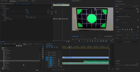

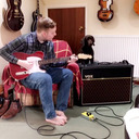
Finally we have finished our video piece. We have tried to balance humour and professionalism whilst keeping the purpose of the project clear and concise. We took it in turns writing the script, filming and editing. We also made sure we all appeared in the video in some shape or form. In the video I used an explosion from YouTube and some royalty free music written by Benjamin Tissot. I used Premiere Pros auto ducking system to make the music quieter whilst the voiceover is playing. Other effects I used were pitch manipulation, chroma keying and lens flares. The video was filmed on a GoPro HERO5 camera and the audio was recorded using an Audio Technica AT2020USB microphone.
0 notes
Text

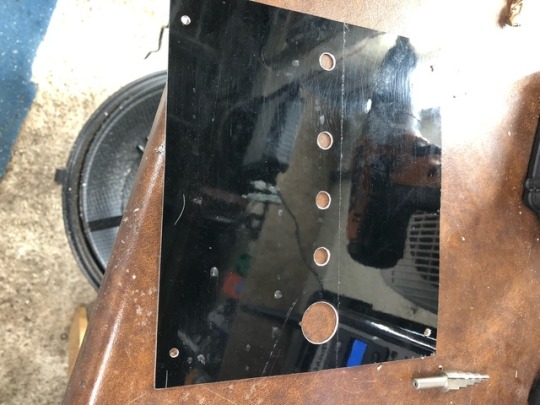
Finally it was time to make the top. I had a piece of sheet aluminium taken from a side panel of an old Land Rover. I measured it up and used the electric saw to cut the right shape out of it. Then using a scriber, I marked out where the switch and knobs would be going on the aluminium. After drilling the holes for them I also drilled 4 corner holes to allow the top to be fastened. I drilled 4 corresponding holes in the box top. I used a sanding block to remove the rough edges and smooth the corners. Then I used a deburring tool to get the burrs out of the drilled holes.

Finally I used some autoglym resin polish to clean the top up the best I could and hooked up all the potentiometers and the switch. It looked great!
0 notes
Text


Next I took some off cuts of wood from the garage and started to make the box. I cut the wood using a band saw. The base and sides were quite thick pine while the front and back pieces were made from some thinner board.
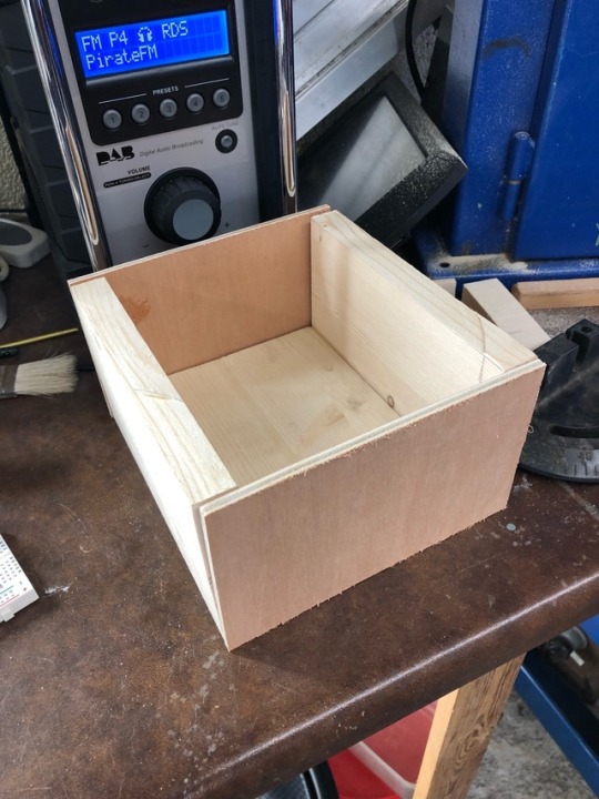
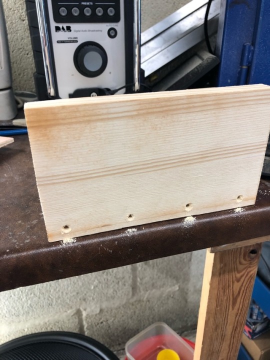

Next I lined it all up to make sure it was going to go together nicely. I drilled 4 holes in the bottom of each side piece and used screws to attach the sides to the base. Before I attached the front face I drilled out a hole for the arduino socket to fit through. Then I nailed the front and back faces on as this was substantial enough to hold them in place.
0 notes
Text
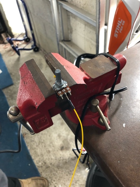
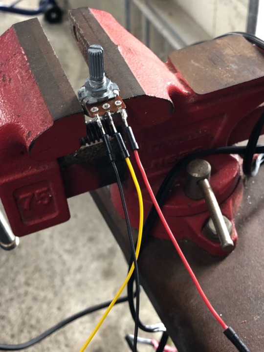

So before I constructed the case I decided to solder the wires onto the potentiometers and the switch. I used the vice to hold the potentiometer steady while I tinned the ends of the wire and the pins. Then I lined the wires up and quickly attached them to the pins, taking care not to damage the potentiometer by heating it up. I used the same system for the switch too. I decided to have a uniform colouring system for the wires. Red for positive and black for negative. The yellow wire was the analog connection.
0 notes
Photo


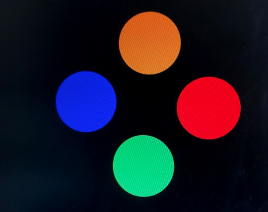
I watched a tutorial from Jack Solomon on OBJECT Lab 4 about setting up multiple serial inputs through Arduino and picking up the individual pieces in p5. Jacks demonstration of this is shown in the third image. He has created a function that will split the string of data whenever there is a comma. Then he uses two predefined sensor variables that are allocated to segments of the string. I took this initial code and manipulated it in a way that allowed me to use more inputs and I linked the inString variable to the inData variable that I already had. This meant I had the final configuration of four potentiometers and one switch. I decided to give each potentiometer a different look to correspond to our “weird” theme. All that’s left is to make the case and video it in action!
0 notes
Photo
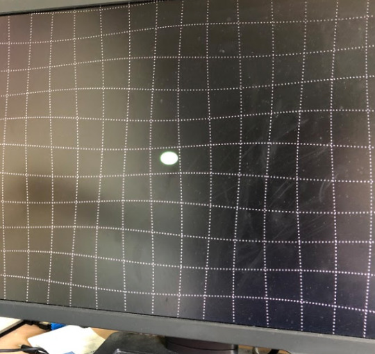
Once I had successfully got the p5 serial connections working I started to alter the visual aspects of the project. I started with just the singular potentiometer wired up which changed the scale of the circles on screen. This was a relatively standard procedure and didn't take much code to get working.
0 notes
Text
DIWO
One of the key elements I have been exploring in this module is the idea of DIWO (Do It With Others).
DIWO explores the ideas and possibilities of group work which is essential to this project. A lot of this revolves around teamwork of like-minded people. Luckily for me, my group members are very like-minded which has made decision making a lot easier. Also it allows us to work well as a team when we are creating elements of the project. This means that everyone is involved which is beneficial to all 3 of us. Many hands make light work as they say! Also it’s nice to get other peoples opinions on the work we have done as we can encourage each other to do better.
0 notes
Text
Familiar Faces
After researching Auduino we came up with another thinking point of our interface. How were we going to interact with visual elements but only using the interface that we’ve made? This made me think back to my previous coding module of DAT 405 where we used a JavaScript library called p5.js to create visual pieces of work. I quickly looked into connecting the arduino to a p5 script and to my amazement I discovered it was possible! By using an extension which creates a serial connection, you can quickly link the arduino file with the setup code to the p5 file and create some crazy looking patterns and shapes on screen. It will be interesting to see how well we can get this method of communication up and running and to what level we can push it to. Another thing that is important to think about is the aesthetics of the work. I have got some wood at home so I’m hoping to be able to work on putting together a housing over the weekend that our project can sit in. I want this to look sleek but also a little crazy to reflect the feel of our interface. It’s nice to see how our ideas are coming together and this week was definitely reassuring in terms of us being a well balanced group.
0 notes
Text
Synthesised
More work on the project this week has given us some great developments on the electronics front. We started off with a look into Auduino and how we can use potentiometers to control an audio synthesiser. Then I took the arduino software and looked into how it would be possible to manipulate the sound using motion sensors or flick switches. We have decided as a group that Sam is going to focus on our video, I am focusing on the physical side of things in terms of designing the casing and assembling the circuit while Ronan is going to work on the code itself. This is a good way for us to divide the work without having to overlap too much with eachother.
0 notes
Photo


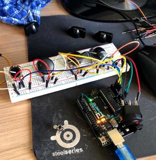
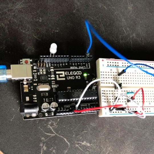
The third test I did was using a piece of code also created by Tom Igoe. The purpose of this one is a visualisation where the LEDs light in order depending on the resistance of the potentiometer. This would be a good base idea for part of our project. I am going to attempt to incorporate the ultrasonic sensor into this idea so it lights up as a user approaches. I think this will make the project appealing to passers-by. It also adds a good level of depth to the visual aesthetic of the interface.
0 notes
Photo
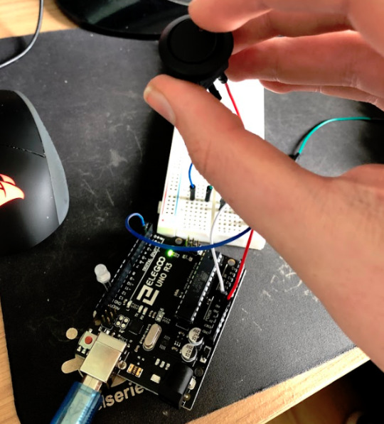
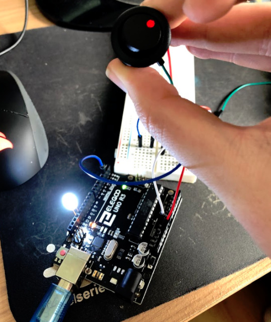
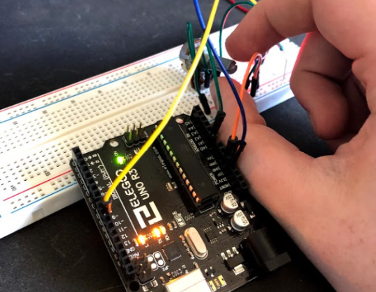
The next stage was to try and adjust the circuit to use some of the buttons and switches I’d collected from my dads workshop. The switch I chose was a universal switch which would be used on the dashboard of a vehicle to turn on some spotlights for example. Wiring this up was relatively easy. It was just a case of rewiring the patch cables from the 4 pin button to the switch. It worked immediately and I was pleased to see the light on the switch came on as it was pressed.
0 notes
Photo

I started my Arduino tests with a simple push button LED switch. This worked fine which was a good indicator that my Arduino was working efficiently. The script I used was created by DojoDave and Tom Igoe.
0 notes
Text
Broken Connections
So over the Easter break I have been trying to make progress with our prototype interface. I bought an arduino kit from amazon that contained lots of switches and buttons along with various motors, fans and sensors. The issue I’m having is with our concept. We are going for an interface that is scattered with all these various inputs but getting them to all work at the same time whilst connected to one arduino is not going to be easy at all. In the mean time I also purchased Adobe CC so that I can use premiere pro to create our video showcasing the interface. My group has been a little unresponsive in terms of communication. One of our members hasn’t made it to a single lecture. The other two are nice though and seem keen to get some good work done. The only issues are little nicks that are to be expected when you start off. That being said, I’m optimistic that we can get some good work done over these last few weeks. I’m going to really push for more meet-ups and help with the arduino and delve a lot deeper myself into the possibilities but also limitations of this idea. More to come.
0 notes
Text
Switching it up
So this week I bought our group an arduino kit to start our project with. The kit was fully equipped with patch cables, switches and even motors. I immediately installed the arduino software and began to work on some basic circuits involving buttons and switches. I had a few problems to start off with as I hadn’t done much circuit work since school. After a few watched tutorials and E-learning sites I managed to start some simple work with potentiometers. I will make the most of this new tech over the next week or so and attempt to get our prototype together in time for the 2nd May.
0 notes
Text
Finalised Idea
So the idea we have come up with is a direct replacement for a keyboard. All the keys however are replaced with various inputs. Buttons, potentiometers, pressure plates and kill switches will all play a big part in this. We want to create a board that has a certain crazy feel to it. This might include having labels that don’t correspond to the switches or a sheer volume and variedness of inputs. I personally really like the idea of a kill switch with a keyhole, similar to the feel of a nuclear launch facility from a movie. As far as the video side is concerned, we want to go very over the top almost like a Michael Bay movie! The video will still be demonstrating the interface clearly and concisely but adding this element of excitement and light humour will be a definite ‘non-traditional’ method to tie in with the project itself.
0 notes
Text
Post Research Results
After exploring some of the already existing physical interfaces that are available. We had a chat about where we’d like our project to go. We decided that if this interface was to be non-traditional we would go really chaotic with it. We want to make something durable but not necessarily practical. Something that will mean the user has to experiment to get different results.
0 notes