#fixed-value capacitor
Text
Multilayer ceramic capacitor chip, fixed-value capacitor, capacitor manufacturer
1206 47 uF 10 V ±20% Tolerance X5R Multilayer Ceramic Capacitor
#Capacitors#Multilayer Ceramic Capacitors#LMK316BJ476ML-T#TAIYO YUDEN#fixed-value capacitor#MLCCs#Ceramic Capacitors#what is multilayer ceramic capacitor#low-voltage RF#ceramic capacitor values#Capacitors ceramic
1 note
·
View note
Text
would quite enjoy being a robot actually. im not a stem man but if u told me i was secretly a robot id be like YAYYYYY and then start cutting wires in my chest until they did something
#remember that fucking stupid poll a while back abt 'which would u rather secretly be; a clone or a robot'#and so many ppl were like 'ummmmm clone is the objective right answer theres all these questions about personhood and' blah blah blah#i already know im not a person and i greatly value my individuality! it would be a great relief to find out that i'm a robot!!!!!#like that would b a reason im like this that isnt audhd and highly probable repression. thats hard to fix#whereas if i was a robot i could just watch a bunch of gameboy repair videos on youtube until i went ohhh i have a faulty capacitor#and then i could go in and fix that and cure my adhd. wizardous
7 notes
·
View notes
Text
My parents have installed an 8kWh battery backup because frankly it sucks not to have power 4-8 hours a day. Pretty much everyone in South Africa who can afford one is installing one! But it's really stupendously expensive and it makes me think about how ridiculous the people suggesting that grid scale storage is viable are.
Look. I don't think we will never be able to do grid scale storage. There's lots of promising new battery and capacitor technologies. I give it decent odds that in the next century someone will develop a battery that rivals kerosene for cost per kWh of storage. But whenever we talk about tools for solving climate change I feel like a lot of people forget that it's a pretty imminent problem!
If I told you "hey, I know you're looking at that Toyota Corolla so you can drive to work. Well, I'm working on a flying car. It's going to be so much faster, and it'll cost the same amount as a Toyota Corolla, and I'll have it ready in a few months. Look, I've got this tiny scale model to show you that it's on the way, please give me the money you were going to spend on the Toyota Corolla and I'll give you a flying car when it's ready." you would laugh at me. Every single engineering project comes in over budget and over time, if it's finished at all. Scale models are nothing when you need to solve big problems. Everyone understands this with bridges, why do they not get it with gridscale storage.
Every day some guy says "hey look we built a sodium battery pack it took our lab six months to build 100kWh worth but we totally promise that we'll have mass production down by 2025 please don't think about whether you are designing a future grid heavily dependent on fossil fuel baseloads we'll have huge batteries by then look there's the one in Australia it stores literally seconds worth of grid capacity." and I feel like I'm going insane.
This is not a technology that is "ready to go" this is the shit we make fun of when a university PR department claims they've cured cancer (in mouse cells (in a culture ( with additional marker proteins (and killed the healthy cells too whoops))))
All the current climate change targets are aiming for things in 2050 and it feels like gridscale storage gets used as an easy excuse for politicians who don't want to explain why they're making a grid that happens to be completely reliant on fossil fuels. They just go "oh we're investing in renewable technologies ;)" while sheepishly standing in front of the gas pipelines.
They might not even be industry shills! Some of them are but I think some of them are genuinely taken in by the renewables grift. They see the endless fields of wind farms when they visit the German countryside or whatever and think wow :) renewables really work :) we're going to fix climate change :) and have never understood an eqCO2/kWh value in their life.
People reporting on SMR and renewables say things like "Nuclear is too expensive and impractical compared to wind and solar which is why we're not investing in it" but that's only true if you believe you can run a grid on wind and solar alone! Otherwise you have to say the quiet "and hundreds of gas turbines with fuel storage on standby" part out loud.
78 notes
·
View notes
Note
Hello there! In one of your episode reviews, you said that Doc seems to base his self worth off of how people see his intelligence. Did you have any more thoughts on that?
Hi! Some additional thoughts for you:
So, I'm going to separate Cartoon Doc and Trilogy Doc while discussing my thoughts for this, since the characters are so different. But, yes, the "Retired" episode of the cartoon is entirely centered around Doc falling apart at the seams when a malfunction in one of his inventions informs him that he's used up nearly all of his brain power.
In just the span of a few hours, he comes to the conclusion that he's useless to his family, and they'd all be better off without him. In his mind, he's a burden if he can no longer use his intellect to create inventions that better the life of his family, and it pushes him to make the decision to leave altogether. Big thumbs down to Doc for abandoning his family.
BUT! It does say a lot about who he is if he thinks that not being "smart" equates to "having no purpose." And it's very clear that Doc thinks this way specifically about himself–not about other people. All the love and support he gives to his family apparently isn't enough on its own. Very sad! I can only assume that this dysfunctional line of thinking stemmed from the way he was raised and treated as a child and that he was only treated as if he had value when he was using his brain to contribute something. As far as I know, Doc's father isn't mentioned in the cartoons, but as I (jokingly) mentioned in my episode review, I can only assume Cartoon Erhardt is to blame here.
As far as Trilogy Doc goes, I don't really see him as having many insecurities tied to his intelligence. At least, not to the extent that Cartoon Doc does. Trilogy Doc doesn't strike me as someone who cares at all what other people think of him, and I definitely don't see him being duped by some silly brainpower machine that tells him he's used all his thoughts up.
I can, however, picture him reaching a point of giving up if pushed enough. Let's say, for instance, that the time machine hadn't worked that night at the mall. (I mean, assuming the speeding car didn't just plow into Doc and Marty, of course) If it hadn't run at all, or if it had malfunctioned in some other way, I think that'd be a crushing blow to Doc. He's poured decades into trying to harness the power of time travel. The process of exploring the science behind it and actually building the flux capacitor and making modifications to the car has consumed and bankrupted him. Doc's built a lot of nifty things over the years, but this is The Big One. He's been waiting all his life for this very moment! To have it all result in failure would do a number on him, I'm sure.
I could see him struggling with the aftermath. Maybe concluding it had all been pointless, and he'd given so much of his time to something that isn't even possible. Perhaps he'd just return to making little gadgets for around his garage or running his "scientific services" business, where he takes the occasional job fixing someone's television. This is where I think there could be some overlap between Cartoon Doc and Trilogy Doc–at least in the realm of not feeling smart enough or good enough to contribute anything meaningful to society. This also is where the information we have on Doc's father could for sure come into play and lead Doc to wonder if maybe his dad was right, and he should have given up science long ago.
Trilogy Doc is hardy, though, and I like to believe that he'd find a way to pick himself back up even if his biggest experiment ever didn't work. Maybe after taking some time to sulk (which would be understandable!) he'd buckle down even harder and be all the more determined to figure out how to get that DeLorean to travel through time. Besides, he's got an impressionable young friend who is lacking in the self-esteem department as it is. What message does it send Marty if the one guy who is always hammering in the "you can accomplish anything if you put your mind to it" message decides to abandon a goal after a failure? It'd be a hard teaching moment for sure, but I don't put it past Doc to be able to regroup and soon have a new game plan.
Thanks for the ask!
16 notes
·
View notes
Text
Review, teardown, and testing of LRS-75-24 Mean Well power supply
General description
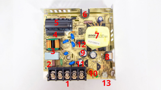
LRS-75-24 is a 24-volt power supply with a maximum current of 3.2 amperes. According to the manufacturer, the unit operates at a mains voltage of 100 to 240 volts without an additional switch. It has no PFC function. The supply measures approximately 4 × 4 × 1 1/5 inches (99 × 97 × 30 millimeters) and is made on a printed circuit board fixed to the base of the metal case. The top cover is perforated, and the holes are meant for passive cooling.
The input and output circuits are connected to a common screw block (1). From right to left, there are 3 terminals for the input line, neutral, and ground wires, and terminals 4 and 5 are the outputs: ground and +24V.
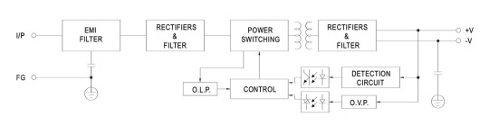
The input voltage goes to the fuse and inrush current limiter (2), then to the RF interference filter (3), and finally, to the diode bridge (4). The inrush current limiter has no markings; apparently, it is just an NTC. The rectified mains voltage is supplied to the 150 uF, 400V capacitor (5) and then to the flyback converter built on an MW03A controller (located on the back side of the PCB), a TK750A60F transistor (6), and a transformer (7).
The voltage from the secondary winding of the transformer is rectified by a Schottky diode HBR20150 (8) and supplied to storage capacitors 2×470uF 35V, and, through an additional LC filter (10) (11), goes to the output.
The feedback circuit is classic; with TL431 (on the other side of the board), the feedback signal is transmitted to the PWM controller through one of the optocouplers (12); the second optocoupler forms a backup channel for overvoltage protection at the OVP output. The installed electrolytic capacitors are designed for operating temperatures up to 220F (105C). The bulkiest of them, the input one, is held on the board with compound.
Build quality is good.
The power transistor (6) and diode (8) are pushed against the metal case using spring brackets to dissipate heat. Their own housings are insulated using special shells.
Test conditions
Most tests are performed using Metering Setup #1 (https://teardownit.com/posts/power-control-unit-for-testing) at 80F (27C), 70% humidity, and 29.8 inHg pressure.
The measurements were performed without preheating the power supply with a short-term load unless mentioned otherwise.
The following values were used to determine the load level:
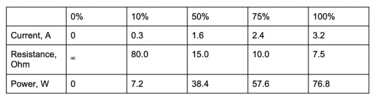
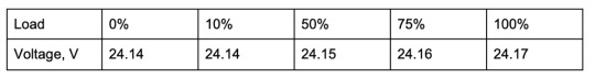
It should be noted that there is a slight overshoot; increasing the load slightly increases the output voltage.
Power-on parameters
Powering on at 100% load
Before testing, the power supply is turned off for at least 5 minutes with a 100% load connected.
The oscillogram of switching to a 100% load is shown below (channel 1 is the output voltage, and channel 2 is the current consumption from the grid):
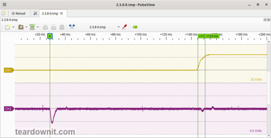
The picture shows three distinguishable phases of the power-on process:
When connected to the grid, the pulse of the input current charging the input capacitors has an amplitude of about 5.7 A and a duration of 6 ms.
Waiting for the power supply control circuit to start for about 117 ms.
(Output Voltage Rise Time) Starting the converter, increasing the output voltage, and entering the operating mode takes 6 ms.
(Turn On Delay Time) The entire process of entering the operating mode from the moment the device powers on is 123 ms.
(Output Voltage Overshoot) The switching process is aperiodic; there is no overshoot.
Power-off parameters
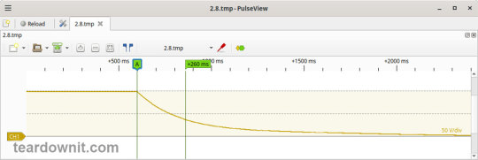
The power supply was turned off at 100% load, and the input voltage was nominal at the moment of powering off. The oscillogram of the shutdown process is shown below:
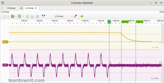
The oscillogram shows two phases of the shutdown process:
(Shutdown Hold-Up Time) The power supply continues to operate because the input capacitors hold charge until the voltage across them drops to a certain critical level, at which point maintaining the output voltage at the nominal level becomes impossible. The phase takes 16 ms.
(Output Voltage Fall Time) Reduction of the output voltage, stopping voltage conversion, and accelerating the voltage drop takes 19 ms.
(Output Voltage Undershoot) The shutdown process is aperiodic; there is no undershoot.
The amplitude of the current at 100% load before shutting down is approximately 3 A.
Output voltage ripple
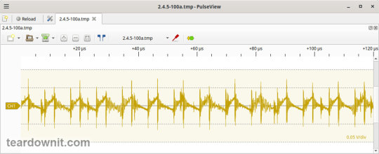
100% load
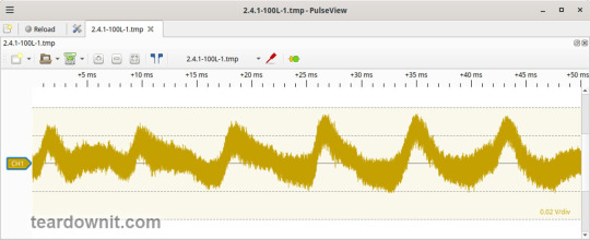
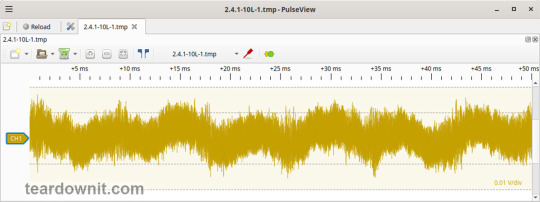
At 100% load, the low-frequency ripple is approximately 20 mV.
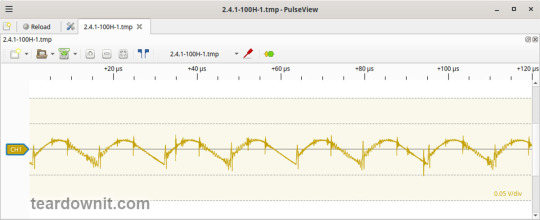
At 100% load, the ripple at the converter frequency is approximately 50 mVp-p.
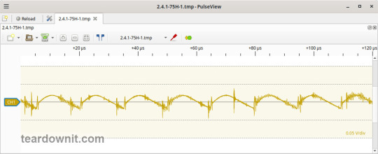
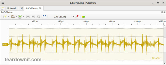
75% load
At 75% load, the low-frequency ripple is approximately 40 mV.
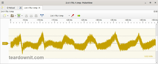
At 75% load, the ripple at the converter frequency is approximately 35 mVp-p.
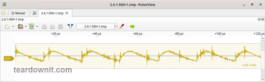
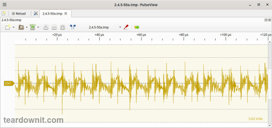
50% load
At 50% load, the low-frequency ripple is approximately 20 mV.
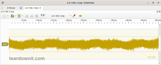
At 50% load, the ripple at the converter frequency is approximately 40 mVp-p.
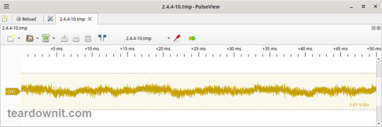
10% load
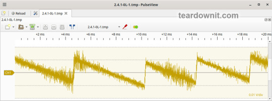
At 10% load, the low-frequency ripple is approximately 10 mV.
At 10% load, the ripple at the converter frequency is approximately 20 mVp-p, and the noise is 80 mVp-p.
0% load
The no-load current consumption measured with a multimeter is 18 mA. The current consumption in this mode is predominantly reactive. In the supply circuit, the input filter contains a 0.47 uF capacitor.
(Power Consumption) It is not possible to measure the exact active power consumption at a 0% load with a basic set of instruments (oscilloscope, multimeter, etc.).
At 0% load, the low-frequency ripple is approximately 10 mV.
At 10% load, ripples at the converter frequency are masked by the 90 mVp-p noise.

Dynamic characteristics
A mode with periodic switching between 50% and 100% load was used to evaluate the dynamic characteristics. The oscillogram of the process is shown below:
The supply’s response to load changes is a bit shaky. The magnitude of the response to load changes reaches 200 mV.
Overload protection
The claimed protection type is "hiccup mode, which recovers automatically after the fault condition is removed." This was confirmed during testing. When a short circuit occurs, the power supply periodically tries to turn back on and, if the overload is still present, turns off again until the next attempt. This operating mode reduces energy losses and heating during overload. Still, it does not allow the parallel connection of multiple power supplies with a common output.
The output current for the overload protection to kick in is 5 A.
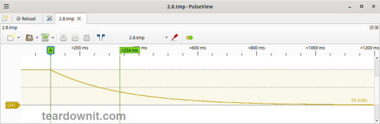
Input circuit safety assessment
(Input discharge) Safety assessment is based on the discharge time constant of the input circuits when disconnected from the grid; the value is 0.234 s. This means that when operating on a 120 V input voltage, the time required to discharge the input circuits to safe values (<42 V) will be 0.37 s:

Important: The result is valid for this particular power supply unit; it was obtained for testing purposes and should not be taken as a safety guarantee.
The leakage current at the ground pin is about 11 µA.
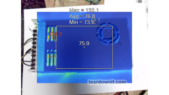
Thermal conditions
When operating with no load connected, no component overheating had been noticed.
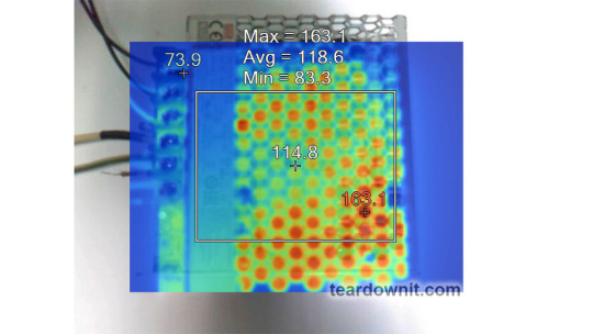
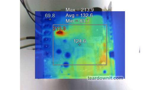
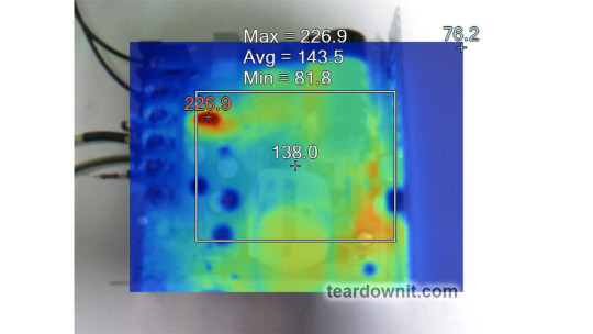
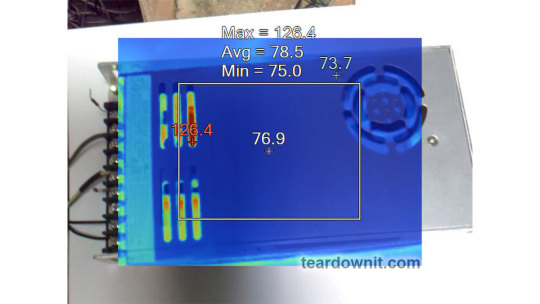
Thermograms were captured at three power levels: 80, 90, and 100%, fully assembled and with the lid removed. Thermal images show that the most loaded element of the block is the input thermistor (NTC), and its heating seriously stands out against the background of all the other components. At 80% load, it heats up to 197F (92C, 117F above ambient temperature). At 90%, it's 214F (101C, 134F above ambient), and at 100%, it reaches 227F (108C, 147F above ambient).
80% load


90% load
100% load

Conclusions
Overall, the LRS-75-24 is a solid unit. It's noise and ripple are acceptable for many applications, the output voltage is maintained accurately, and the build quality is decent. However, the dynamic characteristics of this power supply are not that good. When load pulses, one can notice large surges and quite some ripple, indicating some circuit design downsides in terms of its frequency characteristics.
For long-term operation, the load should be limited to 80–90% of the nominal one, especially during the hot season when ambient temperatures reach 95F (35C) or more.
Important: The results are valid for this particular power supply unit; they were obtained for testing purposes and should not be used to evaluate all the units of the same type.
0 notes
Text
Dynaco Renaissance.
Well sort of.
On a lap through the classified ads I found a clean looking but not functional Dynaco 400 amplifier for $400. That much for not working? Is this an indication of them becoming desirable? Not really, just a generation of audio people dying and things getting into estate sales. I should look into those.
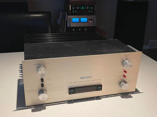
Back in the day I had this exact model I built from a kit. The guy wants $400 bucks for it but it needs major repair. By coincidence I have a full set of parts and pc boards for one of these. Those are spares for my Franken amp if it smoked. The only missing bits are the output transistors, and PS capacitors, I know where to get those. So I could fix it.
It has the right knobs and all the cosmetic bits which are often lost or damaged. The fundamental question is it worth fixing at that price?
It is prettier than a black box for sure. Oh and yes I would want to modify it to Franken status which disables the speaker protection and all that stuff. So strictly in the name of science I go looking for the value of these things fully operational and clean.
The prices on Ebay go from about $260 broken to $2500 CDN with the optional meters, (plus shipping). There are a couple near $600 claimed to be working perfectly. One is in Canada with only 50 bucks for shipping. So a working one for $650 all in. I take that to mean that $400 bucks needing a few hundred in parts and hours on the bench is too much money. The value of these as collectables is to leave them stock. The $2500 unit is with meters and is definitely collectable if that is your thing.
All these date from the early 1970s. The Dynacos were the equal of Crowns and better than Phase Linears according to the golden ears of the era. As is often the case people who have never heard them dislike them cuz they are old etc. This was also the era of Ampzilla and SAE who shared Mr James Bongiorno as the designer with Dynaco. Dynaco was first then SAE, then GAS (Ampzilla). They were good units.
Given the many kits of parts and upgrades and community support a lot of people share my good opinion of them. The base units all had a clever power limiting system that could be turned off, but is thought to degrade the sound a wee bit. The later 410 black boxes were stripped down to just the amplifier with no safety nets. My Franken-amp is from one of those. The mods I made were fairly brute force in the power supply with only capacitor tweaks in the amp circuit and the doubled up output transistors just like the 416. At its heart it is still a Dynaco 400. Well a Dynaco 416.
I can tell you with confidence mine is at least as good and in places better than my high end ARC Classic 60 tube amp dating from 1990. In twenty years the goal posts did not move very far if even at all. As far as I am concerned they still have not moved now in 2024.
1 note
·
View note
Text
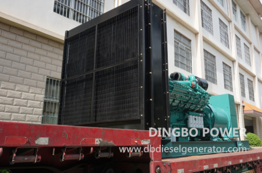
How to Solve Common Generator under Voltage Problems
Recently Dingbo Power received a few emails from users who encountered generator under voltage shutdown problems. According to their descriptions, the faults usually occurred after they started the generators for less than one minute. In fact, there are many possible causes of generator under voltage problem. This article covers some common causes and the solutions.
1.Low generator speed
In the generator set, the governor is an equipment associated with prime mover. The governor varies the amount of fuel delivered to the engine and adjusts the speed of prime mover. The voltage and frequency of a generator is largely determined by the speed they are running. When an undervoltage problem arises, you need to verify whether your generator set actually maintains its normal rated speed under all load conditions. Check the governor immediately and make sure it is in good condition and works properly. If the generator is running at a very low speed, try adjusting the prime mover speed of the synchronous generator with the adjustment screw to reach the rated value. If this is not the case, you need to look for other possible causes. It’s recommended that you call your dealer or ask a professional technician for help if you are not qualified.
2.Faulty AVR (Automatic Voltage Regulator)
The AVR is one of the essential elements that control the output voltage of the generator set. If there is something wrong with the AVR, a undervoltage may also appear. In this case, you can fix the problem by checking and making adjustments to the AVR. Start by checking the wiring of the ARV to see if there is any short-circuit or bad connection. If the wiring is normal, try making adjustments to parameters of the AVR according to the output voltage of the generator. In addition, defective rotor brushes may also result in the generator under voltage, you need to make sure they are in good condition and are making contact with the rotor. Replace the AVR if it can’t function well.
3.Overloading
Undervoltage conditions are usually caused by overloading of generator. When the demand for power exceeds the capability of the generator set, it's not surprising that the voltage drops. Under the circumstances, you can try making the measurements again with a smaller load to see if the voltage comes back to normal. Make sure the generator is sized properly for the load it is powering.
4.Loss of residual magnetism in the alternator
If new generator sets suffer bumpiness during transport or are left unused for a long period of time, it may result in the loss of residual magnetism or weak residual magnetism. To solve the problem, you need to regenerate the magnetism if this residual magnetism has been lost. Make certain how much voltage the excitation output of the generator AVR voltage regulator board is, and then connect the voltage source to the excitation output line for magnetization. Ensure the voltage types are corresponding and the polarity should not be reversed.
Other causes that may result in the generator undervoltage problems:
-Shorted windings: Megger test the alternator windings to highlight any issues. Check whether there is a short circuit or ground fault in the stator winding or if excitation connector is broken or connected incorrectly.
-Bad connections: Loose or eroding connections can cause resistance, resulting in voltage drop in the generator. If you are familiar with the equipment, check for loose electrical connections visually and reinsert any that are loose.
-A defective capacitor. A bad capacity will lead to a low voltage reading on the generator control panel. Test the capacitor with a multi-meter and replace it if it can’t work properly.
-Damaged rectitier diodes. You need to check alternator diodes and replace the broken diodes if there are any.
-Battery problems: If the generator's battery is failing or has a low charge, it can cause voltage drop. It’s necessary to replace it timely with appropriate battery model and capacity.
-other mechanical problems like fuel injection clogged or fuel filters clogged may also cause the problem.
Again, don't perform the above items if you are not qualified. Ask a professional for help and get the optimal solution. Keep in mind that regular maintenance of generator sets can help prevent such problems from occurring.
If you are looking for a reliable and trusted diesel generator, contact Dingbo Power now. We provide a variety of diesel generators which can suit your needs perfectly. The excellent warranty and after-sales support we offer will bring you peace of mind.
0 notes
Text
How to Accurately Measure Capacitance Using A Capacitor Tester

Capacitance refers to the ability to hold a charge. It is a medium for realizing the storage and release of static charges, with the characteristic of permanent charge storage. Capacitor components are widely used in power supply filtering, signal filtering, signal coupling, resonance, filtering, compensation, charging and discharging, energy storage, and power separation in circuits. According to its ability to accommodate charges, it is generally measured in Farads, and the international unit is Farads. Therefore, capacitors are essential components for electronics and power.
The role of capacitors: Bypass capacitors and decoupling capacitors are two devices that provide energy storage for local devices. Bypass capacitors can reduce load demand, make the output of the voltage regulator smooth, similar to a small rechargeable battery, and can be discharged and charged. The decoupling capacitor can smooth the edge signals of the device, so as to prevent the input signal from being too large and causing noise, and filter out interference in the output signal.
Large capacitors filter low frequencies, small capacitors filter high frequencies, filter out interference in the input signal, and the smaller the impedance, the higher the frequency passed through. Energy storage capacitors can collect charges and transfer them to the output end of the power supply. They can be units, parallel or series, to meet different power requirements. Therefore, measure capacitance is very important.
Capacitor meter is an important test instrument for detecting the parameters of capacitors in power supply engineering. It can accurately detect the capacitance of capacitors, test their characteristic parameters and accuracy, and ensure the normal operation of circuits. It uses an adjustable bridge circuit to measure the capacitance of the capacitor, and can better adjust the capacitor according to the test results to reach the best working state.
Working principle of capacitor meter:
The capacitor meter is a test instrument that uses synchronous sampling technology of standard and test capacitors, fault diagnosis procedure and fully automatic measurement process. It is not affected by the fluctuation of the power supply voltage, and can accurately and reliably measure resistors and capacitors, with high stability and repeatability.
Features of capacitor meter:
Capacitor meter can conveniently and quickly measure a single capacitor on site, without removing the connecting wire, thus avoiding a lot of time consuming work and damaging the capacitor. In addition, the capacitor meter will output a higher voltage than the capacitive table, which can improve the fault detection efficiency. In addition, the capacitor meter can not only measure capacitance, but also measure the inductance value of resistors.
LS6515EN Capacitor meter
A deeper understanding of the working principle of capacitor meter:
The capacitor meter directly measures the capacitive current from the secondary side of the power distribution PT, which makes the test safe, simple and fast, so that the instrument does not need to communicate with the primary side and can accurately and reliably monitoring data, and without making complicated safety measures and waiting for lengthy dispatch command. In addition, the capacitor meter injects the harmonic test signal at the PT’s open triangular junction, not only will not cause any influence to the relay protection and PT itself, but also avoids the 50Hz power frequency interference signal, the output end withstands the AC voltage of 100V, the system has single-phase grounding fault, and will not damage the PT and tester, making the test results more accurate and reliable.
Measurement method of capacitor meter:
This introduces the measure capacitance method of fixed capacitors from 10pf to 001uF. First of all, check the capacitors below 10pf, which can be qualitatively checked using the R * 10k gear of the universal meter, to determine whether there is leakage, internal short circuit or breakdown phenomenon of the capacitor; secondly, 10pf to 001uF fixed capacitors, universal meter should select R*1k gear, using two transistors (passing current should be small, type such as 3DG6, β value greater than 100), and red, black pens of multi-functional meter, respectively Connected to the emitter and collector of the bi-directional tube, to determine whether there is a charging phenomenon, and then determine its quality.
Read the full article
0 notes
Text
The top ten brands of copper row processing machines (how to choose from Hebei liquid pressure parent machine)
For example, the tension of the winding, the screen voltage, and the adjustment of the adjustable parts such as the starting position, and the adjustment of the starting position is an effective method in maintenance. By regulating the adjustable components, some injuries are corrected. For example, in a certain enterprise to repair a bus that has been used for many years, its system display screen is dull, and it is normal after adjusting the screen power supply voltage.
The leakage protector of the Top Ten Brand of the Top Ten Copper Machining Machinery is a current -current -type leakage leakage protection equipment. It is suitable for the power transformer neutral point grounding system (TT and TN systems), and it is also suitable for the ground to the ground. Some of the IT systems that are not grounded in neutral points with a large capacitor (non-phase-phase-phase shock is not applicable) The following editors will introduce the leakage protection of the copper row bending machine:
Plossal part: The copper row bending busbar machine uses a hydraulic transmission. The slider part is composed of a slider, the oil cylinder, and the mechanical block of the block. The left and right oil cylinders are fixed on the rack. Control the value by the CNC system.
Before using the ring -shaped parent wire equipment equipment, the power is connected to the air load. In the process, many details can be observed. The instructions check for each component to confirm whether each function is normal and effective. This is also a process of being familiar with machinery and equipment. After a preliminary understanding, you can debug the corresponding functions that need to be processed. Equipment force.
The processing accuracy of the precision machining technology has the processing accuracy of the NC plans machine has been increased from the original wire (0.01mm) to the micron level (0.001mm). Some varieties have reached about 0.05 μm. The accuracy can be stable to 0.05 μm, and the shape accuracy can reach about 0.01 μm. The special processing accuracy of light, electricity, chemistry and other energy can reach nano -level (0.001 μm). Optimized through the design of the machine tool, the machine tool parts components are optimized. Super precision processing and precision assembly, using high -precision full -loop control and temperature, vibration error compensation techniques to improve the geometric accuracy of machine tool processing, reduce the shape errors, surface roughness, etc. The process of processing.
Site function: Cutting, punching, bending, bending, standing bending, twice, flat pressure point, flat voltage, voltage cable connector and other molds can be switched in the station independent, supporting specifications.
According to the distinction of Qu Daokui, the structure space implementation of the mechanical device can be called "mechanical device" below 3 axis, not "robot". "Only when 6 axis is 6 axis belongs to the" robot "in dynamic sense. This means that the operating point can enable the operating device to reach a required job point in a three -dimensional three -dimensional space, and at the same time, it forms the job direction that is also in the three -dimensional three -dimensional space on the operating point.
0 notes
Text
Debug Any Electronic Circuit in Simple Steps
Debugging and Troubleshooting are essential skills for any electronic circuit designer. Whether you are working on a simple or complex project, you may get in issues with the passive and active elements in your circuit, such as resistors, capacitors, transistors, and op-amps. However, when glitches occur, debugging becomes a crucial skill for engineers and hobbyists. In this article, we will show you how to identify and fix some in circuit problems with these debugging and troubleshooting techniques.
We will discuss on the following 7 techniques which you should used to debug an Electronic Circuit:
Visual Inspection
Power supply requirements
Examine the passive elements
Examine the active elements
Use a breadboard and a prototype board for debugging
Use simulation software and debugging tools
Documentation and Notes
7 Techniques to Debug an Electronic Circuit
Visual Inspection of Circuit and Circuit Diagram
Start with a thorough visual inspection of the circuit board. You should refer to your circuit diagram and implemented circuit to check whether all the connections are made properly. Look for any obvious signs of damage, loose connections, or burnt components. Check for solder joints that may be poorly connected or shorted. A magnifying glass can be handy for spotting minute details that may be overlooked.
Power Supply Requirements
Check if the power supply you provide is sufficient for the circuit or device to operate. Ensuring the power supply requirements are fulfilled is an important step in debugging any electronic circuit. Ensure that the power supply is delivering the correct voltage and current to the circuit. Use a multimeter to measure the voltage at various points in the circuit. Abnormal readings would indicate a power supply issue, such as a faulty regulator or a short circuit.
Examine The Passive Elements
Passive components, which operate without the need for external power, come with elements like resistors, capacitors, and inductors. Evaluate these components by using a multi-meter or an ohmmeter to gauge their resistance, capacitance, or inductance. Utilize a continuity tester to verify the absence of short circuits or open circuits. You should check the recorded measurements with the values you outlined in your circuit power calculation or datasheet. If any problem arises, either you can change the defective component or check for any loose or impaired connections.
Examine The Active Elements
Active components, uses external power for operation, include elements like transistors, op-amps, and integrated circuits. If your circuit has these components then you have to debug them using a multimeter or an oscilloscope to measure their input and output voltages and currents. Additionally, a logic probe or a logic analyzer can also be utilized to examine their digital signals. Check the recorded values with the projected values provided in your circuit power calculation or datasheet. If any issue occurs either substitute the defective component or look for any biasing, feedback, or stability issues.
Using A Breadboard And A Prototype Board For Debugging
A breadboard and a prototype board serve as the best way in the diagnosis and resolution of circuit issues. A breadboard comes with holes and metal contacts, facilitating the effortless insertion and removal of components. You can easily make a small circuit from your main circuit on a breadboard and test if it is working fine. On other hand, a prototype board is equipped with copper traces and pads, offering the capability to solder components permanently. These tools enable you to build and debug your circuit easily, and make the changes required in PCB as fast as possible.
Using Simulation Software (Like Proteus) For Debugging
Simulation software and diagnostic tools like Proteus, Eagle, National instruments, etc, stand out as the best instruments for pinpointing and resolving circuit-related debugging. Simulation software helps to build the circuit and simulate its working in your PC, you can implement everything in these simulation software without any power hazard. Simulation software uses algorithms to model and simulate the behavior of your circuit and its components. You can see real time working of your circuit and take readings without implementing it on the hardware. You can also use diagnostic tools which enable the monitoring and control of variables and parameters within your circuit and components through software commands and breakpoints.
Maintaining Debug Documentation and Notes
Maintain detailed documentation of your debugging process. Maintaining documentation of your debugging process is an important step so that you can check in future if any problem occurs in the circuit. This document will help you guide on debugging and will save a lot of time in future testing. Record the steps taken, measurements, and any findings. This documentation not only aids in tracking progress but also serves as a valuable reference for future troubleshooting.
Conclusion
In conclusion we would suggest you to always follow the above discussed 7 steps if you want to implement a debugging process in your organization. Debugging electronic circuits requires a systematic approach, combining theoretical knowledge with practical skills. By following these steps and leveraging the right software and hardware tools, you can identify and resolve issues efficiently and can ensure the optimal performance of your electronic circuits. Remember to stay patient and persistent – debugging is often a process of finding and elimination, leading you closer to a successful running circuit. Happy debugging!.
At Campus Component, the best electronic components online store you can get top-quality electronic components, cutting-edge debugging tools, and expert technical support. Whether you need resistors, capacitors, oscilloscopes, multimeters, etc or guidance on intricate debugging processes, Campus Component is there!
0 notes
Text
The Hidden Costs of Delaying HVAC Repairs: A Financial Analysis
When it comes to maintaining your home’s comfort, your AC does a lot of heavy lifting. It is probably one of the most used electronic appliances in your home, and as such is more likely to get overworked and breakdown. Most people who have an HVAC system in their home have dealt with the hassle of getting it repaired when it, inevitably, stops working due to one malfunction or another. If the problem appears minor on the surface, then it is easy to fall under the misunderstanding that maybe getting the AC fixed isn’t an urgent matter. But regardless of the nature of the issue, whether it is a strange noise coming from the motors or the AC refusing to turn on at all, it is in your best interests to address the problem as soon as possible.
Here we will look at some of the main reasons why you should never delay getting your HVAC system repaired, and the financial consequences of doing so.
Higher Energy Bills
One of the most common signs of a malfunctioning air conditioner and also an obvious cost of delaying HVAC repairs is increased energy bills. Internal issues within the AC, such as a worn-out compressor or a refrigerant leak, can make the system work harder than it needs to, effectively spending more energy to cool your home and driving up your electricity bills. Initially, you may only notice an increase of a few dollars in your bills, but this can add up quickly over time.
Repairing the AC will restore its efficiency and reduce unnecessary energy waste. Do keep in mind that your AC inefficiency could be a result of its age as well, as older systems don’t have the many technological advantages that modern systems do and can consume more energy. By using an outdated cooling and heating system, you may be losing upwards of $200 every year.
Costly Emergency Repairs
The cost of getting your HVAC system repaired depends on many factors, such as the seriousness of the problem getting repaired and the complexity of the parts involved. But one other factor that many people forget about is the time of the year. During peak seasons like winter and summer, the demand for cooling and heating repair services is the highest as well. You may struggle to find any free expert technicians, and even if you do, you will likely be charged a premium for emergency HVAC services.
Maybe the part that needs replacing isn’t easily available due to the higher demand for AC parts all around, and you end up paying extra for it or worse, can’t get your hands on it at all. This is why the best course of action to take is to perform preventive maintenance and early repairs so that you don’t find yourself in a pickle at the wrong time.
Expensive Major Repairs
It’s difficult to say exactly how much your HVAC repair will cost, as the final cost is a combination of a multitude of factors. However, a key determiner is the internal component being repaired or replaced, and the price for these parts can vary drastically. If your HVAC problem is related to the fan motor, ignitor, or capacitor inside, then you can expect to spend a few hundred dollars on the repair.
But if a problem with these minor parts is left unrepaired, they could end up causing a malfunction in more important parts as well, such as the compressor, which can cost up to $3000 to fix. Looking at these numbers, it should be a no-brainer that the long-term cost-effective measure is to perform regular maintenance and repair on your AC so that small problems within the system do not get the chance to snowball into something bigger.
Decreased Property Value
Most residents do not associate their HVAC system with the value of their house, but the two are related to an extent. A well-maintained high-performance HVAC system adds a lot to your property’s value and can attract potential buyers more. The opposite is applicable as well. A worn-down AC system can be seen as a sign that the house was not taken care of, which will bring down its value to buyers.
While the value of your house may not be an immediate concern of yours, investing in a good HVAC system can generate an impressive return on investment in the future. It might also be worthwhile to consider upgrading to an energy-efficient AC for the best cost savings. To determine what kind of HVAC upgrade or repair would be the best for your house, contact professional HVAC specialists like The Chill Brothers.
Complete Replacement Cost
HVAC repairs can undoubtedly be expensive depending on the problem at hand. But in most cases, even the costliest of repairs will set you back significantly less than what a complete replacement would.
The average cost of HVAC repair is $410 according to Forbes, and can be a lot more or a lot less depending on the part, with compressors, evaporator and condenser coils costing the most. But a brand-new HVAC system, on the other hand, costs significantly more at around $8000 on average. HVAC systems last for about 15-20 years, and ignoring necessary repairs will undoubtedly shorten this lifespan, leading you to incur expensive costs of replacement that you potentially could’ve avoided just by being quick with repairs and maintenance.
Conclusion
Studies have shown that for every dollar ‘saved’ by deferring maintenance, there comes a four-dollar increase in future capital renewal costs. In simpler words, the money you save now by not repairing your AC will certainly come back in the form of higher costs later on.
Take all of the factors discussed here into account, and avoid falling into the trap of deferred maintenance. With many professional service providers giving 24-hour HVAC services nowadays, it’s easier than ever to get in touch with a specialist. It’s also not just a matter of energy efficiency and saving money, but maximizing the comfort and safety of your home.
#This Summer#Guest Author#Guest Blogger#Guest Contributor#Guest Post#Guest Writer#Best Ways To Prevent The Most Common Plumbing Problems#Plumbing Problems#broken pipes#leaking pipes#clogged toilets#garbage disposals#prevent drains from clogging#plumber in tinley park#tinley park plumbers#plumber in orland park#orland park plumbers#plumber in homer glen#homer glen plumbers#plumber in frankfort#frankfort plumbers#plumber in mokena#mokena plumbers#plumber in lemont#lemont plumbers#plumber in new lenox#new lenox plumbers#plumber in oak forest#oak forest plumbers#plumber in homewood
0 notes
Text
Chennai's Trusted Source for Washing Machine PCB & Capacitor Repairs
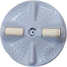
At Aldahome Appliances, we're proud to be the best option in Chennai for superior PCB and capacitor repairs for washing machines. Our dedication to quality work and satisfied customers distinguishes us in the appliance repair sector.
Expert Technicians:
Our staff of highly qualified experts at Aldahome Appliances has a great deal of expertise in identifying and resolving problems with the PCBs and capacitors in washing machines. We promise accurate repairs to return your appliance to peak functioning because we get the complex inner workings of these essential parts.
Quality Repairs:
Our primary goal is quality. You can rely on Aldahome Appliances to use only original parts and cutting-edge repair methods when you choose them for your washing machine repairs. Our goal is to give long-lasting solutions so that your washing machine continues to function well for many years to come. We don't just try to fix problems.
Fast and Dependable Service:
We are aware of the difficulty that a broken washing machine can bring. Aldahome Appliances is dedicated to offering dependable and timely services because of this. As soon as you contact us, our staff works quickly to arrange a convenient repair time, reducing the amount of time your appliance is out of commission.
Customer-Centric Approach:
Customer satisfaction is at the core of our business philosophy. At Aldahome Appliances, we believe in transparent communication and fair pricing. You'll be informed about the repair process, and our competitive rates ensure you get value for your money.
For Washing Machine PCB and Capacitor repairs in Chennai, trust Aldahome Appliances – where expertise meets reliability. Contact us today for a hassle-free and efficient solution to your appliance concerns.
#washing machine pulsator & roller hyderabad#washing machine drum spider bangalore#washing machine selector switch bangalore#washing machine spin tub & spin door bangalore
0 notes
Text
How valve amplifier repairs improve audio quality?
The timeless charm of valve amplifiers endures in the ever-changing field of audio technology, captivating both music lovers and audiophiles. These amplifiers are time-tested and renowned for their rich, warm sound signature and retro appeal. To preserve or even improve their audio quality, valve amplifiers could need periodic repairs, just like any other complex piece of machinery. We will examine how valve amplifier repairs can greatly improve audio quality in this blog post, going into the complex mechanisms that make these repairs an essential part of maintaining and enhancing sonic brilliance.

Repairs' effect on audio quality
Vacuum tube aging is one of the most prominent causes of a decrease in audio quality. These tubes may become less effective with time, which would result in a loss of warmth and clarity. A competent technician can revitalise a valve amplifier with a methodical valve replacement procedure. Switching to premium tubes can extend the amplifier's life and improve the clarity and depth of the sound it generates.
Within the amplifier, capacitors are essential for filtering and balancing the electrical impulses. Capacitors may lose some of their effectiveness with age, which can cause distortion and noise to appear in the audio output. High-quality, contemporary capacitors can replace obsolete ones, improving signal integrity lowering distortion and eventually raising the level of audio quality.
Essential parts that regulate the electrical current flow in the amplifier circuit are resistors. They may deviate from their initial values over time, which could impact how well the amplifier works. Expert technicians are capable of locating and swapping out malfunctioning resistors, guaranteeing that the amplifier functions within its intended specifications. This may improve performance overall in addition to restoring the original acoustic qualities.
A well-done repair may include signal route optimisation in the amplifier circuit. Maintaining a clear and continuous audio signal flow may entail cleaning or replacing input and output jacks. Furthermore, signal deterioration can be removed by fixing solder joints and connections, which will produce a more accurate copy of the original audio.
Conclusion
In addition to fixing problems, valve amplifier repairs open the door to the complete potential of this classic audio equipment. Expert technicians may restore a valve amplifier to its former glory and allow it to produce sounds that are on par with or even better than it did by carefully identifying and resolving problems like resistor drift, capacitor degradation, and tube attrition. The warmth and character of valve amplifiers are still valued by audio fans, and in the digital age, maintaining and enhancing the enchantment of analogue sound requires skilful repairs. For more information about valve amplifier repair, contact us today.
Disclaimer: This is generic Information & post; content about the services can be changed from time to time as per your requirements and contract. To get the latest and updated information, contact us today or visit our website.
0 notes
Text
Polymer Solid Tantalum Capacitor, Tantalum Chip Capacitor
TPF Series 330 uF ±20 % 6.3 V Surface Mount Polymer Solid Tantalum Capacitor, Capacitor types, tantalum capacitor values, What is a Tantalum Capacitor, Tantalum chip capacitors, 10uf tantalum chip, wet tantalum capacitors
LED Lighting Components, LED driver replacement, Lighting Solutions
100 - 277Vac, 90W, 24V, [0-10V, PWM], IP67 LED Driver, LED lighting systems LED Driver Modules, high power LED driver, LED Lighting Components, LED driver replacement, Lighting Solutions
Resistor network, Types of Fixed Resistors, Fixed resistor manufacturers
WSL Series 2512 50 mOhm ±1% 1 W ±75 ppm/°C Power Metal Strip Resistor, Resistor array chip, Programmable resistors, voltage dividers, chip resistor, Resistor network, Types of Fixed Resistors, Fixed resistor manufacturers
Electronic devices, dc power outlet, DC power plug, Through Hole Male Power Jack
Single Port 2 Conductors 3 Contacts 24 V 5 A SMT Unshielded Male Power Jack, DC power socket, plug adapter, dc power connector types, 12v dc connector plug, Electronic devices, dc power outlet, DC power plug, Through Hole Male Power Jack
Automotive timing device, Digital Clock, quartz watch crystal, Clock oscillators
FSRLF Series 32.768 kHz ±20 ppm 12.5 pF -40 to +85 °C Surface Mount Tuning Fork, Timing device, tuning fork crystal, tuning fork crystals, integrated circuit, Automotive timing device, Digital Clock, quartz watch crystal, Clock oscillators
1 note
·
View note
Text
The Best Skylake-X CPUs Motherboards
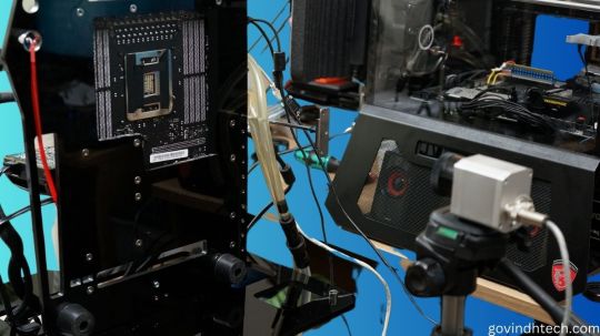
TIM gate, VRM disaster? Possible X299 motherboard faults and Skylake-X
In recent weeks, the leaf and video forest has been quiet. Even a VRM disaster or TIM gate (hot paste instead of lot) were discussed, but if you examine closely, the G… Thermal paste instead of solder Intel’s choice of improper (but cheaper) thermal paste instead of indium-based solder contributes to the cooling issue. Discuss the shelf life now… Default Settings Outside the Box, Cheats, Heat Long before launch, motherboard manufacturers made the first critique.
A typical all-in-one compact water cooler has dozens… We hold motherboard makers accountable. Blaming the imminent heat inferno just on Intel and the CPU cranked to its maximum limit would have been too short-sighted.
Noise across all media has been scarce in recent weeks. There was even discussion of a VRM disaster or TIM gate (thermal paste instead of solder), but the whole thing is just a long causal chain that starts with a hot-headed CPU. In theory, there are three. We try to make it simple, so one after another.
(1) Skylake-X is hardly coolable out-of-the-box in typical use due to excessive power consumption and thermal paste that limits optimal heat dissipation.
(2) The average user has little overclocking room, and many motherboards limit the CPU owing to design issues like insufficient external voltage converter cooling. Extreme overclockers barely work with modern hardware.
Usually, too much rhetoric is added, which doesn’t do credit to the potential purchasers’ difficulties.
Test setup and measurements
We’ll acquire a simpler Socket 2066 motherboard, make a vertical benchtable, and test (or not). We’ll look at the sensor values and origins of the respective areas, and we’ll use the infrared thermal imaging camera to test the board’s heating around the socket and voltage converter for plausibility.
We can also record the heating process in time-lapse videos. We also want to know if motherboard hotspots or heat transfer damage other components.
For safe sensor readings and smooth test setup operation, we use the newest motherboard BIOS and HWinfo in the latest beta version from v5.53–3190 (click on beta version while downloading!). We fixed or deepened certain features after a deeper inspection, manufacturer check, and community suggestions.
The board’s CPU power supply has 5 1 phases controlled by an International Rectifier IR35201. This multi-phase buck controller supports Intel VR12 and evidently VR13. The so-called doubling allows two circuits per phase with five phases, relieving the individual VRMs and equalising hotspots in area. This chip’s voltages and currents will be discussed later.
Each control circuit uses one International Rectifier IR3555 voltage converter. These highly integrated power stage chips include gate drivers, high- and low-side synchronous MOSFETs, and the Schottky diode. Unlike other MOSFETs, they have analogue temperature sensors. How else can you accurately measure these voltage converters’ temperatures without an IR camera?
MSI employs the Nuvoton NC6795D as a Super IO chip on the tested motherboard to record and provide sensor information. With a central thermistor between the power stage chips, the voltage converters’ temperature is likewise measured. Thus, we choose the back measuring point below this thermistor for our video acquisition.
The coils and capacitors of these voltage converter circuits and the board temperatures up to the CPU are also checked.
Sudden shutdown and downclocking
To better comprehend the future testing and the concerns that were often addressed too polemically in forums, we must realise that motherboard makers use safety devices. The Skylake-X is clocked down to 1.2 GHz at exactly 105°C at the thermistor (HWinfo under line MOS, Nuvoton NCT6795D) by our test board until the temperature drops below 90°C. Only then does it reach full velocity.
This makes sense since the flash point for the PCB material (FR4) is much higher, but the maximum continuous operating temperature is only between 95 and 105°C to avoid dry-out, bending, and conductor path hairline cracks in multilayer PCBs. This is good because graphics card makers normally have more (unnecessarily) nerve in this area.
In Intel’s Extreme Tuning Utility (XTU), this downclocking termed Thermal Throttling: Yellow, yes. What about Motherboard VR throttling status indicators? We must also give a little addendum regarding HWInfo values. It is less well known that the IR35201 also measures temperature. These results for VR T1 and VR T2 are much higher and appear to contradict the external sensor.
As usual, only the controller chip temperature was output. This would be equivalent to voltage converter temperatures VRM1 and VRM2 on graphics cards with PWM controllers (AMD cards commonly utilised them) in various tools. Usually, the chip measured itself there. However, with IR35201 and IR3555, it can be presumed that the IR3555’s voltage values and temperature inside are also utilised.
Before the XTU yellow warns of motherboard VR throttling, these values are limited to 125°C and the CPU is clocked to 1.2 GHz. Because voltages could run outside specifications and damage hardware above 135°C, the motherboard is turned down without notice.
CPUs also protect themselves. Multiple integrated digital temperature sensors (DTS) determine the computing core and package temperatures. The precision of these calculations rises with temperature. Below 40°C, it’s irrelevant, but from 80°C, it’s accurate. We can also see that core and package temperatures can cause clock throttling.
The power loss of the IVR the CPU’s voltage converters that provide partial voltages is also included in package temperatures. With strong overclocking and manual voltage increase, unanticipated limit overruns might occur quickly, which not all tools can detect. So the CPU throttles without the user knowing why. The IVR will be discussed shortly.
0 notes
Text
Review, teardown, and testing of RSP-320-24 Mean Well power supply
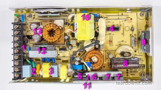
The RSP-320-24 is a 24-volt power supply with a maximum current of 13.4 amps. The supported mains voltage is from 100 to 240 volts without an additional switch. The supply measures 8.5 × 4.5 × 1¼ inches (215 × 115 × 30 millimeters), made on a printed circuit board fixed to the base's case. The top cover is perforated at the back near the connection terminals and on the front, where the cooling fan is installed. The fan starts spinning even if there's no electrical load. As the load increases, the fan speeds up, following the load current value. The fan sucks in the air and pushes it through the internal case volume to the perforated holes, including those on the side walls.
The input and output circuits are connected to a standard screw terminal block (1), from right to left: 3 terminals for the input line, neutral and ground wires, and 3 in parallel for common and +24V output. The input voltage from the terminals goes to the fuse (2), then to the pulse limiter (varistor), followed by the RF interference filter (3), and finally to the diode bridge (5). Next comes the active PFC, controlled by the PFC+PWM controller FAN4800 (4). Indeed, with a 234-volt AC power input, we get a rectified voltage on the storage capacitor (8) of 377 volts, approximately 47 volts more than without PFC Boost. The small voltage reserve is confusing since the capacitor installed is rated for 180 uF and 400 volts. All that's left is to rely on Nichicon's quality control.
The power part of the PFC is made of two parallel MOSFETs, IPP60R280P6 (7) and on an ultrafast diode 8A 600V STTH8S06D (6). The temperature sensor (11) is mounted above the PFC elements. The output voltage from the PFC is supplied to the two-transistor forward converter; the transistors are IPP60R280P6 (9) and are controlled by the same FAN4800 controller. The transformer (10) converter voltage is rectified and supplied to the LC filter. The output rectifier comprises eight diodes connected in two parallel groups (12). Total output capacitance: 2 pieces of 1000uF, 35V, designed for operating temperatures up to 220°F (105°C) (13). The output high-current circuits are reinforced with tinned copper busbars.
The control signal from the high-voltage side to the low-voltage side is transmitted through transistor optocouplers (there are two of them in the photo above the transformer hidden under a blob of the compound). One optocoupler is the primary regulation channel, and the second forms a backup channel for overvoltage protection, OVP.
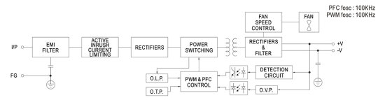
The block diagram in the datasheet shows the "Active Inrush Current Limiting" node. Still, we could not find components on the board that could perform such a role. Still, the inrush current limitation element is present, marked as RTH1 on the board, and installed near the boost inductor PFC; most likely, this is an ordinary NTC.
The high-voltage part of the board, starting with the capacitor (8) and ending with the transformer leads (10), is coated on the high-voltage side with a protective composite, presumably epoxy-based, which further increases electrical safety.
There is additional insulation and a thin sheet of fiberglass between the aluminum case and the board (solder side).
The overall build quality is good.
Test conditions
Most tests use metering circuit #1 (see appendices) at 80°F (27°C), 70% relative humidity, and 29.8 inHg pressure. The measurements were performed without preheating the power supply with a short-term load unless mentioned otherwise.
The following values were used to determine the load level:
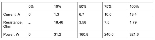
Output voltage under a constant load
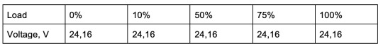
The high stability of the output voltage should be noted.
Power-on parameters
Powering on at 100% load
The power supply is turned off at least 5 minutes before the test, with a 100% load connected. The oscillogram of switching to a 100% load is shown below (channel 1 is the output voltage, and channel 2 is the current consumption from the grid):
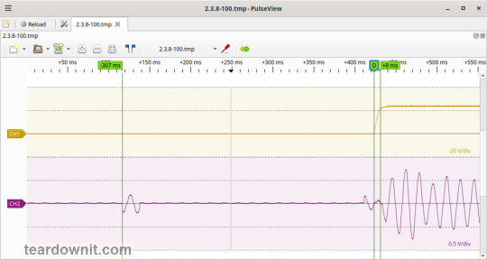
The picture shows three distinguishable phases of the power-on process:
The pulse of the input current charging the input capacitors when connected to the grid has an amplitude of about 2 A and a duration north of the mains voltage period.
Waiting for the power supply control circuit to start for about 300 ms.
(Output Voltage Rise Time) Starting the converter, increasing the output voltage, and entering the operating mode takes 8 ms.
(Turn On Delay Time) The entire process of entering the operating mode from the moment of powering on is 315 ms.
(Output Voltage Overshoot) The switching process is aperiodic; there is no overshoot.
Powering on at 0% load
The power supply is turned off at least 5 minutes before the test, with a 100% load connected. Then, the load is disconnected, and the power supply is switched on. The oscillogram of switching to a 0% load is shown below:
The picture shows three distinguishable phases of the power-on process:
The pulse of the input current charging the input capacitors when connected to the grid has an amplitude of about 2.2 A and a duration slightly longer than one mains period.
Waiting for the power supply control circuit to start for about 300 ms.
(Output Voltage Rise Time) Starting the converter, increasing the output voltage, and entering the operating mode takes 7 ms.
(Turn On Delay Time) The entire process of entering the operating mode from the moment of powering on is 320 ms.
(Output Voltage Overshoot) The switching process is aperiodic; there is no overshoot.
Power-off parameters
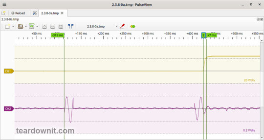
The power supply was turned off at 100% load, and the input voltage was nominal at the moment of powering off. The oscillogram of the shutdown process is shown below:
The picture shows two phases of the shutdown process:
(Shutdown Hold-Up Time) The power supply continues to operate due to the input capacitors holding charge until the voltage across them drops to a certain critical level, at which maintaining the output voltage at the nominal level becomes impossible. The phase takes 14 ms.
(Output Voltage Fall Time) Reduction of the output voltage, stopping voltage conversion, and accelerating the voltage drop takes 18 ms.
(Output Voltage Undershoot) The shutdown process is aperiodic; there is no overshoot.
Right before shutdown, the current waveform at 100% load is close to sinusoidal with an amplitude of 4.22 A.
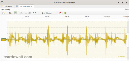
Ripple output voltage
100% load
At 100% load, the low-frequency ripple is approximately 3 mV.
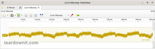
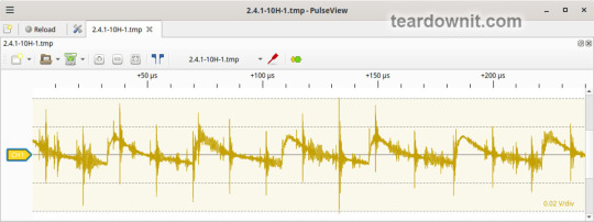
At 100% load, the ripple at the converter frequency is approximately 50 mVp-p, and the noise is 120 mVp-p.
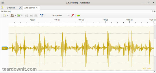
75% load
At 75% load, the low-frequency ripple is approximately 3 mV.

At 75% load, the ripple at the converter frequency is approximately 40 mVp-p, and the noise is 120 mVp-p.
50% load
At a 50% load, the low-frequency ripple is approximately 3 mV.

At 50% load, the ripple at the converter frequency is approximately 30 mVp-p, and the noise is 70 mVp-p.
10% load
At 10% load, the low-frequency ripple is approximately 2 mV.
At a 10% load, the ripple at the converter frequency is approximately 20 mVp-p, and the noise is 90 mVp-p.
0% load
No-load current consumption measured with a multimeter: 53.5 mA.
(Power Consumption) The first assumption of excessive standby power draw of more than 6.5 watts is wrong since the current in this mode is predominantly reactive. Indeed, the input filter in the circuit contains two capacitors with a combined capacitance of 1.5 μF. Measuring the exact active power consumption at a 0% load with a basic set of instruments (oscilloscope, multimeter, etc.) is impossible.
At 10% load, the low-frequency ripple is approximately 2 mV.

At 10% load, ripples at the converter frequency are masked by the 90 mVp-p noise.
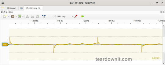
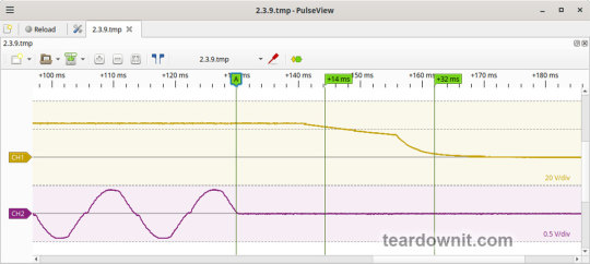
Dynamic characteristics
TA mode with periodic switching between 50% and 100% load was used to evaluate the dynamic characteristics. The process oscillogram is shown below:
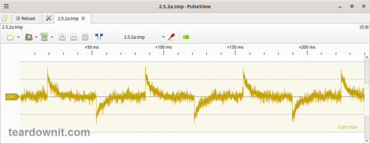
It is evident that the supply’s response to loading changes is close to aperiodic, and there is no overshoot, which indicates a good stability margin. The magnitude of the response to load changes is just 60 mV.
Overload protection
The claimed protection type is "hiccup mode, recovers automatically after fault condition is removed." This was confirmed during testing. When a short circuit occurs, the power supply periodically tries to turn back on and, if the overload is still present, turns off again until the next attempt. This operating mode reduces energy losses and heating during overload. Still, it does not allow the parallel connection of multiple power supplies with a common output.
The output current for the overload protection to kick in is 17 A.
Input circuit safety assessment
(Input discharge) Safety assessment is based on the discharge time constant of the input circuits when disconnected from the grid; the value is 0.26 s. This means that when operating on a 120 V input voltage, the time required to discharge the input circuits to safe values (<42 V) will be 0.41 s:
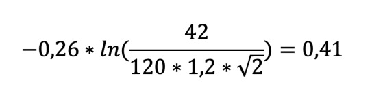
Important: The result is valid for this particular power supply unit; it was obtained for testing purposes and should not be taken as a safety guarantee.
The leakage current at the ground pin is less than 10 µA.
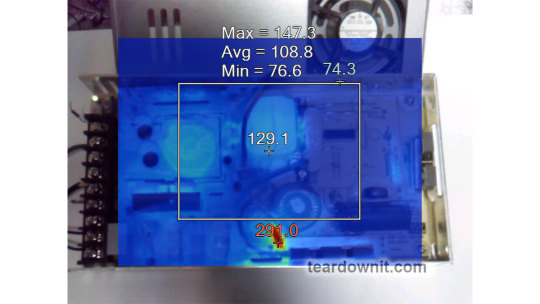
Thermal conditions
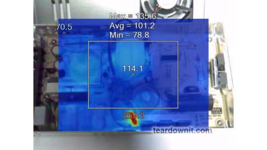
When operating with no load connected, no component overheating had been noticed. Thermograms were captured at three power levels: 80, 90, and 100%, fully assembled and with the lid removed. Thermal images show that the most loaded element of the block is the input diode bridge, and its heating seriously stands out against the background of all the other components.
Unfortunately, already at 80% load, the diode bridge heats up to an unacceptable level of 259°F (126°C), which is dangerous for long-term operation.
80% load

90% load
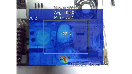
100% load
Conclusions
Overall, the RSP-320-24 is well-built: this power supply has good dynamic characteristics, low noise, and ripple, good accuracy in maintaining the output voltage, and is well put together.
The load should be limited to 70–80% of the nominal for long-term operation.
Important: The results are valid for this particular power supply unit; they were obtained for testing purposes and should not be used to evaluate all the units of the same type.
0 notes
Last Seen Blogs

little-tulips
Tulip

resinant
From Death to Resin

bluebladerose
Me and Mine, a Blog of sorts.

sexy-legs-crossed
Sexy Crossed Legs

i-just-existing
ROSES