
Last Seen Blogs


Text
ROLE OF COMPUTER AIDED ENGINEERING IN ADDITIVE MANUFACTURING
In all over the world, manufacturing sector has emerged as one of the high growth sectors on which millions of people are dependent because of their jobs. Throughout history, people have always been dependent on technology. Of course, the technology of each era might not have the same shape and size as today, but for their time it was certainly something for people to look at.
People would always use the technology they had available to help make their lives easier and at the same time try to perfect it and bring it to the next level. This is how the concept of the industrial revolution began. Right now, we are going through the fourth industrial revolution, also known as Industry 4.0.
Basically Industry 4.0 can be defined as “digitization of the manufacturing sector, with embedded sensors in virtually all product components and manufacturing equipment, ubiquitous cyber physical systems and analysis of all relevant data”. There are total 4 main factors on which Industrial revolution 4.0 is based.
1. Data, computational power and connectivity – i.e. low-power, wide-area networks, for example
2. Analytics and intelligence
3. Human-machine interaction – i.e., touch interfaces and augmented reality
4. Digital-to-physical conversion – i.e., advanced robotics and 3-D printing
3 D printing or Additive manufacturing is yet another technological advancement made possible by the transition from analog to digital processes. In recent decades, communications, imaging, architecture and engineering have all under gone their own digital revolutions. Now, AM can bring digital flexibility and efficiency to manufacturing operations.
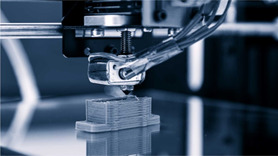
Additive manufacturing uses data computer-aided-design (CAD) software or 3D object scanners to direct hardware to deposit material, layer upon layer, in precise geometric shapes. As its name implies, additive manufacturing adds material to create an object. By contrast, when you create an object by traditional means, it is often necessary to remove material through milling, machining, carving, shaping or other means.
Although the terms "3D printing" and "rapid prototyping" are casually used to discuss additive manufacturing, each process is actually a subset of additive manufacturing. While additive manufacturing seems new to many, it has actually been around for several decades. In the right applications, additive manufacturing delivers a perfect trifecta of improved performance, complex geometries and simplified fabrication. As a result, opportunities abound for those who actively embrace additive manufacturing.
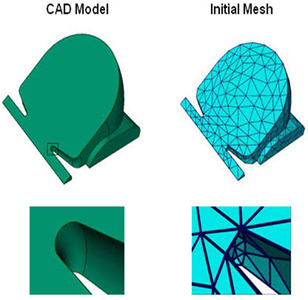
Computer aided engineering, or CAE plays key role in the process of additive manufacturing. CAE is mainly used to create the design which is later provided as an input to the machine. Rapid prototype is been made by the machine only after proper design of the object is achieved. Let us know more about such softwares which are commonly used for additive manufacturing technique:
ANSYS 3DSIM & FLEX:
One of the commonly used CAE software for additive manufacturing is ANSYS. This software along with other 2 software exaSIM and FLEX help users reduce the risks, trial and error of implementing a 3D printing workflow. It also hopes to speed up the installation and optimization of said 3D printing equipment. 3DSIM Company has launched the software exaSIM which is being used for 3D printing operation.
EXASIM ANALYSIS CAPABILITIES:
Ø Residual stress
Ø Distortion
Ø Build failure
Ø Tolerancing
FLEX capabilities:
Ø Ability to determine best process parameters based on material and 3D printer
Ø Optimization of part integrity, micro structure and properties
ANSYS ADDITIVE SUIT:
• MODULES:
TOPOLOGY OPTIMIZATION
Topology optimization in ANSYS Mechanical allows to:
Ø Take into account multiple static loads combined with optimizing for natural frequencies (modal analysis)
Ø Satisfy requirements for minimum material thickness
Ø Observe rules around feature direction (for machining operations)
Ø Easily validate results
Ø Easy extraction of optimized data in .stl format
STL FILE AND GEOMETRY MANIPULATION
This particular tool is used for
Ø Geometry repair
Ø Lattice creation
Ø Clean up of parts using the software’s faceted data tools.
STRUCTURAL AND THERMAL ANALYSIS AND DESIGN VALIDATION
Ø Full nonlinear, including transient, and linear analysis
Ø Capability to validate designs under a vast range scenario.
Ø Both thermal and structural loading conditions can be applied to models to understand performance and durability.
ADDITIVE PROCESS SIMULATION
Ø Predict Distortion
Ø Predict Stress
Ø Run Parametric Studies
ADDITIVE PRINT
Additive Print delivers unparalleled accuracy in predicting:
Ø Final shape of the printed part.
Ø Layer-by-layer distortion and stress.
Ø Optimal support structures.
Ø Distortion-compensated STL files.
Ø Potential blade crash.
ANSYS ADDITIVE SCIENCE
To determine optimum process parameters for metal additive manufacturing
**Capabilities of this module: **
Ø Analyze Porosity and Melt pools
Ø Predict Sensor Measurements
Ø Predict Thermal History
Ø Predict Microstructure
Ø Run Parametric Studies
Ø Track Phase Transformation
Materialise Magics
Materialise Magics is a versatile, industry-leading data preparation and STL editor software for Additive Manufacturing that allows you to convert files to STL, repair errors, edit your design and prepare your build platform.
MODULES
SINTER MODULE
With the Materialise Magics Sinter Module, you can:
Ø Nest parts quickly and automatically on multiple platforms
Ø Control the build time, height and density
Ø Avoid interlocking and colliding parts
Ø Create protective crates
Ø Re-nest from an existing configuration
SIMULATION MODULE
With the Simulation Module, you can:
Ø Predict areas prone to deformation, overheating and residual stresses
Ø Reduce the risk of build failures and make test prints redundant
Ø Speed up the search for the best parameter sets to build your parts
Ø Modification of support and orientation based on simulation results
Ø Counter-deform your parts to avoid deformations arising from the printing process
STRUCTURES MODULE
With Materialise Magics Structures Module, you can:
Ø Lower your powder consumption and production costs
Ø Add strength to the parts
Ø Reduce distortion (due to the heat generated during the build process)
Ø Create porous designs
Ø Available lattice structures include diamond, cross, diagonal etc
Ø Design your own unit cell structures to create a lattice structure
SUPPORT GENERATION MODULE FOR METAL (SG+)
With Materialise Magics SG+ Module, you can:
Ø Conduct heat and avoid deformation
Ø Optimize part orientation
Ø Recuperate powder
Ø Reduce build failures with build validation tools
TREE SUPPORT MODULE
With Materialise Magics Tree Support Module, you can:
Ø Improve the surface quality of metal prints
Ø Prevent part deformation with enhanced heat conduction systems
Ø Save time on finishing
Ø Use trees to create inlets in your lost-wax mold
IMPORT MODULE
With Materialise Import Module, you can:
Ø Manage the resolution of your data while importing it (for better STL quality)
Ø Import native color information
Ø Receive a repaired file after the import
AUTODESK Netfabb
Netfabb is software specially designed by AUTODESK for Additive Manufacturing applications. Netfabb software includes efficient build preparation capabilities alongside tools for optimizing designs for additive manufacturing, simulating metal additive processes, and planning for CNC post-processing.
Netfabb consists of following features:
Build Preparation:
Ø Import, analyze, and repair models:
Import models from a variety of CAD formats and use repair tools to quickly correct errors.
Ø Modify models for production:
Make your models production ready by adjusting wall thicknesses, smoothing rough areas, and more.
Ø Configurable build supports:
Identify areas that require support and use semi-automated tools to generate support structures.
Ø Mesh to CAD conversion
Convert organic, free-form mesh files to boundary representation models and make them available in CAD in STEP, SAT or IGES format.
Ø Automatic packing
Use 2D and 3D packing algorithms to optimally place parts within the build volume.
Ø Report generation
Create custom reports that include critical information for manufacturing and quoting.
Ø Advanced tool paths
Develop build strategies and define tool path parameters for maximum surface quality, part density, and speed.
Design optimization for additive manufacturing:
Ø Internal lattice structures
Create lightweight parts with performance characteristics specific to your application.
Ø Topology optimization
Generate forms that are optimized for stiffness and weight, based on the loads and constraints of the part.
Ø Integrated performance analysis
Test how your optimized designs will perform using built-in Autodesk Nastran simulation.
Ø Optimization engine
Automatically verify and optimize lattice and skin elements to meet load requirements and reduce weight.
Thus, we can say that there has been a lot of progress in the field of additive manufacturing day by day. As the technology progresses, it will be easy for us to analyze & manufacture the objects easily.
1 note
·
View note