servossim-blog
Servos & Simulation, Inc's Company Blog
Helpful Information for our potential and existing customers
18 posts
Don't wanna be here? Send us removal request.
Last Seen Blogs

amarivillakefalonia
Amari Villa Kefalonia

qvotable
Qvotable

ossi1971
Untitled

bullshit-basically-blog
We are nothing but specks of dust.

yahwehfflnc
FFL Yahweh NC
Text
5 Undeniable Reasons People Hate Motion Platforms
What are some of the reason that people in the simulation industry hate motion platforms? Let’s explore…
Cost! Why are they so expensive?
Installation… what is required to install a system and what support does it require?
Maintenance… Why does it cost so much to operate one?
Properly follow motion cues… Why doesn’t the motion platform follow the system?
Simulator sickness… why does this occur and does it need too?
Cost… yes, motion platforms are expensive, but why are they? Motion platforms require specialized engineering so that they operate properly. This includes mechanical, electrical and control engineers all working together to create a solution for the customer’s specification. Motion platform engineering houses are usually specialized in designing and manufacturing these systems. They typically have years and years of experience in the industry. They know all the details that are involved with creating a system.
Installation… most large scale motion platforms require heavy equipment to install and a team of people that are educated in the use of the heavy equipment and installation of the motion platform. This adds to the cost of the system.
Maintenance… most large scale motion platforms require a maintenance team to keep them operating properly. This adds to the cost of operation of the system if the maintenance team is kept on site. If not, someone has to be contracted to keep the system running. This adds to the cost of operating the system.
Properly follow motion cues… if the motion platform via software does not properly follow the motion cues from the Host computer (X-Plane, Prepared, MS Flight Sim, and the like), the system is basically worthless. It can induce motion sickness and keep the pilot from actually being able from flying the aircraft. If it does not follow motion cues for an entertainment type ride, the ride could possibly be ok, but not perform to the best of its ability.
Simulator sickness… why does this occur? When the motion platform does not respond to the visual system properly nor fly properly, it can cause simulator sickness. This lack of response can distract the pilot during training sessions and can cause the pilot to adopt certain counterproductive behaviors to prevent the simulator sickness from occurring. It can have post-training effects that can compromise the pilot after training. Check out this article on wikipedia for more information on simulator sickness.
So what can you do to fix these problems?
When looking into a motion platform for a system, one should consider all of these problems. Cost, installation and maintenance will always be a problem. The question one should ask themselves is what are they getting with the system? Can the manufacturer provide cost data for the system? Check out our Ultimate Checklist for buying a Motion Platform for more information on specifics to ask.
The manufacturer should know how to make the motion platform operate properly so that it follows the motion cues and keeps simulator sickness to a minimum. A good example of wether or not the motion platform is performing well is to have the pilot fly the system without the motion on and then with the motion on. If the pilot is having to overcorrect while flying the simulator, the motion is typically the problem. Making sure that the motion platform is properly tuned is critical to the simulation. This can be used for space docking, land vehicle training and the like as it applies to all of it. See our blog post on this exact problem and how we corrected it.
The motion cues for an entertainment ride, while not as critical as that for a flight simulator, should match the visual as closely as possible. It should not lag behind the visual. While the visuals account for more than the motion platform movement in rendering out the ride to the consumer, it should not be off. It will cause motion sickness to the rider. The system so be fluid, dynamic and smooth (unless the ride is suppose to be rough, but having the motion base nice and smooth and then injecting a frequency is so much easier then trying to get roughness out of the system and then recreate it). A high performing playback system is key to entertainment system.
1 note
·
View note
Text
Why you cannot build a 6DOF for $5k… and shouldn’t
cost per axis:
motor
steel - parts
linear motors versus non-linear
drive amplifier for motor
fidelity
what do you lose?
what do you gain?
why do you need it?
motion base control
what you actually require?
what do you require this?
analog versus digital?
In my travels on the internet, I have witnessed DIY’er attempting to make motion base platforms from various items. From drill motors to wood, these systems are ingenious, but in my opinion seem unsafe and will not last over the long term. Let’s explore why…
What does it take to build a motion base? At the least, one would require something to move the axis with. This is typically a motor of some kind. This can either be hydraulic, electric, pneumatic or magnetic. Hydraulic would be a little out of reach of a DIY’er due to requiring a pump, oil container and the like (hazmat anyone). Magnetic doesn’t hold a load very well. Pneumatic is hard to control with a servo loop (you either go or not) and the pump is loud. So the simple solution is an electric motor.
So which type of motor? AC or DC? DC motors are the simplest to control in my opinion, but can be expensive. AC motors require knowledge on how to obtain full torque at zero RPM. This seems easy (hey! Tesla Motor Cars is doing it, so why not me?) but, it isn’t. Many DIY’er don’t even consider AC motors for their systems due to being able to make a stable servo. If they even consider making a servo loop at all. We will get to why a servo loop is required in a moment… The motor also determines how much payload that you want to pick up.
So you have picked a motor… now what about the other parts. Is the actual driving mechanism going to be linear or non-linear? Linear means that the assembly moves up and down. Non-linear means that the motor uses some sort of crank and pushrod assembly. Linear assemblies are nice in the fact that there are less parts to design, but they have their flaws. One major flaw in a screw type linear mechanism is that the bearings that make the system move induce chatter into the system and the bearings wear out over time. Eventually, they will need to be replaced. Non-linear requires more parts to be designed, but the movement of the system, if designed properly, will be nice a smooth and should last basically forever. A gear box of some sort can be used with the motor to facilitate lifting the payload which has to be matched to the crank.
So now you have designed a working mechanism… so how are you going to drive it and know where it is? DC and AC motors require some sort of signal to know where to go and how fast (servo loop anyone?). Most motors have a matching drive amplifier. This has to be wired to the motor, to some sort of control device and to the feedback device. This is the servo loop. Why is this important? In order to control the axis, you have to know where the motor is and how fast it is going. In this way, you can control the position of the driving mechanism and how fast or slow it reacts. This is important. Everything reacts a little different. Different aircraft react differently to each other. Same with cars, boats and the like.
So now, what do we use to actually control the motor? Depends on the drive amplifier for the motor… typically, this is either an analog or digital signal from something. I have seen everything from a computer with a digital to analog conversion board to a PLC to a simple waveform from a signal generator. The better the resolution of the control signal, the better the system will respond. X-Plane and MFS send out data for the aircraft and to some extent, they actually send the information for the motion base. But, is this information correct for the system that you have designed
Do you have to design and write software to interface into the simulation software? Most of the time. The complexity of the software is dependent on how realistic you want the motion base to be. For example, an airplane’s center of gravity (where it actually rotates about) and a helicopter’s center of gravity are different. They require different math models for the motion base geometry to get the motion base to react properly. Is the system linear or non-linear for the driving mechanism? Does the user of the motion base platform require the non-linearity of the motion platform to be removed from the system? If so, the math that the software has to accomplish is very difficult which adds to the complexity of the software to control the motion base.
So all of that has been engineered… now what about something to mount the motors and the driving assembly plus whatever is required to mount the items to the whole assembly (like a top for example). The geometry for all of this has to be designed so that you get the angularity that is required by what you want to simulate. Sometimes this is quite large and sometimes this is quite small. The overhung load and the center of gravity of the payload has to be calculated to make sure that the geometry to the motor and the like can actually move the system.
Now, get all the parts designed and manufactured, engineer all the electrical, wire all of it, built it and tested it (don’t forget about your safety stops). So how much does all this cost? Depends on your design, but the biggest cost that DIY’er forget to take into account is the engineering, build and testing time. Those costs are high… very high. Most DIY’er do not take their actual time into account because its a hobby! But, those of us that actually design these systems, it is not a hobby, it is our business. It is our business to make sure that the system does exactly what it is designed to do. If we do not, we lose business and we could possibly hurt someone or something or worse.
So is building a motion base for $5,000 USD feasible? The simple answer is no.
So is $5,000 USD per axis feasible? possibly… as long as it is a basic design.
So a basic standard 6DOF motion base (just the motion base and the electronics, not the controller and software) would cost about $30,000 for an average for a single rider system (around 500 pounds) with about ±15˚ in roll and pitch. The cost does not reflect the cost for the controller, possible software and customization of the system.
So there it is… this is why motion base platforms are so expensive. There is extensive engineering that is involved with designing everything from the mechanical to electrical to software to make it all work.
So now that you know a few of the reasons behind designing a motion base platform system, you can understand why they are not inexpensive and should never be.
1 note
·
View note
Text
The Ultimate Checklist for Buying a Motion Platform
What does the motion platform use for moving the axis? Is it hydraulic, electric, pneumatic or something else
What materials are used to construct the motion platform? Are the correct materials used? where are the critical parts of the system?
What is required to drive the motion platform axis? What is the resolution?
What is being used for feedback and position location?
How does the software move the motion base?
Does the motion base accurately model what is being simulated?
What is included? does it come with a custom top? what warranty/technical support is provided?
Has the motion platform manufacturer taken into consideration the CG of your payload, the payload weight, the overhung load, the velocity, the accelerations and angularity required for your specification?
What fails first?
Easy to set up and maintain?
The answer to number one depends on the payload. Electric is the typical way to move a motion platform axis until the system requires a large payload. This is because of the inertia of the motors required for electric systems. If the inertia is too high in the motor, it might not be able to maintain a constant speed that is required to move the payload. Hydraulic typically used for very large applications, but they have limitations such as turn-around bumps and speed. Pneumatics are hard to control.
If the system is using linear actuation, does the actuator have built in stops? Does it have a braking system? What is the life expectancy of the actuator? These should be answered with a yes, yes, and a mean time between failure. If the company that you are asking these question of cannot answer them, move on.
If the system is using a non-linear actuation, i.e. a crank and pushrod, can the crank move freely around the shaft (360˚ of rotation) without interference to other parts of the motion platform? Does it have a braking system? What is the life expectancy of the actuator? These should be answered with a yes, yes, and a mean time between failure. If it cannot, move on. The designer of the motion platform has not done the design work necessary to build the system properly. The crank should be able to rotate freely.
Use of the proper materials is critical for all motion platform applications. Steel is commonly used. Stressproof and ETD150 for critical parts maybe used. Framework for supporting the motion platform and the payload should be engineered properly for the application. Typically, if it doesn’t look strong enough, it isn’t. Always ask if a stress analysis has been done for the system that you are inquiring about. You might have to pay for it, but it is better than wondering if some part of the steel might fail. Grade 8 or better hardware for mounting and installation of essential parts.
Most electric motion platforms require the use of an amplifier to drive the motor for the axis. Use of the proper amplifier for the electric motor is crucial for proper operation of the system. The better the resolution of the amplifier, the better the motion platform will feel. This does not apply to hydraulic systems which are typically analog in nature. For electric systems, 16-bit resolution on the amplifier is the best.
The feedback device is an essential part of the motion platform. It allows the user to know where the motion platform axis is. It is either an encoder, a feedback potentiometer or angle displacement transducer. If an encoder is used, it should have a large amount of resolution (4096 or better). If a feedback potentiometer is used, it should be of high quality with a sealed ball bearing for longevity. If it is an angle displacement transducer, it should be properly matched to the system. If the manufacturer is using something other than these, ask what it is. Do some research on the part and its application to see if it is a good fit for you.
Motion Platform Software… this is an issue. What do you want the motion platform to do? Do you need a sea state generator? Do you need it to run via a joystick? Do you need it to sync to a playback video? Do you need it to follow a real aircraft or other vehicle? Do you just want a SDK and take control for yourself? Can the manufacturer provide you with all the information that you might require in regards to software? In a non-linear system, can the software accommodate the non-linearity? All of these issues should be addressed by the manufacturer. Ask questions.
What exactly is included? Does it include a top and is that top customized? Does it include a controller and what exactly is in the controller? Does it include installation? Does it include a warranty and, if so, is an extended warranty available? Does it include technical support and how long does that support last? You should get a year warranty at the least.
Payload specifications are always a problem and should be handled on an individual basis. The manufacturer should ask what the payload is, how much it weights, what its dimensions are and if the CG of the payload is available. Overhung loads should be calculated to make sure that the motion platform can handle the load. If they do not ask these questions, move on. They should ask you for the specification that you require. These are critical to the manufacturer as it determines how the motion base needs to be built. Most of the time, standard motion base designs that are on the market meet the requirements for the consumer, but they should be checked by the manufacturer. The manufacturer should want to know this information to make sure that the system you are purchasing is correct for your application.
What fails first… if they cannot answer you properly, they might not know. In linear electric systems, it is usually the bearings in the linear actuator. In hydraulic systems, the seals and valves fail first. In non-linear systems, the computer usually fails first if properly designed. In pneumatics, the air pump fails first. Sometime the feedback device fails if improperly installed.
Is the system easy to set up and maintain? What is required to install the system? What is the maintenance for the system? The manufacturer should be able to supply the consumer a manual for the system. They should be able to inform you as to what type of flooring is required for proper installation. They should be able to tell you the power requirements or be able to change the input power to the consumer’s specification. Maintenance and parts replacement on the system should be easy, straightforward and explained in detail in the manual. The manufacturer should be able to supply a generic manual for inspection as long as the consumer realizes that this is just a sample of what their actual final manual will be.
1 note
·
View note
Text
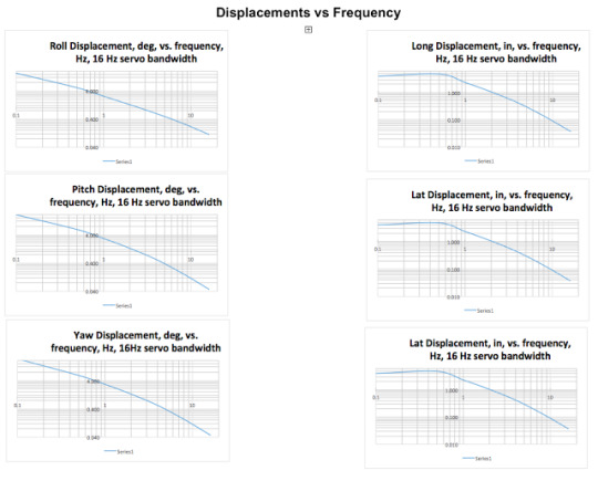
Frequency Response of our Motion Base Servo
The Engineering Team at Servos & Simulation, Inc., has analyzed the performance of one of our motion base designs. The plots for the performance show the maximum position as a function of frequency, the maximum velocities as a function of frequency, and the maximum accelerations as a function of frequency. The servo has an inner rate loop using the encoder on the motor for feedback allowing the servo to have a bandwidth of more than 40 Hz. The outer loop is a position loop with a bandwidth of 4 Hz. The position loop gain is limited by the gain available in the drive amplifier (power amplifier that drives the motor). Servos’ engineers add electronics to the servos and increase the gain by at least a factor of 4 which increases the position loop bandwidth to 16 Hz.
The structure of the motion base is stiff enough that it does not limit the bandwidth of the position loop. This includes the motor/gearbox. Since the structure is stiff, the bandwidth does not need to be limited to less than 16 Hz. The backlash in the gearboxes has been reduced to almost zero. This is necessary since at high frequency the motor movement is quite small. If the gearboxes had any significant backlash, the gearbox output shaft would not move. Servos’ engineers reworked the stock gearmotors to successfully remove the backlash from the gearmotors.
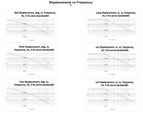
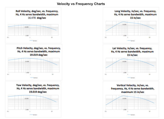
Another set of plots shows the motion base performance with a 16 Hz position loop bandwidth. As can be seen from the plots, the high frequency response is much better with a 16 Hz bandwidth than with a 4 Hz bandwidth.
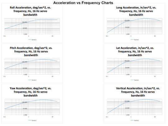
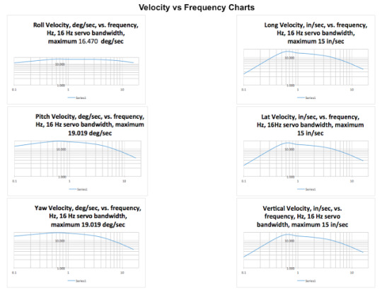
In these cases, the roll velocity is limited to 16.47 deg/sec, and the roll acceleration is limited to 230 deg/sec^2. Pitch and yaw are similarly limited. The Longitudinal velocity is limited to 15 inches/second and the acceleration is limited to 188 inches/second^2. Lateral and vertical are similarly limited. The velocity and acceleration limits can be increased within limits by changing the motors and gear ratios in the gear boxes.If you would like more information on our entire product line, please contact us at [email protected] or check out our web site at www.servos.com.
1 note
·
View note
Text
How does one precisely control a motion base?
How does one precisely control a motion base so that the user can know where the motion base is in space and can modify where the centroid of the moving platform coordinate system is in space?
Servos and Simulation’s engineers were recently presented with that exact problem. To compound the problem, Servos & Simulation’s motion base platform designs are non-linear in nature. This makes modeling the motion base platform for its math model very complex.
Servos and Simulation’s engineers have designed, programmed, and tested precision software to control our motion bases. Since there is no closed form solution to a non-linear Steward Motion Platform, a specially designed math model was developed to take the commanded roll, pitch, yaw, X (longitude), Y (lateral), and Z (vertical) commands from the host computer and sends control signals to each of the six non-linear actuators on the motion base to instruct the motion base to accurately follow the commands. The software takes care of all the non-linearities of the cranks and pushrods. In addition, the software allows the center of the moving platform coordinate system to be moved anywhere. For example, the center of the moving platform coordinate system can be moved 20 inches above the center of the moving platform, and roll and pitch will be centered about this new coordinate center in such applications for aircraft pilot feel and realism or off the nose in missile testing scenarios. With customization the software can determine the location of a point(s) on a Unit Under Test in free space such as in antenna testing.As part of the Precision Control Software, Servos and Simulation’s engineers have also developed a Dynamic Software Evaluator package that reads the feedback pots from each of the six actuators and calculates the roll, pitch, yaw, X, Y, and Z position of the motion base. The roll, pitch, yaw, X, Y, and Z positions can be sent to the host computer so the host computer knows exactly where the moving platform of the motion base is at any time.
The Control Software has an iteration rate or 1KHz but the host can send data anywhere from 200Hz up to the 1KHz. Typical bandwidth of the Control Software is around 3 to 5Hz.A separate Server Module handles the exchange of data to and from the Host to the Precision Control Software. Through a special software command set, motion can be started or halted, communications turned off or on, moved to specific locations etc. via the Server Module. The Server Module is also responsible for reporting position data from the Dynamic Evaluator back to the Host.These two software programs (Precision Controller and Dynamic Evaluator) are independent of each other but are memory mapped to work seamlessly between the Server Module, Precision Controller and Dynamic Evaluator. Either one can be used (with the Server Module) by itself or used together. As the Server Module is responsible for all communication, both software programs (Precision Controller and Dynamic Evaluator) are completely unaware of user inputs and rely solely on inputs derived from Host communications.
For more information on our entire product and service line, please check out our web site at www.servos.com or email us at [email protected].
1 note
·
View note
Photo
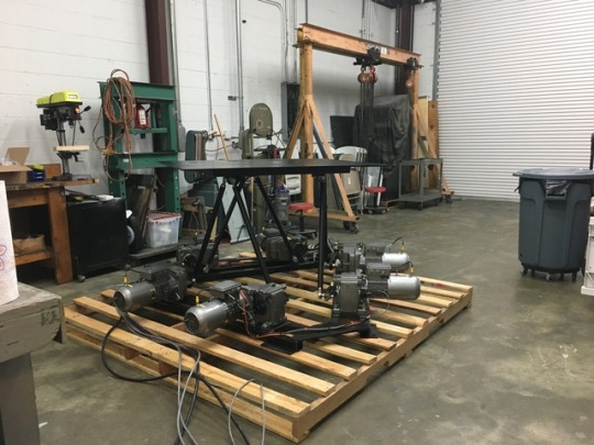
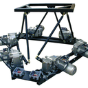
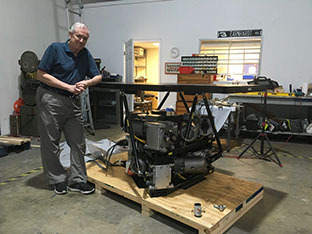
Almost ready to ship this six axis motion base with a 1000 payload to a customer. They required 30Hz and we delivered. Contact us for your engineering needs today!!
1 note
·
View note
Video
youtube
(via https://www.youtube.com/watch?v=svKkuWaEkNQ) High Frequency motion base platform (6DOF). This system will run at any frequency up to 30Hz with full motion. This is an upgrade to our standard system. If you would like more information on our full range of standard system, check out our web site at www.servos.com. If you would like information on a custom system like this one, please contact us directly through our web site.
1 note
·
View note
Text
What is the Real Cost of Upgrading a Feedback Control System?
Quite often, when systems are upgraded either for reasons of replacing parts that are no longer in the support system or improving performance, the cost of supporting the new system is neglected.
What sort of support from the manufacturer is available and at what cost?
What is the MTBF of the new equipment?
Is there any on-going maintenance that must be performed on a regular basis?
Such things make an inexpensive purchase price end up costing much more than a higher priced unit.
An excellent example covering the “Buying a Motion Platform” may be found at the following link:https://www.linkedin.com/pulse/ultimate-checklist-buying-motion-platform-rachel-baker
Since that covers the motion system quite thoroughly, let’s talk about the feedback control loading of the flight stick, yokes, pedals, throttle, toe brakes and the like of non-fly-by-wire simulators.
Many of the same performance factors of motion bases need to be addressed in regarding to feedback control loading systems.
Feedback Control Loaders can be very inexpensive for simulators that require little or no FAA approval. Such loaders can be considered simple springs; you pull or push on a control and it reacts as a spring or bungee cord. These are what could be referred to as “Entertainment” loaders and can be purchased for well under $500 USD but in no way qualify as Feedback Control Loaders for pilot training in a simulator.
As the quality (or rating) of the simulator systems increases, how much fidelity the system has becomes more and more important. A good read on the Psychology of Simulation can be found in R. T. Hays/M.M. Singer’s book “Simulation Fidelity in Training System Design” subtitled “Bridging the Gap Between Reality and Training.”
The bottom line - the simulator must represent what the aircraft or mechanical device feels like when in actual operation. Whatever the pilot/operator is trained to do in the simulator, it must represent exactly what it is in real life. If the pilot/operator is told, during training, to not pay attention to that "buzzy” feel might lead to that buzzy noise of an off-balance turbine being written off as normal resulting in death or injury in real life. This is why fidelity of the Feedback Control Loader is crucial. Thus, we get back to the fidelity as Hays’ book references. Poor fidelity equals poor performance.
So, what is GOOD fidelity? For that, let’s refer to FAA Class A and higher full-flight simulators. The one performance factor that describes the whole thing is the throughput of the system… i.e. how fast can the system take a sample, do math on the sample and output the result repetitively?
Servo feedback control engineers typically agree that the higher the throughput is of a system, the easier it is to stabilize the servo which keeps the servo stable in a system. As the frequency of samples decreases, the servo loses its ability to subdue inherent instabilities of the system such as noise, springiness of linkages, slop (loose bearings) in connecting rods etc. As a minimum, 4,000Hz would be suggested here and higher if possible.
Bottom line is this, a poorly design Feedback Control Loader is going to be with you for a long, long time. At what cost to pilot training, maintenance and upgrades will this affect the entire simulator program as a whole.
(1 - non-moving numerical ratings 1 thru 7 and moving ratings A thru D with “D” being the highest rated)
For more information on our Feedback Control Loader or Motion Base Platform product lines, please visit our web site at www.servos.com.
1 note
·
View note
Text
Design World Article
Design World has featured an article with us and Sensoray who provides us with one of the best analog I/O, digital I/O computer card that runs all of our product line. Check it out here: http://www.motioncontroltips.com/case-study-motion-platform-maker-standardizes-io-measurement-control/
1 note
·
View note
Text
What is the Real Cost of Upgrading a Feedback Control System?
Quite often, when systems are upgraded either for reasons of replacing parts that are no longer in the support system or improving performance, the cost of supporting the new system is neglected.
What sort of support from the manufacturer is available and at what cost?
What is the MTBF of the new equipment?
Is there any on-going maintenance that must be performed on a regular basis?
Such things make an inexpensive purchase price end up costing much more than a higher priced unit.
An excellent example covering the "Buying a Motion Platform" may be found at the following link:https://www.linkedin.com/pulse/ultimate-checklist-buying-motion-platform-rachel-baker
Since that covers the motion system quite thoroughly, let's talk about the feedback control loading of the flight stick, yokes, pedals, throttle, toe brakes and the like of non-fly-by-wire simulators.
Many of the same performance factors of motion bases need to be addressed in regarding to feedback control loading systems.
Feedback Control Loaders can be very inexpensive for simulators that require little or no FAA approval. Such loaders can be considered simple springs; you pull or push on a control and it reacts as a spring or bungee cord. These are what could be referred to as "Entertainment" loaders and can be purchased for well under $500 USD but in no way qualify as Feedback Control Loaders for pilot training in a simulator.
As the quality (or rating) of the simulator systems increases, how much fidelity the system has becomes more and more important. A good read on the Psychology of Simulation can be found in R. T. Hays/M.M. Singer's book "Simulation Fidelity in Training System Design" subtitled "Bridging the Gap Between Reality and Training.”
The bottom line - the simulator must represent what the aircraft or mechanical device feels like when in actual operation. Whatever the pilot/operator is trained to do in the simulator, it must represent exactly what it is in real life. If the pilot/operator is told, during training, to not pay attention to that "buzzy" feel might lead to that buzzy noise of an off-balance turbine being written off as normal resulting in death or injury in real life. This is why fidelity of the Feedback Control Loader is crucial. Thus, we get back to the fidelity as Hays' book references. Poor fidelity equals poor performance.
So, what is GOOD fidelity? For that, let's refer to FAA Class A and higher full-flight simulators. The one performance factor that describes the whole thing is the throughput of the system… i.e. how fast can the system take a sample, do math on the sample and output the result repetitively?
Servo feedback control engineers typically agree that the higher the throughput is of a system, the easier it is to stabilize the servo which keeps the servo stable in a system. As the frequency of samples decreases, the servo loses its ability to subdue inherent instabilities of the system such as noise, springiness of linkages, slop (loose bearings) in connecting rods etc. As a minimum, 4,000Hz would be suggested here and higher if possible.
Bottom line is this, a poorly design Feedback Control Loader is going to be with you for a long, long time. At what cost to pilot training, maintenance and upgrades will this affect the entire simulator program as a whole.
(1 - non-moving numerical ratings 1 thru 7 and moving ratings A thru D with “D” being the highest rated)
For more information on our Feedback Control Loader or Motion Base Platform product lines, please visit our web site at www.servos.com.
1 note
·
View note
Video
youtube
(via https://www.youtube.com/watch?v=svKkuWaEkNQ) High Frequency motion base platform (6DOF). This system will run at any frequency up to 30Hz with full motion. This is an upgrade to our standard system. If you would like more information on our full range of standard system, check out our web site at www.servos.com. If you would like information on a custom system like this one, please contact us directly through our web site.
1 note
·
View note
Photo
Almost ready to ship this six axis motion base with a 1000 payload to a customer. They required 30Hz and we delivered. Contact us for your engineering needs today!!
1 note
·
View note
Text
How does one precisely control a motion base?
How does one precisely control a motion base so that the user can know where the motion base is in space and can modify where the centroid of the moving platform coordinate system is in space?
Servos and Simulation’s engineers were recently presented with that exact problem. To compound the problem, Servos & Simulation’s motion base platform designs are non-linear in nature. This makes modeling the motion base platform for its math model very complex.
Servos and Simulation’s engineers have designed, programmed, and tested precision software to control our motion bases. Since there is no closed form solution to a non-linear Steward Motion Platform, a specially designed math model was developed to take the commanded roll, pitch, yaw, X (longitude), Y (lateral), and Z (vertical) commands from the host computer and sends control signals to each of the six non-linear actuators on the motion base to instruct the motion base to accurately follow the commands. The software takes care of all the non-linearities of the cranks and pushrods. In addition, the software allows the center of the moving platform coordinate system to be moved anywhere. For example, the center of the moving platform coordinate system can be moved 20 inches above the center of the moving platform, and roll and pitch will be centered about this new coordinate center in such applications for aircraft pilot feel and realism or off the nose in missile testing scenarios. With customization the software can determine the location of a point(s) on a Unit Under Test in free space such as in antenna testing.As part of the Precision Control Software, Servos and Simulation’s engineers have also developed a Dynamic Software Evaluator package that reads the feedback pots from each of the six actuators and calculates the roll, pitch, yaw, X, Y, and Z position of the motion base. The roll, pitch, yaw, X, Y, and Z positions can be sent to the host computer so the host computer knows exactly where the moving platform of the motion base is at any time.
The Control Software has an iteration rate or 1KHz but the host can send data anywhere from 200Hz up to the 1KHz. Typical bandwidth of the Control Software is around 3 to 5Hz.A separate Server Module handles the exchange of data to and from the Host to the Precision Control Software. Through a special software command set, motion can be started or halted, communications turned off or on, moved to specific locations etc. via the Server Module. The Server Module is also responsible for reporting position data from the Dynamic Evaluator back to the Host.These two software programs (Precision Controller and Dynamic Evaluator) are independent of each other but are memory mapped to work seamlessly between the Server Module, Precision Controller and Dynamic Evaluator. Either one can be used (with the Server Module) by itself or used together. As the Server Module is responsible for all communication, both software programs (Precision Controller and Dynamic Evaluator) are completely unaware of user inputs and rely solely on inputs derived from Host communications.
For more information on our entire product and service line, please check out our web site at www.servos.com or email us at [email protected].
1 note
·
View note
Text
Frequency Response of our Motion Base Servo
The Engineering Team at Servos & Simulation, Inc., has analyzed the performance of one of our motion base designs. The plots for the performance show the maximum position as a function of frequency, the maximum velocities as a function of frequency, and the maximum accelerations as a function of frequency. The servo has an inner rate loop using the encoder on the motor for feedback allowing the servo to have a bandwidth of more than 40 Hz. The outer loop is a position loop with a bandwidth of 4 Hz. The position loop gain is limited by the gain available in the drive amplifier (power amplifier that drives the motor). Servos’ engineers add electronics to the servos and increase the gain by at least a factor of 4 which increases the position loop bandwidth to 16 Hz.
The structure of the motion base is stiff enough that it does not limit the bandwidth of the position loop. This includes the motor/gearbox. Since the structure is stiff, the bandwidth does not need to be limited to less than 16 Hz. The backlash in the gearboxes has been reduced to almost zero. This is necessary since at high frequency the motor movement is quite small. If the gearboxes had any significant backlash, the gearbox output shaft would not move. Servos’ engineers reworked the stock gearmotors to successfully remove the backlash from the gearmotors.
Another set of plots shows the motion base performance with a 16 Hz position loop bandwidth. As can be seen from the plots, the high frequency response is much better with a 16 Hz bandwidth than with a 4 Hz bandwidth.
In these cases, the roll velocity is limited to 16.47 deg/sec, and the roll acceleration is limited to 230 deg/sec^2. Pitch and yaw are similarly limited. The Longitudinal velocity is limited to 15 inches/second and the acceleration is limited to 188 inches/second^2. Lateral and vertical are similarly limited. The velocity and acceleration limits can be increased within limits by changing the motors and gear ratios in the gear boxes.If you would like more information on our entire product line, please contact us at [email protected] or check out our web site at www.servos.com.
1 note
·
View note
Text
The Ultimate Checklist for Buying a Motion Platform
What does the motion platform use for moving the axis? Is it hydraulic, electric, pneumatic or something else
What materials are used to construct the motion platform? Are the correct materials used? where are the critical parts of the system?
What is required to drive the motion platform axis? What is the resolution?
What is being used for feedback and position location?
How does the software move the motion base?
Does the motion base accurately model what is being simulated?
What is included? does it come with a custom top? what warranty/technical support is provided?
Has the motion platform manufacturer taken into consideration the CG of your payload, the payload weight, the overhung load, the velocity, the accelerations and angularity required for your specification?
What fails first?
Easy to set up and maintain?
The answer to number one depends on the payload. Electric is the typical way to move a motion platform axis until the system requires a large payload. This is because of the inertia of the motors required for electric systems. If the inertia is too high in the motor, it might not be able to maintain a constant speed that is required to move the payload. Hydraulic typically used for very large applications, but they have limitations such as turn-around bumps and speed. Pneumatics are hard to control.
If the system is using linear actuation, does the actuator have built in stops? Does it have a braking system? What is the life expectancy of the actuator? These should be answered with a yes, yes, and a mean time between failure. If the company that you are asking these question of cannot answer them, move on.
If the system is using a non-linear actuation, i.e. a crank and pushrod, can the crank move freely around the shaft (360˚ of rotation) without interference to other parts of the motion platform? Does it have a braking system? What is the life expectancy of the actuator? These should be answered with a yes, yes, and a mean time between failure. If it cannot, move on. The designer of the motion platform has not done the design work necessary to build the system properly. The crank should be able to rotate freely.
Use of the proper materials is critical for all motion platform applications. Steel is commonly used. Stressproof and ETD150 for critical parts maybe used. Framework for supporting the motion platform and the payload should be engineered properly for the application. Typically, if it doesn’t look strong enough, it isn’t. Always ask if a stress analysis has been done for the system that you are inquiring about. You might have to pay for it, but it is better than wondering if some part of the steel might fail. Grade 8 or better hardware for mounting and installation of essential parts.
Most electric motion platforms require the use of an amplifier to drive the motor for the axis. Use of the proper amplifier for the electric motor is crucial for proper operation of the system. The better the resolution of the amplifier, the better the motion platform will feel. This does not apply to hydraulic systems which are typically analog in nature. For electric systems, 16-bit resolution on the amplifier is the best.
The feedback device is an essential part of the motion platform. It allows the user to know where the motion platform axis is. It is either an encoder, a feedback potentiometer or angle displacement transducer. If an encoder is used, it should have a large amount of resolution (4096 or better). If a feedback potentiometer is used, it should be of high quality with a sealed ball bearing for longevity. If it is an angle displacement transducer, it should be properly matched to the system. If the manufacturer is using something other than these, ask what it is. Do some research on the part and its application to see if it is a good fit for you.
Motion Platform Software… this is an issue. What do you want the motion platform to do? Do you need a sea state generator? Do you need it to run via a joystick? Do you need it to sync to a playback video? Do you need it to follow a real aircraft or other vehicle? Do you just want a SDK and take control for yourself? Can the manufacturer provide you with all the information that you might require in regards to software? In a non-linear system, can the software accommodate the non-linearity? All of these issues should be addressed by the manufacturer. Ask questions.
What exactly is included? Does it include a top and is that top customized? Does it include a controller and what exactly is in the controller? Does it include installation? Does it include a warranty and, if so, is an extended warranty available? Does it include technical support and how long does that support last? You should get a year warranty at the least.
Payload specifications are always a problem and should be handled on an individual basis. The manufacturer should ask what the payload is, how much it weights, what its dimensions are and if the CG of the payload is available. Overhung loads should be calculated to make sure that the motion platform can handle the load. If they do not ask these questions, move on. They should ask you for the specification that you require. These are critical to the manufacturer as it determines how the motion base needs to be built. Most of the time, standard motion base designs that are on the market meet the requirements for the consumer, but they should be checked by the manufacturer. The manufacturer should want to know this information to make sure that the system you are purchasing is correct for your application.
What fails first… if they cannot answer you properly, they might not know. In linear electric systems, it is usually the bearings in the linear actuator. In hydraulic systems, the seals and valves fail first. In non-linear systems, the computer usually fails first if properly designed. In pneumatics, the air pump fails first. Sometime the feedback device fails if improperly installed.
Is the system easy to set up and maintain? What is required to install the system? What is the maintenance for the system? The manufacturer should be able to supply the consumer a manual for the system. They should be able to inform you as to what type of flooring is required for proper installation. They should be able to tell you the power requirements or be able to change the input power to the consumer’s specification. Maintenance and parts replacement on the system should be easy, straightforward and explained in detail in the manual. The manufacturer should be able to supply a generic manual for inspection as long as the consumer realizes that this is just a sample of what their actual final manual will be.
1 note
·
View note
Text
Why you cannot build a 6DOF for $5k… and shouldn’t
cost per axis:
motor
steel - parts
linear motors versus non-linear
drive amplifier for motor
fidelity
what do you lose?
what do you gain?
why do you need it?
motion base control
what you actually require?
what do you require this?
analog versus digital?
In my travels on the internet, I have witnessed DIY’er attempting to make motion base platforms from various items. From drill motors to wood, these systems are ingenious, but in my opinion seem unsafe and will not last over the long term. Let’s explore why…
What does it take to build a motion base? At the least, one would require something to move the axis with. This is typically a motor of some kind. This can either be hydraulic, electric, pneumatic or magnetic. Hydraulic would be a little out of reach of a DIY’er due to requiring a pump, oil container and the like (hazmat anyone). Magnetic doesn’t hold a load very well. Pneumatic is hard to control with a servo loop (you either go or not) and the pump is loud. So the simple solution is an electric motor.
So which type of motor? AC or DC? DC motors are the simplest to control in my opinion, but can be expensive. AC motors require knowledge on how to obtain full torque at zero RPM. This seems easy (hey! Tesla Motor Cars is doing it, so why not me?) but, it isn’t. Many DIY’er don’t even consider AC motors for their systems due to being able to make a stable servo. If they even consider making a servo loop at all. We will get to why a servo loop is required in a moment… The motor also determines how much payload that you want to pick up.
So you have picked a motor… now what about the other parts. Is the actual driving mechanism going to be linear or non-linear? Linear means that the assembly moves up and down. Non-linear means that the motor uses some sort of crank and pushrod assembly. Linear assemblies are nice in the fact that there are less parts to design, but they have their flaws. One major flaw in a screw type linear mechanism is that the bearings that make the system move induce chatter into the system and the bearings wear out over time. Eventually, they will need to be replaced. Non-linear requires more parts to be designed, but the movement of the system, if designed properly, will be nice a smooth and should last basically forever. A gear box of some sort can be used with the motor to facilitate lifting the payload which has to be matched to the crank.
So now you have designed a working mechanism… so how are you going to drive it and know where it is? DC and AC motors require some sort of signal to know where to go and how fast (servo loop anyone?). Most motors have a matching drive amplifier. This has to be wired to the motor, to some sort of control device and to the feedback device. This is the servo loop. Why is this important? In order to control the axis, you have to know where the motor is and how fast it is going. In this way, you can control the position of the driving mechanism and how fast or slow it reacts. This is important. Everything reacts a little different. Different aircraft react differently to each other. Same with cars, boats and the like.
So now, what do we use to actually control the motor? Depends on the drive amplifier for the motor… typically, this is either an analog or digital signal from something. I have seen everything from a computer with a digital to analog conversion board to a PLC to a simple waveform from a signal generator. The better the resolution of the control signal, the better the system will respond. X-Plane and MFS send out data for the aircraft and to some extent, they actually send the information for the motion base. But, is this information correct for the system that you have designed
Do you have to design and write software to interface into the simulation software? Most of the time. The complexity of the software is dependent on how realistic you want the motion base to be. For example, an airplane’s center of gravity (where it actually rotates about) and a helicopter's center of gravity are different. They require different math models for the motion base geometry to get the motion base to react properly. Is the system linear or non-linear for the driving mechanism? Does the user of the motion base platform require the non-linearity of the motion platform to be removed from the system? If so, the math that the software has to accomplish is very difficult which adds to the complexity of the software to control the motion base.
So all of that has been engineered… now what about something to mount the motors and the driving assembly plus whatever is required to mount the items to the whole assembly (like a top for example). The geometry for all of this has to be designed so that you get the angularity that is required by what you want to simulate. Sometimes this is quite large and sometimes this is quite small. The overhung load and the center of gravity of the payload has to be calculated to make sure that the geometry to the motor and the like can actually move the system.
Now, get all the parts designed and manufactured, engineer all the electrical, wire all of it, built it and tested it (don’t forget about your safety stops). So how much does all this cost? Depends on your design, but the biggest cost that DIY’er forget to take into account is the engineering, build and testing time. Those costs are high… very high. Most DIY’er do not take their actual time into account because its a hobby! But, those of us that actually design these systems, it is not a hobby, it is our business. It is our business to make sure that the system does exactly what it is designed to do. If we do not, we lose business and we could possibly hurt someone or something or worse.
So is building a motion base for $5,000 USD feasible? The simple answer is no.
So is $5,000 USD per axis feasible? possibly… as long as it is a basic design.
So a basic standard 6DOF motion base (just the motion base and the electronics, not the controller and software) would cost about $30,000 for an average for a single rider system (around 500 pounds) with about ±15˚ in roll and pitch. The cost does not reflect the cost for the controller, possible software and customization of the system.
So there it is… this is why motion base platforms are so expensive. There is extensive engineering that is involved with designing everything from the mechanical to electrical to software to make it all work.
So now that you know a few of the reasons behind designing a motion base platform system, you can understand why they are not inexpensive and should never be.
1 note
·
View note