#chamfer steel bar manufacturer
Text
Modern Technologies Used by a Chamfer Steel Bar Manufacturer
Modern technologies have become the backbone of efficiency and precision in the ever-evolving realm of steel production. One crucial player in this field is the Chamfer Steel Bar manufacturer, a key contributor to various industries.
Let's dive into the innovative technologies that propel a chamfer steel bar manufacturer into the future.
● Chamfer Steel Bar manufacturer - Advanced Steel Alloys
At the heart of every chamfer steel bar is a carefully crafted alloy. A modern chamfer steel bar manufacturer leverages advanced metallurgical techniques to enhance strength, durability, and corrosion resistance alloys. This ensures the final product's quality and meets the diverse needs of industries like construction, automotive, and manufacturing.
● Chamfer Steel Bar manufacturer - Computer-Aided Design (CAD) for Precision
Gone are the days of manual drafting and design. Every chamfer steel bar manufacturer now relies heavily on Computer-Aided Design (CAD) software to create intricate and precise blueprints. This technology allows for customizing steel bars based on specific project requirements, ensuring a perfect fit for each application.
● Chamfer Steel Bar manufacturer - Automated Cutting Processes
Precision is the name of the game in chamfer steel bar manufacturing, and automated cutting processes play a pivotal role. High-tech cutting machines equipped with laser or plasma technology ensure that each steel bar is accurately cut. This not only reduces human error but also enhances the overall efficiency of the production process.
● Chamfer Steel Bar manufacturer - Robotic Welding for Seamless Joints
Welding is a critical step in manufacturing chamfer steel bars, and modern chamfer steel bar manufacturers have embraced robotic welding for its speed and precision. Robots with advanced welding techniques create seamless joints, resulting in steel bars with superior structural integrity. This not only meets industry standards but also ensures the longevity of the final product.
● Chamfer Steel Bar manufacturer - Heat Treatment for Strength and Durability
A Chamfer steel bar manufacturer employs advanced heat treatment processes to enhance the mechanical properties of Chamfer steel bars. Controlled heating and cooling cycles result in steel bars with optimal hardness, toughness, and resistance to wear. This attention to detail ensures that the final product can withstand the rigors of diverse applications.
● Chamfer Steel Bar manufacturer - Automated Quality Control Systems
Maintaining quality standards is non-negotiable in chamfer steel bar manufacturing. A modern chamfer steel bar manufacturer utilizes automated quality control systems to inspect each steel bar thoroughly. These systems use advanced sensors and cameras to detect imperfections, ensuring that only flawless products make their way to the market.
● Chamfer Steel Bar manufacturer - Smart Inventory Management
Efficient inventory management is crucial in the manufacturing industry. A chamfer steel bar manufacturer leverages intelligent technologies and data analytics to streamline inventory processes. This includes real-time tracking, demand forecasting, and automated replenishment systems, ensuring they can meet market demands without delays.
● Chamfer Steel Bar manufacturer - Digital Connectivity for Seamless Operations
In the modern world of architecture and engineering, leading chamfer steel bar manufacturers are integrating digital connectivity into their operations. This includes using Internet of Things (IoT) devices and sensors to monitor equipment performance, track production metrics, and identify potential issues in real time. This proactive approach minimizes downtime and optimizes the overall production efficiency.
● Chamfer Steel Bar manufacturer - AR for Training & Maintenance
In the pursuit of excellence, chamfer steel bar manufacturers are integrating augmented reality (AR) into their training and maintenance programs. AR technology enables workers to receive immersive and interactive training, allowing them to familiarize themselves with complex machinery and processes. This not only reduces the learning curve for new employees but also enhances the skills of existing ones.
● Chamfer Steel Bar manufacturer - Environmentally Friendly Practices
A modern chamfer steel bar manufacturer recognizes the importance of sustainable practices. From energy-efficient manufacturing processes to recycling and waste reduction initiatives, these companies are committed to minimizing their environmental footprint. This aligns with global sustainability goals and enhances their reputation as responsible corporate citizens.
The Bottom Line
The chamfer steel bar manufacturing world is a fascinating blend of tradition and cutting-edge technology. These chamfer steel bar manufacturers are at the forefront of innovation, from advanced alloys to robotic welding and intelligent inventory management.
As we look to the future, companies like MattaDrawing Works pave the way for a more efficient, precise, and sustainable steel production industry. Their commitment to embracing modern technologies ensures that the chamfer steel bars they produce meet the highest standards of quality and reliability.
0 notes
Text

Stainless Steel Bar Supplier in Nagpur
Luvana Metal Corporation is a Manufacturer, Exporter, and Stainless Steel Bar Supplier in Nagpur, Maharashtra.
Luvana Metal Corporation provides a wide range of stainless steel products, including coils, sheets, plates, bars, rods, wires, valves,
pipes, fittings, channels, angles, butt weld fittings, flanges, and fasteners.
We provide top-quality Stainless Steel Round Bars to various industries worldwide, available in different sizes and conditions.
Our round bars come in hot rolled, annealed, and pickled conditions. They adhere to DIN, EN, JIS, ASTM, BS, ASME, and AISI standards,
offering a variety of grades.
Manufactured by our advanced manufacturing units, our round bars incorporate cutting-edge technologies.
We deal with branded engineering products to provide you with the optimum quality product range.
We offer a wide range of Stainless Steel, Mild Steel & Glass handrails, constructed with top-quality components and meeting international standards.
Specification:
Size Range: 6.35 mm up to 304.8 mm
Specifications: EN, DIN, ASTM, AISI, ASME, JIS, NACE
Supply Conditions: Ground, Smooth Turned, Rough Peeled, Peeled and Polished, High Tensile, Chamfered
Tolerance: H9, H10, H11, K12, K13, EN 10060
Features:
Corrosion Resistant
High tensile strength
Temperature resistant
Easy formability and fabrication
Low-maintenance (long-lasting)
Environmentally friendly
Very durable
Attractive appearance
Luvana Metal Corporation is a Stainless Steel Bar Supplier in Nagpur, Maharashtra covering locations like Aurangabad, Kolhapur, Mahabaleshwar,
Malegaon, Matheran, Mumbai, Nagpur, Nanded, Nashik, Osmanabad, Pandharpur, Parbhani, Pune, Ratnagiri, Sangli, Satara, Sevagram, Solapur,
Thane, Ulhasnagar, Vasai-Virar, Wardha, Yavatmal.
For further details, please feel free to contact us.
0 notes
Text
Fast and Low-Cost Construction of Aluminum Dome Roofs for Wastewater Plants
Fast and Low-Cost Construction of Aluminum Dome Roofs for Wastewater Plants
Wastewater treatment is a critical aspect of environmental protection, and the infrastructure supporting these facilities plays a pivotal role. One innovative solution gaining traction in the industry is the use of fast and low-cost construction aluminum dome roofs for wastewater treatment plants. These domes not only provide structural integrity but also offer sustainability benefits, making them an attractive option for modern wastewater facilities.
Aluminum dome roof, also known as an aluminum space truss roof, refers to a fully triangular aluminum space truss with support nodes distributed on the surface of a sphere. The aluminum cladding panels are securely connected to the frame structure, supported and fixed by evenly distributed support points on the top of the tank.
The Aluminum dome roof is a prefabricated, on-site assembled, fast construction, and construction quality controllable solution for tank roofs. It is of significant importance for improving the service life of tanks and reducing construction time. Made from high-strength aluminum alloy material, it features reasonable stress distribution, high rigidity, lightweight, large roofage area, low cost, good corrosion resistance, and long-term maintenance-free use. It inherits the inherent characteristics of both rod system structure and thin-shell structure, showcasing an elegant and artistic appearance that highlights structural beauty.
Center Enamel's Aluminum dome roof complies with API 650 and AWWA specifications, suitable for very large diameter storage tanks without the need for intermediate supports. The roof design exhibits excellent resistance to weather conditions, with the ability to withstand extremely high wind loads and snow loads, making it adaptable to various weather conditions.
Specification Parameters
Category
Specification Parameters
Load
0.75 kPa
Aluminum Bracket Model
5754-H22/F24
Corrosion Resistance
Excellent, maintenance-free for extended periods
Weight
One-third of the weight of steel with the same cross-section
Aluminum dome roof Structure
Center Enamel, in collaboration with a renowned aluminum sheet production company in China, has developed an ultra-wide aluminum coil. By increasing the width of the plate, it becomes possible to design and manufacture larger triangular roof panels, reducing the number of grids in the entire dome roof and minimizing the likelihood of leakage points. Through cooperation with well-known aluminum profile manufacturers in China, the beam section of the grid structure has been redesigned, changing from an "H" shape to a hollow belly plate beam section. This modification not only significantly improves the stability of the beam but also, under the same load requirements, reduces the weight per meter of the beam and overall material weight, resulting in noticeable economic benefits.
Due to the improvement in the beam section, the bending resistance of the beam has increased, allowing the product to be manufactured in larger dimensions and be suitable for some large water storage tanks. The cross-section of the dome roof plate pressure bar has been redesigned with smooth transitions and appropriate chamfered structures, facilitating a smooth transition between the dome roof plate and the spherical roof, preventing water accumulation. With the improvement in the connection method between the dome roof plate and the beam, the likelihood of water leakage is significantly reduced.
Aluminum dome roof Advantages
Speedy Construction:
Traditional construction methods can be time-consuming and may lead to extended downtimes for wastewater treatment plants. Aluminum dome roofs, however, offer a rapid construction process. The prefabricated nature of these domes allows for quick assembly on-site, minimizing disruptions to plant operations. Fast construction not only reduces overall project timelines but also ensures a swift return to full treatment capacity, crucial for uninterrupted wastewater management.
Cost-Effectiveness:
Aluminum dome roofs are known for their cost-effectiveness in both construction and long-term maintenance. The prefabricated components significantly reduce labor costs, and the lightweight nature of aluminum minimizes the need for extensive structural support. Additionally, aluminum's corrosion resistance reduces maintenance expenses over the lifespan of the structure. This combination of factors makes aluminum dome roofs an economically viable option for wastewater treatment plants, especially when compared to traditional construction materials.
Durability and Structural Integrity:
Aluminum dome roofs offer exceptional durability and structural integrity, providing a reliable solution for harsh environmental conditions. These domes can withstand extreme weather events, ensuring the continuous operation of wastewater treatment plants even in challenging circumstances. The inherent strength of aluminum, combined with the dome's shape, creates a robust structure capable of supporting heavy loads, including equipment and maintenance personnel.
Environmental Sustainability:
Beyond the practical advantages, aluminum dome roofs contribute to environmental sustainability. Aluminum is a recyclable material, reducing the ecological impact associated with construction. The sustainability of aluminum aligns with the growing emphasis on environmentally friendly practices within the wastewater treatment industry. Choosing materials with a lower environmental footprint is essential for creating a more sustainable and resilient infrastructure.
Energy Efficiency:
Aluminum dome roofs enhance energy efficiency within wastewater treatment plants. The reflective properties of aluminum help manage interior temperatures, reducing the need for excessive cooling systems. This, in turn, lowers energy consumption and operational costs. The energy-efficient design of aluminum dome roofs aligns with the industry's goals of minimizing environmental impact and promoting responsible resource use.
Center Enamel is a comprehensive high-tech enterprise that focuses on the research, development, manufacturing, and sales of GFS tanks, diversified environmental protection equipment, as well as undertaking environmental EPC projects and anaerobic process segments. In its long-term service and engineering practice, the company adheres to a technology-centric approach, not only ensuring the high-quality completion of project construction but also dedicating itself to achieving breakthrough innovations in the field of wastewater treatment.
On one hand, Center Enamel, through a deep understanding of the needs of clients in various sectors, meticulously plans and designs rational solutions for sewage collection, transportation, treatment, and discharge. The company provides comprehensive wastewater treatment solutions to clients, ensuring the safe and stable operation of each wastewater treatment project.
On the other hand, leveraging advanced core technologies, Center Enamel has developed numerous environmentally friendly devices that are highly competitive in the market. These devices have received significant recognition from the market and clients for their operational stability, effectiveness in water environmental governance, cost-effectiveness, and more. In this batch of new projects, the company customizes the design of equipment based on project requirements, not only reducing investment costs but also improving construction efficiency. This approach enables projects to be delivered on time and with high quality, meeting the demands of clients within specified timelines.
0 notes
Text
Precast Aluminum Plywood Sideforms Fixing Magnets with Adaptor
Due to the heavy dead weight of steel framework, it's cumbersom for manual operation and the robot handling equipments lead to too much investment. Therefor, more and more precast plants choose aluminum profile or plywood siderails to form the concrete, especially in those areas, which are filled with competitive cost of wooden material, like Australia, Canada and else. In order to fit customer's sideforms well, we used a special adaptor to support and fix the formwork from sliding and moving on basis of switchable shuttering magnets as a key functional part.
The adapting plates could be easliy attached to the box magnets with two small bolts. After aluminum profile placed, the magnet could be directly hanged onto it and push the button for magnet activing. When demoulding, use the lever bar to deactive the magnet and remove it for further maintenance and storage.
In some sites, when precaster only using plywood material without supporting aluminum profile, this magnet with adaptor could be workable as well. Just need to nail the additional small plate onto the plywood parallelly and then attach the magnet with hanging the particular groove on it.
Meiko Magnetics is a China-based precast concrete magnets manufacturer, mainly produce all retaining forces shutter magnets ranging from 450KG to 3000KG, adapters, precast emerged accessories holding magnets, magnetic and non-magnetic steel chamfers as well as magnetic shuttering siderails for manual or robot operating.
Thanks to our experienced and skilled technical teams, at present, we are equiped with numerous types of magnetic fixing systems and constantly innovate to process better magnetic solutions for our precasting customers.
ADAPTOR SPECIFICATION
TYPE
L(mm)
W(mm)
T(mm)
Fitting Magnet Forces(kg)
Adaptor
185
120
20
500KG to 2100KG
Read the full article
#MagneticAdaptorforPrecastAluminumForms#MagneticSystemforPrecastAluminumProfile#PrecastAluminumProfile#PrecastAluminumSideforms#PrecastConcreteMagnetsManufacturer#PrecastPlywoodProfile#SwitchableShutteringMagnet
0 notes
Text
Advancing Precision and Efficiency with Laser Tube Cutting Equipment
In the rapidly evolving landscape of industrial machinery, laser tube cutting equipment has emerged as a game-changer. These cutting-edge machines, often referred to as tube cutting laser machines, have revolutionized the way metal pipes are processed and shaped. In this article, we will delve into the world of laser tube cutting equipment and explore how they are transforming the manufacturing industry.
A Technological Marvel
It represents a significant advancement in the field of metalworking and fabrication. These machines employ cutting-edge laser technology to precisely and efficiently cut metal pipes of various shapes and sizes. The result is a level of accuracy and speed that was previously unattainable through traditional cutting methods.
Versatility and Precision
One of the key advantages of laser tube cutting equipment is its remarkable versatility. These machines can effortlessly cut a wide range of materials, including steel, aluminum, and even exotic alloys, with unparalleled precision. Whether you require intricate designs, sharp angles, or complex contours, a tube cutting laser machine can handle it all with ease.
Efficiency and Cost-effectiveness
In today's competitive manufacturing landscape, efficiency and cost-effectiveness are paramount. They excel in both these aspects. The speed and precision with which these machines operate significantly reduce material waste and labor costs. Moreover, the automation features integrated into these systems ensure consistent quality and minimal downtime.
Customization and Specialization
The world of metalworking is diverse, and different industries have unique requirements. This is where they truly shine. Companies like lxcuttingmachine.com offer a wide array of laser pipe cutting machines to cater to various needs. Whether you are in automotive, aerospace, or construction, there's a specialized machine to meet your demands.
Non-Standard Customization
For those seeking a tailored solution, non-standard customization services are available. These services allow you to configure a laser tube cutting machine to your precise specifications, ensuring that it perfectly aligns with your production requirements. This level of flexibility is invaluable in today's fast-paced manufacturing environment.
A Comprehensive Solution
Providers like lxcuttingmachine.com understand the importance of offering a comprehensive solution. Their commitment to being the world's leading supplier of pipe cutting equipment is evident in their business philosophy: "width of one centimeter for range, depth of one kilometer for profession." They strive to provide customers with not just cutting machines but a full range of metal pipe processing solutions.
Conclusion
laser tube cutting equipment, often referred to as tube cutting laser machines, is a testament to the advancements in modern manufacturing technology. These machines offer unparalleled versatility, precision, efficiency, and cost-effectiveness. Whether you require standard models or custom solutions, companies like lxcuttingmachine.com are determined to meet your needs and become the world's leading supplier of pipe cutting equipment.
For more information on laser tube cutting equipment and their wide range of offerings, visit lxcuttingmachine.com. Experience the efficient and convenient "one-stop purchase" service they provide, and witness how their machines are shaping the future of metalworking.
Our website has all the information you need to know and more.
Tube Laser Cutter
Bar Chamfering Machine
0 notes
Text
Benefits of Pultruded Fiberglass Rods
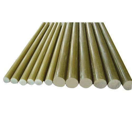
Pultruded fiberglass rods have many benefits over other types of structural rods. They can be fabricated using standard tools and are highly customizable for a variety of applications. These fiberglass rods are lightweight, strong, and offer exceptional corrosion resistance. Because of their versatility, they are more cost effective and can maintain their mechanical properties for up to 15 years. Additionally, custom pultrusion rods are easy to handle and transport, and can be molded to fit specific needs.
Pultruded rods can be used in a variety of applications, including strain insulators, down lead brackets, single and triple standoff brackets, and dead end cross arms. These rods can be molded to your specifications or can be custom-pultruded from fiberglass or carbon fiber cloth. Because they are flexible and durable, they are widely used by manufacturers of construction materials, including automobiles, boats, and aircraft.
Fiberglass rods are manufactured by pultrusion, a process which involves forcing molten glass through ultra-fine holes. Unlike traditional fiberglass rods, which are cut, pultruded rods remain separate during the manufacturing process. The fiberglass rod is then coated with a thermoplastic resin mixture and drawn through a heated die, which then allows it to take the shape it wants. These rods are commonly round, but can be made longer or thinner, depending on their desired application.
Fiberglass rods are versatile and can be pultruded into nearly any shape. They are flexible and can be custom-molded for various applications. Common stock shapes include solid rods, pipes, tubes, bar stock, and channels. Pultruded fiberglass rods can be machined, chamfered, or rounded. And since they are lightweight, they are cost-effective. There are no special tools or machinery needed to manufacture pultruded fiberglass rods.
Another benefit to pultruded fiberglass rods is its durability. Unlike steel, pultruded fiberglass does not rot, rust, or be compromised by invasive pests. In fact, the material is so durable that it can withstand heavy usage. Additionally, it is extremely versatile and durable, making it the perfect choice for outdoor applications where direct contact with weather conditions is inevitable. And because of its lightweight and non-conductive nature, pultruded fiberglass rods are perfect for tool handles.
Another benefit of pultruded fiberglass rods is their low maintenance. Unlike steel, fiberglass rods do not rot, mold, or warp. They are easier to handle and maintain, and do not require expensive coatings. This lowers maintenance and extends the life of the product. This makes pultruded fiberglass rods an excellent choice for many applications, including electrical cable trays. These fiberglass rods are ideal for applications where corrosion resistance is necessary.
The process of pultrusion involves pulling a bundle of glass fibers through a heated die. The result is a fiber-reinforced plastic product. Pultruded fiberglass rods are composed of polyester resin and fiberglass and have many applications. If you're planning to use fiberglass rods in your next project, make sure to contact your local fabricator. In the meantime, here are some great tips for pultruded fiberglass rods. Visit: https://en.wikipedia.org/wiki/Fiberglass for more info on fiberglass.
0 notes
Photo
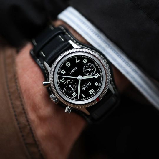
Sturdiness, reliability, and readability. It is according to these three principles that Hanhart manufactures the 417 as the first pilot’s chronograph for the newly founded German armed forces. Hanhart supplied the Bundeswehr with the original model for almost ten years, until the brand shifted its focus to the production of handheld stop-watches from 1963 onwards. The few surviving examples of the historic 417 have since become sought-after vintage chronographs for collectors. After the successful debut of the 417 ES with a 42 mm case almost two years ago, the long-established brand from Gütenbach, situated in the Black Forest, is now focused upon capturing the essence of the watch. The new 417 ES 1954 – with ‘ES’ standing for ‘Edelstahl’ (German for stainless steel) and ‘1954’ noting the model’s very first year of production – marks the return of Hanhart’s most legendary chrono-graph in its historically correct size of 39 mm as part of the official, non-limited collection. In a way, the watch also acts as a time machine, as it combines the style-defining details of the past with contemporary state-of-the-art materials. Particularly refined are the sharp, highly polished chamfers, that mark the transition from the satin-finished lugs to the sides. As a typical Hanhart design element, the fluted bezel rotates smoothly in both directions. Its red position marker is just as reminiscent of the historical model as the details on the dial of the watch. The bi-compax layout and the lettering seem to be the spitting image of the early 417. The numbers, fonts and the logo from the old days have all been revived. To ensure precision and reliability, the chronograph is equipped with the trusty hand-wound calibre SW510 with ‘Swiss Made’ quality. In addition to stop-seconds, it offers a 58-hour power reserve when fully wound. The historic 417 was likewise manually wound, although its range of action outside the cockpit was severely limited due to its low water resistance. The new 417 ES 1954 is water-resistant up to 10 bar. https://www.instagram.com/p/CgkdrmOrdYM/?igshid=NGJjMDIxMWI=
0 notes
Text
Dimensions of different stud bolts with applications
Stud bolts are threaded steel bars generally used for connecting flanges. When these are connected with particular nuts, they work wonderfully in providing toughness and strengthening mechanical joints. Stud bolts are used in almost every industry today like pipeline, drilling, refinery, petrochemical, etc.
What are the types of stud bolts?
Stud bolts help in fastening joints with solid integrity and distributing pressure load. This effectively helps in avoiding damages. Distinguished by their threaded pattern and design, some of the industrial stud bolts are:
Fully threaded stud bolt
Tap end stud bolt
Bonding end stud bolt
Double-end stud bolt
Dowel screw
Weld stud bolt
Clinch stud bolt
What are the sizes of stud bolts?
The size of a stud bolt is measured from either one end to the other or from first thread to first thread. For dimensional tolerance, these points have to be kept in mind for every type of stud bolt:
Commencing from length to 12-inch tolerance = ± 1.6 mm
Starting from Length over 12 inches to 18-inch tolerance = ± 3.2 mm
Initial from Length over 18-inch tolerance = ± 6.4 mm
While measuring the length of the stud bolt, the height of the chamfers is not taken into account.
The dimension of the bolt is shown in metric or imperial units:
Diameter is the measurement of the width of the shank portion of the screw. This does not include the bolt head.
Pitch is the measurement between the tips of the adjoining threads of the shank.
Length is calculated from measuring the end of the chamfer to the undercut of the head, excluding the head itself.
Applications of different stud bolts
Fully threaded stud bolt
This is a long threaded steel bar where nuts are used at both ends for fastening large chunks together. These are even utilized for adjusting parts of machines and for machines that need quick assembling or disassembling. The mentioned metric size for a fully threaded stud bolt is M10 to M100 while its imperial size is 3/8 to 8”. Construction, manufacturing, plumbing, oil extraction, marine, etc. are some of the industrial sectors that use this kind of stud bolt.
Tap end stud bolt
These are shorter stud bolts. The studs are drilled into holes. The design is made in such a way that it contains a shaft as well as a threaded portion to allow a nut to seal the joint. The tap end part has a chamfered point whereas the other end where the nut is fitted might have either a chamfered end or even a round end. These stud bolts are made as per the customised requirement. The metric size is M10 to M100 and the imperial size is 3/8 to 8”
Bonding end stud bolt
The bonding end stud bolt has a broad threaded head with many holes. It helps in bonding solid joints and joining multiple parts with sturdy and immovable integrity. When classic and traditional fasteners are short of supply, these bolts are efficiently utilised. Materials like plastic, carbon fibre, or glass-reinforced plastic products are designed in a complicated fashion. These bonding stud bolts give a tough metal fixation on all these materials.
Double-end stud bolt
This kind of bolt has a uniform threaded length on both its ends and a shaft in the middle portion. This thread accepts nuts for Class 2A tolerances. It is used for high-strength bolting purposes. The metric size of the double end stud bolt is M10 to M100 while the imperial size is 3/8 to 8”. Automobile industries, windmills, turbines, etc. frequently use double-end stud bolts. Moreover, these studs fasten flanges together.
Weld stud bolt
This bolt has a thin head for easy welding into holes. Often used by fabricators, the stud bolts help in fastening tightly to the concerned material from one side. The metric size is M10 to M100 and the imperial size is 3/8 to 8”. This is used for fixation of insulation material and pipes, construction, attach flanges, catering, fixation of burners, in automotive industries, food processing, shipbuilding, electrical industry, etc.
Dowel screw
This screw is designed especially for drilling into wood or metal. The screw is drilled into wood whereas it is fixed in a socket in case of metal. This dowel screw is often used in furniture, flooring, woodworking, or fixing balusters to a staircase. Be it in wood or metal, this screw is installed with a driver tool or locking pliers.
Clinch stud
This stud has a small thin head used in metal notches. It offers high torque resistance.
Conclusion
A torque wrench is used to tighten and loosen studs that are used in every place where more precise torque values are important. This is because studs do not twist when tightening providing a better clamping force. Wherever applicable, the studs give convenient installation and better clamping uniformity.
Content Sources :- ABSGroup
0 notes
Text
In vitro Comparison of Marginal Fit of Cad-Cam Zirconia, SMLS Co-Cr, Pressable Lithium Disilicate, and Cast Ni-Cr Copings - Juniper Publishers
In vitro Comparison of Marginal Fit of Cad-Cam Zirconia, SMLS Co-Cr, Pressable Lithium Disilicate, and Cast Ni-Cr Copings
Authored by Jitendra J Mete
Abstract
Context:Clinically acceptable marginal fit of crowns has been the focus of various investigations. There is limited literature comparing marginal accuracy CAD-CAM zirconia, SMLS Co-Cr, Pressable Lithium Disilicate, and cast Ni-Cr copings.
Aim:Evaluate and compare marginal accuracy of CAD-CAM zirconia, SMLS Co-Cr, Pressable lithium Disilicate, and cast Ni-Cr copings.
Methods and Material: Forty copings were fabricated (Ten each in Group I - CAD- CAM zirconia, Group II - SMLS Co-Cr, Group III - lithium disilicate, and Group IV- cast Ni-Cr copings) on a standardized stainless steel model with long chamfer finish line. Four areas around the tooth surface namely mesial (M), distal (D), buccal (B) and lingual (L) surfaces were digitally analyzed for marginal fit under the stereomicroscope.
Stastical Analysis: Comparison between groups was done by using one-way ANOVA test followed by a Post Hoc Tukey-Kramer multiple comparisons test.
Results: The mean marginal gap (in μm) for Group I on lingual, buccal, mesial and distal surface was 37.05, 38.54, 37.61 and 36.09 respectively. The mean marginal gap (in μm) of Group II on lingual, buccal, mesial and distal surface was 48.48, 50.88, 50.12, and 49.5 respectively. The mean marginal gap (in μm) of Group III on lingual, buccal, mesial and distal surface was 63.04, 64.07, 64.97 and 65.81 respectively. The mean marginal gap (in μm) of Group IV on lingual, buccal, mesial and distal surface was 75.68, 74.75, 73.86, and 72.78 respectively.
Conclusion: The marginal fit of CAD-CAM zirconia copings is more accurate as compared to SMLS Co-Cr, pressable lithium disilicate and cast Ni-Cr alloy copings on a standardized metal model.
Keywords: Marginal Gap; Stereomicroscope; CAD – CAM; Metal Laser Sintering; Pressable Ceramic
Abbreviations: SMLS: Selective Metal Laser Sintering; Co-Cr: Cobalt-Chromium Alloy; CAD: Computer Aided Designing; CAM: Computer Aided Manufacturing; CNC: Computer Numerically Controlled (CNC); HIP: Hot Isostatic Pressing.
Introduction
The success of a dental restoration is determined by 3 main factors: esthetic value, resistance to fracture, and marginal adaptation [1-5]. Inadequate marginal fit leads to cement dissolution, plaque accumulation, which increases the risk of carious lesions & periodontal diseases [6-11].
Traditionally metal copings have been fabricated by the lost wax technique and casting method. Inaccurate marginal fit of copings fabricated by this technique may result from contraction of impression material, distortion of wax patterns, or irregularities in the cast metal. Newly developed selective metal laser sintering (SMLS) technique uses a high power laser to fuse the small particles of metal into a mass that has a desired 3-dimensional shape. The laser selectively fuses powdered material by scanning cross-sections generated from the 3-dimensional digital description of the part (for example, from a CAD file or scan data) on the surface of the powder bed. SMLS is a CAD/CAM based technique in which frameworks and metal copings can be designed and fabricated using cobalt-chromium alloy (Co-Cr). Co-Cr powdered alloy used in this technique has slight variations in composition. The molybdenum content in the alloy powder used in SMLS is comparatively less than the alloy which is used for conventional casting. After each cross section is scanned, the powder bed is lowered by one-layer thickness and a new layer of material is applied on top. The process is repeated until the part is completed. Advantage of SMLS system include easy fabrication of complicated shapes and short working time due to elimination of the procedures of fabricating a wax pattern, investing, burning and casting works [12].
Development in ceramic materials such as lithium disilicate, and zirconium oxide cores, uses of hot press and CAD-CAM equipment have opened up new path for all ceramic restorations [13]. CAD-CAM not only provides reproducible results fulfilling certain standards but also reduces the errors arising from the technicians. However, it is associated with higher cost. When measuring the marginal gap after cementation, the same number of teeth or steel dies as that of restoration sample is needed to control the variables. On the other hand, only one tooth or steel die is needed if the measurement is done without a luting agent. Investigators have found a significant increase in the marginal discrepancy after cementation [14,15]. These results, however, varied according to the luting agent. The marginal fit was, therefore, measured without cementation for variable control in this study.
There is limited literature which compares marginal accuracy of CAD-CAM zirconia, SMLS Co-Cr, Pressable lithium disilicate, and cast Ni-Cr copings. So the present in vitro study was conducted to evaluate and compare the marginal accuracy of CAD-CAM zirconia, SMLS Co-Cr, Pressable lithium disilicate, and cast Ni-Cr copings.
Methods and Material
Fabrication of stainless steel master model
For fabricating a standardized master model, a typhodont mandibular first molar tooth was first scanned using threedimensional (3-D) computer-aided designing (CAD) software. After scanning of the mandibular first molar tooth, a uniform chamfer finish line of 1.2 mm in width, 6-degrees occlusal convergence, 1.5 mm reduction on functional cusps with functional cusp bevel and 1 mm reduction on non-functional cusps simulating a prepared mandibular first molar was carried out on the CAD software. A rectangular platform measuring 4 cm in length, 3 cm in breadth and base of thickness 2 cm made of stainless steel material was chosen for the purpose of milling. To fabricate a standardized master model consisting of a metal die exactly in the centre of the rectangular platform, computer-aided manufacturing (CAM) was carried out using the data obtained from the CAD software which was then transferred to the computer numerically controlled (CNC) milling machine (LAVA CNC 500) and engraving was done. After engraving, finishing and polishing of the master model was carried out. The stainless steel metal master model was used to fabricate all the copings and also to serve as an abutment for the measurement of marginal discrepancy.
Fabrication of CAD-CAM zirconia copings
A dental CAD/CAM system, 3M LAVA CAD/CAM system (3M ESPE Dental Products St. Paul, MN U.S.A) was used to fabricate the 10 zirconia copings used in this study. Metal model of the abutment was scanned using 3M Scanner. Scanned data were then converted into CAD data. Copings for all-ceramic crowns were designed using the dental wings supported by 3M software. No cement space was included for the margin, and 45 μm was used for the axial and occlusal surfaces of the abutment. Thickness of the copings were designed to be 0.5 mm. Design data were converted into processing data and sent to the processing machine (CNC 500 LAVA 3M).The zirconia blocks were cut and milled, and then the milled blocks were finally sintered to make zirconia copings. The internal surfaces & margins of the copings after placing on die were examined using a binocular loupe (HEINE HR-C 2.5x, HEINE, Herrsching, Germany) to check the complete seating.
Fabrication of Pressable lithium disilicate copings
Ten copings were fabricated from lithium disilicate glass ceramics (IPS e.max Press, Ivoclar Vivadent AG) using a combination of the lost-wax and heat-press techniques. Die lubricant (Isocera, Bego, Germany) was applied to the metal die. Wax patterns were fabricated on the dies using dip wax technique to form wax copings. The patterns were contoured parallel to the emergence profile and margins were manually sealed under 1.5×magnification.The thickness of the copings was confirmed with a thickness gauge (POCO 2N; Kroeplin, Schluchtern, Germany) to be 0.5mm. Finally, to re-adapt the margin, the pattern was reflowed completely through the wax over a band approximately 1mm wide with a well heated instrument, PKT No.1. Wax was then added to fill the depression, and when the pattern had cooled, the marginal excess was carved and the margin was burnished. Patterns were invested in phosphate bonded investment (IPS Press VEST Speed, Ivoclar Vivadent AG). After wax elimination glass ceramic ingots (HO 2, Ivoclar Vivadent AG) were plasticized at 9300C and vacuum pressed (EP 500 press furnace, Ivoclar Vivadent AG) into an investment mold. After a holding time of 25 min the pressed crowns were divested, separated and cleaned by applying 1% hydrofluoric acid (IPS e.max Press Invex Liquid, Ivoclar Vivadent AG) for 10 min. Internal surfaces were sandblasted with 100 μm aluminum oxide at 2 bar pressure. The internal surfaces of the copings were examined using a binocular loupe (HEINE HR-C 2.5x, HEINE, Herrsching, Germany) and any visible metal nodules were removed with water cooled diamond bur. To detect the invisible nodules or irregularities, the internal surfaces of the copings was checked on the master dies using vinyl poly-siloxane disclosing paste (Fit checker; GC Corporation). After removing the copings from the die, the contact spot, marked bythe indicator on the inside of the copings was examined visually using a binocular loupe (HEINE HR-C 2.5x, HEINE, Herrsching, Germany), these marked spots were removed until no internal binding was occurred and a uniform thickness of disclosing paste achieved. Finally, the copings were fitted to metal die. All copings were manufactured under supervision by the same dental technician.
Fabrication of cast Ni-Cr alloy copings
For making nickel-chromium (Ni-Cr) alloy copings, wax patterns were fabricated in similar way as for Pressable lithium disilicate copings. The wax patterns were invested with a phosphate-bonded investment (Bellabond Plus, Bego, Germany) and cast with Ni-Cr (Bellasun, Bego, Germany) alloy using an induction casting machine (LC Cast – 60, Confident equipments). After casting, the ring was bench cooled to room temperature and divested. The copings were sandblasted with 50-μm Al2O3 at 0.2- MPa air pressure to remove the investment. The internal surfaces of the copings were examined using a binocular loupe (HEINE HR-C 2.5x, HEINE, Herrsching, Germany) and any visible metal nodules were removed with a tungsten carbide bur (No. H71EF; Brasseler GmbH and Go KG). To detect the invisible nodules or irregularities, the internal surfaces of the copings was checked on the master dies using vinyl poly-siloxane disclosing paste (Fit checker; GC Corporation). After removing the crown from the die, the contact spot, marked by the indicator on the inside of the copings was examined visually using a binocular loupe (HEINE HR-C 2.5x, HEINE, Herrsching, Germany), these marked spots were removed until no internal binding was occurred and a uniform thickness of disclosing paste achieved. Finally, the restorations were fitted to metal die. All copings were manufactured under supervision by the same dental technician.
Every finished coping was placed on the prepared metal die and checked for complete seating after which it is evaluated for the marginal fit accuracy using a stereomicroscope (Wuzhou New Found Instrument Co. Ltd., China, Model Xtl 3400 E). During stereomicroscope evaluation copings were secured to master die model using vice holder. Stereomicroscopic images were analyzed using image analysis system (Chroma Systems Pvt. Ltd. India) and measurements for marginal gap were taken on deepest portion of copings on lingual, buccal, mesial and distal. Total 160 measurements were recorded of 40 copings, 10 of each four study groups. The mean and standard deviation of marginal gap of four Groups on lingual, buccal, mesial and distal surface was calculated. Tukey-Kramer multiple comparison test was applied for comparative evaluation of marginal fit in different groups.
Results
The mean ± SD marginal gap of Group I on lingual, buccal, mesial and distal surface was 37.05 ± 4.19, 38.54 ± 3.68, 37.61 ± 4.05 and 36.09 ± 4.18 respectively. The mean ± SD marginal gap of Group II on lingual, buccal, mesial and distal surface was 48.48 ± 5.99, 50.88 ± 6.0, 50.12 ± 5.91 and 49.5 ± 5.67 respectively. The mean ± SD marginal gap of Group III on lingual, buccal, mesial and distal surface was 63.04 ± 4.21, 64.07 ± 4.26, 64.97 ± 4.41 and 65.81 ± 4.49 respectively. The mean ± SD marginal gap of Group IV on lingual, buccal, mesial and distal surface was 75.68 ± 10.38, 74.75 ± 10.68, 73.86 ± 10.71 and 72.78 ± 10.61 respectively.
Tukey-Kramer multiple comparison tests was applied for comparative evaluation of marginal fit in different groups. The marginal fit of Group I on lingual, buccal, mesial, and distal surfaces as compared to Group II, Group III and Group IV was found to be statistically significant (p<0.001) (Table 1) & (Figures 1-3). The marginal fit of Group II on lingual, buccal, mesial, and distal surfaces as compared to Group III and Group IV was found to be statistically significant (p<0.001).The marginal fit of Group III on lingual, buccal, and mesial surfaces as compared to Group IV was found to be statistically significant (p<0.001).The marginal fit of Group III on distal surface as compared to Group IV was found to be statistically not significant (p>0.05).
Discussion
The ultimate goal of successful fixed partial denture (FPD) prosthesis can be achieved only when an accurate and precise marginal fit is produced. Microleakage and marginal openings are important causes of fixed restoration failures. One of the reasons for high microleakage is the amount of marginal gap, the increase of which causes greater microleakage, because the amount of cement exposed to oral fluids depend on the extent of the marginal gap [16].
Marginal discrepancies in the range of 40-120 μm have been reported to be clinically acceptable with regard to longevity of a restoration [17]. All the copings tested in this study are in the range of 35-80 μm, which is within acceptable limits. The different materials and applied techniques in the manufacturing of crown systems have significant effects on the strength of the final restoration as well as the marginal fit. Imperfect restoration margins offer recesses for adherence of oral bacteria, which may cause secondary caries and traumatic gingival irritation [18]. This in vitro study examined the marginal adaptation of four types of copings, consisting of frameworks fabricated using CAD/CAM zirconia, selective metal laser sintering (SMLS), pressable lithium disilicate and cast nickel-chromium (Ni-Cr) alloy. The marginal discrepancies of group CAD/CAM zirconia were significantly smaller compared to those of the other three study groups.
A stainless steel die was used for making copings and served as the abutment for the measurement of marginal discrepancy for all the copings made in this study. The advantages of the stainless steel die are standardized preparation and avoidance of wear of the die during the coping fabrication and measurements. The deep chamfer finish line preparation was selected because it meets the requirements for all the four study groups used in this study [19]. The majority of marginal discrepancy is known to develop during the oxidation cycle for metal copings [20]. This is often attributed to the release of residual stresses incurred during casting, grinding or polishing phases of the procedure. As the prostheses cools from the firing temperature, the difference in thermal contraction between the metal coping and the porcelain may result in additional marginal discrepancy [21].
The mean marginal gap widths of the CAD/CAM zirconia fabricated superstructures were significantly smaller than those of the selective metal laser sintered frameworks. This finding can be attributed to advancements in scanning technology, restorationdesigning software with improved margin detection and precision milling technologies. The vertical marginal gap values obtained were within the range of clinical acceptance i.e. 40 μm to 120 μm. The CAD/CAM zirconia system mills the framework with the final dimensions out of a densely sintered Y-TZP (Yittria stabilized Tetragonal Zirconia Polycrystals) blank which is fabricated with the ‘Hot Isostatic Pressing (HIP)’ technology. This technology involves sintering partially sintered zirconia material at a high temperature in a high density, homogenous zirconia material with improved mechanical properties [22]. For CAD/CAM ceramic crowns, marginal gaps of 17 μm to 118 μm have been reported by various authors [23]. Similar results were obtained in the present study.
However, a higher accuracy was achieved with the soft, partially sintered Y-TZP ceramics compared with the hot isostatic pressed (HIP) Y-TZP blocks. This finding can be attributed to the ease of machining and the precisely controlled sintering cycle in a specially designed sintering oven which aided in achieving a consistently accurate fit. The lesser accuracy of hard HIP-YTZP ceramics can be attributed to their extreme hardness and higher flexural strength (> 1,200 MPa), which can cause greater wear of the milling burs and a reduction in the efficiency of the milling unit consequently leading to lesser accuracy of fit. The Post Hoc comparison of both hard and soft types of ceramics showed no statistical significance, indicating that either form of Y-TZP ceramic produces clinically acceptable restorations. The comparable mechanical properties and the relative ease and speed of soft Y-TZP blank milling may explain why more operators choose this method to fabricate zirconia restorations, whereas only a small number prefer the hard Y-TZP blanks [24].
The results of the present study suggest that the new zirconia ceramic systems fabricated with CAD/CAM technology presents better marginal fit as compared to selective metal laser sintered copings. These results were in accordance with a study conducted by Ece Tamac et al. [25]. The results of this study shows that selective metal laser sintered copings shows better marginal fit than pressable lithium disilicate and cast Ni-Cr alloy copings. This finding can be attributed to the fact that additive manufacturing is used during selective metal laser sintered copings fabrication and this technique uses a high power laser to fuse small particles of metal into a mass that has a desired 3-dimensional shape. The laser selectively fuses powdered material by scanning crosssections generated from a 3-dimensional digital description of the part (for example from a CAD file or scan data) on the surface of a powder bed. After each cross-section is scanned, the powder bed is lowered by one-layer thickness, a new layer of material is applied on top and the process is repeated until the part is completed. These results are in accordance with Montero J. et al who concluded that selective metal laser sintering may be an alternative to vacuum-casting of base metals to obtain passivefitting implant-supported crown copings [26].
Glass-ceramics have superior stability, biocompatibility, esthetics, and chemical inertness, making them a viable alternative restorative material. Leucite-reinforced glass-ceramics were originally designed for CAD/CAM restorations because of their high durability and ability to be milled accurately. These ceramics are reinforced by the incorporation of leucite crystals into their structure, giving them improved toughness and strength [27]. In the present study, the leucite-reinforced glass-ceramic superstructures showed higher accuracy of marginal fit compared with the cast Ni-Cr superstructures.
IPS Empress Copings show less marginal gap than the conventionally casted Ni-Cr alloy copings. IPS Empress 2 (Ivoclar Vivadent, Schaan, Liechtenstein) is a lithium-disilicate glass ceramic (SiO2-Li2O) that is fabricated through a combination of the lost-wax and heat-pressed techniques. A glass-ceramic ingot of the desired shade is plasticized at 920°C and pressed into an investment mold under vacuum and pressure. Its predecessor, IPS Empress (Ivoclar Vivadent) is a leucite-reinforced glass ceramic (SiO2-Al2O3-K2O) which, due to its strength is limited in use to single unit complete-coverage restorations in the anterior segment. IPS Empress 2 has improved flexural strength by a factor of 3 over IPS Empress, can be used for 3-unit fixed partial dentures in the anterior area and can extend to the second premolar. The framework is veneered with fluoroapatite-based veneering porcelain (IPS Eris; Ivoclar Vivadent), resulting in a semi translucent restoration with enhanced light transmission. IPS e.max press (Ivoclar Vivadent) was introduced in 2005 as an improved press-ceramic material compared to IPS Empress 2. It also consists of a lithium-disilicate pressed glass ceramic, but its physical properties and translucency are improved through a different firing process [28]. Yeo IS et al. [29] concluded that the IPS Empress 2 systems showed the smallest and most homogeneous gap dimension, whereas the conventional In-Ceram system presented the largest and more variable gap dimensions compared with the metal ceramic restorations.
The conventionally casted Ni-Cr superstructures show more marginal gap when compared with the CAD/CAM superstructures. This finding can be attributed to the expansion and contraction associated with the impression materials, gypsum, wax pattern distortion during removal and the spruing process are other factors that may affect the accuracy of superstructures fabricated using the lost-wax process [30]. These results are in accordance with a study conducted by Tamer E. Shokry et al. [31] who concluded that titanium copings fabricated by CAD/CAM demonstrated the least marginal discrepancy among all groups, while the base metal (Ni-Cr) groups exhibited the most discrepancy of all groups tested.
It is difficult to interpret the statistical results of the previous studies because of variations in sample size, the measurement per specimen and the measurement methods used. There is no standardized method to measure the marginal fit. The most common methods are ��direct viewing, sectioning, probing and explorative and visual examinations’ [32]. In the current study, the direct viewing of the crown on a die is used to measure the marginal fit of all the copings. Direct viewing has the advantage of being nondestructive and therefore applicable to clinical practice. The vertical cervical marginal gap measurement was selected as the most frequently used to quantify the accuracy of fit of a restoration [33].
Conclusion
Within the limitations of the present study, following conclusions can be drawn:
The marginal fit of CAD/CAM zirconia copings is more accurate as compared to selective metal laser sintered (SMLS), pressable lithium disilicate and cast Ni-Cr alloy copings on a standardized metal master model.
Base metal alloy (Ni-Cr) exhibited a discrepancy that was significantly higher than the rest of the groups.
The marginal discrepancies of all the copings were within the clinically acceptable range of 80-120 μm.
For more Open Access Journals in Juniper Publishers please click on: https://juniperpublishers.com
For more articles in Open Access Journal of Dentistry & Oral Health please click on: https://juniperpublishers.com/adoh/classification.php
To know more about Peer Review Journal of Dentistry & Oral Health
1 note
·
View note
Text
What Is Wire Forming?
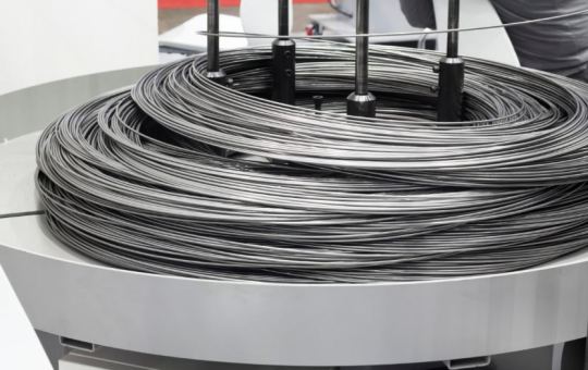
Wire forming is a method for applying force to change the contour of wire by bending, swaging, piercing, chamfering, shearing, or other techniques. The various techniques for wire forming can produce any type of shape, form, or configuration. The process starts with coiled wire that is straightened before being formed.
Common metals used for wire forming include steel, brass, stainless steel, copper, aluminum, and a variety of different alloys. The diameters of wires vary from 0.5 mm to 6.5 mm, or 1/64th of an inch to a quarter inch and can produce 2 and 3 dimensional wire forms.
The types of equipment to complete wire forming vary between manual crafting to advanced CNC programmable machines. The process includes options for coating and protecting final products for use in harsh conditions.
Methods Used for Wire Forming
Though there are several types of equipment used to perform wire forming, in most cases, wire roof guard
machines are manually or automatically operated. Manual machines include ones that are operated by manual force and ones that are electronic but manually loaded. Automatic machines have advanced computer numerically controlled (CNC) programming and complete production without manual involvement.
Methods For Wire Forming
Wire forming is performed using several different processes each designed to achieve a different shape, pattern, or configuration. The methods of wire forming are used for other part production but have been adjusted for wire forming.
Manual Wire Forming:
The oldest method for wire forming is manually operated machines, which involves a hand lever and spindle. Manual machines can be drawn or rotary die and have gears that increase the applied bending force.
Coil Wire Forming:
Coil, or spring wire forming, involves winding wire around a metal blank. It is also used for the manufacture of electrical coils where a conductive wire is evenly wound around a ferromagnetic core. Coil winding takes different forms depending on the final product. Electrical coils have to be more precisely wound than springs and can require more than one winding.
Roll Wire Forming:
Roll forming is a cost efficient method for the production of flat, round, and other shapes of wire parts. The process can manufacture undercuts, knurls, pointing, chamfers, grooves, surface finishes, collars, and threads. Roll formed wire parts have extra strength after being hardened, having rounded edges, and being prefinishing.
Bend Wire Forming:
In the wire bending process, wire can be shaped into unlimited configurations to fit any application. Diameters of 0.4 mm to 16 mm, or 0.016 in to 0.625 in, can be easily formed. Since the bend in the wire is made prior to the wire being cut, the process has no scrap or waste and does not need secondary finishing.
CNC Wire Bending:
CNC wire bending machines can be pneumatic or hydraulic for efficient and rapid production. They can bend and shape rebar to 180o using single or double wire. The machine straightens the bar prior to the bending process. CNC machines have exceptional accuracy and cut wire to the exact required dimensions. The types of wire a CNC machine can be programmed to shape includes music, hard drawn, basic or coated metals, 300 series stainless steel, brass, and beryllium copper. Wire diameters vary between 0.008 in to 0.250 in or 0.0203 mm to 6.35 mm.
0 notes
Text
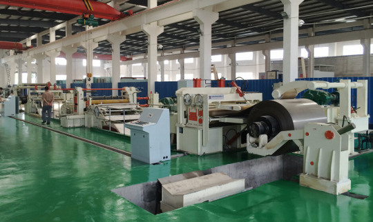
Reasons for the uneven coiling of the slitting line
Uneven coiling caused by insufficient tension: If the tension is weak at the beginning of the coiling, it is prone to misalignment at the end of the coiling. Therefore, the tension is increased at the beginning, and the larger the roll, the smaller the tension. The operation method can effectively prevent the occurrence of misalignment.
Dislocation caused by unbalanced coiling tension: poor straight angle when the coil head is cut, bad straight angle when occluding, incorrect width setting of the uncoiler after the plate is passed, and the steel plate is sent out after the slitting machine is cut and the steel plate is sent out for comparison. The length of the two sides of the steel coil will be different during the big movement. The short side is easy to produce tension changes. Therefore, when winding the steel coil on the expansion and contraction drum of the winder, it is best to confirm that the entire width direction of the steel coil is accurate, and it is tightly attached to the expansion and contraction drum, and then the coiling can be started.
Dislocation caused by poor bite position of the jaws in the expansion and contraction drum of the winder: When the position of the knife, the middle divider, and the bite positions in the jaws of the expansion and contraction drum of the winder are inconsistent, the change of the left and right tension of the steel coil will cause the coiling misalignment.
Coiling dislocation caused by the left and right swing of the steel belt in the looper: The left and right swing of the steel belt in the looper will cause the angle of entering the tension device to change, which will cause the winding dislocation. Use felt and other soft materials to press on the steel belt to prevent the steel belt from swinging.
Coiling misalignment caused by production line stoppage: When the production line is stopped and started, when the tension between the tension device and the winder is reduced, the contact pressure between the steel strips will be reduced, and lateral misalignment is likely to occur, which will cause coiling misalignment. Flexible use of winders and dividers can effectively prevent winding misalignment.
Rolling misalignment caused by poor divider width setting: The general divider width setting is the width of the finished product plus the thickness of the board. If it is too wide, the steel plate will move left and right, and the coiling will be misaligned.
Wuxi Bangzhou Machinery Manufacturing Co., Ltd. is a company specialized in steel coil straightening machine, slitting line, cut to length line and flat bar straightening and chamfering machine. Our company is a professional slitting machine manufacturer. If you are interested in slitting machines, don’t hesitate to contact with us.
0 notes
Text
Choosing the Right Chamfer Steel Bar Manufacturer for Precision and Quality
In manufacturing, where precision and quality are non-negotiable, every component plays a crucial role in shaping the final product. Chamfer steel bars stand out as unsung heroes, contributing to the structural integrity and functionality of countless applications.
Choosing the proper chamfer steel bar manufacturer is a pivotal decision that can make or break the success of your project. In this blog, we embark on a journey to explore the nuances of selecting the perfect partner for your chamfer steel bar needs.
Understanding the Essence of Chamfer Steel Bars
Before delving into choosing the proper chamfer steel bar manufacturer, it's essential to grasp the significance of chamfer steel bars. These specialized components serve as connectors, strengthening and stabilizing various structures. The chamfered edges, meticulously crafted by skilled manufacturers, facilitate easy insertion and alignment during assembly.
The Art of Precision Manufacturing
Precision is the heartbeat of manufacturing, and chamfer steel bars are no exception. A reputable chamfer steel bar manufacturer understands the criticality of precision in every step of the production process. Each phase demands meticulous attention to detail, from the selection of raw materials to the final chamfering process.
Key Considerations When Choosing a Chamfer Steel Bar Manufacturer
● Chamfer Steel Bar Manufacturer - Expertise and Experience:
Selecting a chamfer steel bar manufacturer with a proven track record in chamfer steel bar production is paramount. Look for a company with years of experience and a portfolio of successful projects. Seasoned manufacturers are more likely to possess the knowledge and expertise to meet your requirements.
● Chamfer Steel Bar Manufacturer - Quality Control Measures:
Quality is non-negotiable when it comes to chamfer steel bars. Inquire about the quality control measures implemented by the chamfer steel bar manufacturer. A reliable company will have stringent quality checks at every stage of the manufacturing process, ensuring that each chamfer steel bar meets the highest standards.
● Chamfer Steel Bar Manufacturer - Customization Capabilities:
Every project has unique specifications, and your chosen manufacturer should have the flexibility to accommodate customization. Whether it's a specific size, shape, or coating requirement, opt for a chamfer steel bar manufacturer capable of tailoring their products to suit your project's needs.
● Chamfer Steel Bar Manufacturer - Material Selection:
The quality of chamfer steel bars is inherently linked to the materials used in their production. A reputable chamfer steel bar manufacturer will transparently communicate the type and grade of steel employed, assuring you of the durability and performance of the final product.
● Chamfer Steel Bar Manufacturer - Communication and Collaboration:
Effective communication is the cornerstone of a successful partnership. Choose a chamfer steel bar manufacturer that values collaboration and keeps you informed at every stage of the production process. A transparent and communicative manufacturer ensures that your expectations are met and exceeded.
● Chamfer Steel Bar Manufacturer - Sustainable Practices:
In an era where sustainability is a global priority, consider the environmental practices of your chosen manufacturer. Opt for a chamfer steel bar manufacturer that embraces sustainable and eco-friendly manufacturing processes. This aligns with ethical standards and reflects a commitment to a greener future.
● Chamfer Steel Bar Manufacturer - On-Time Delivery:
On-time delivery is crucial in the fast-paced world of manufacturing. Delays can have a cascading effect on your project timelines. Assess the chamfer steel bar manufacturer’s track record in meeting delivery schedules and inquire about their processes for handling unforeseen challenges during production.
The Journey to Excellence
Choosing the proper chamfer steel bar manufacturer encompasses a holistic approach beyond technical specifications. It involves building a relationship based on trust, reliability, and shared values. As you consider manufacturers, evaluate their commitment to open communication, sustainability, and punctual deliveries.
The End Note
The decision-making process can be a daunting task. However, armed with the knowledge of critical considerations such as expertise, quality control, customization, material selection, communication, sustainability, and on-time delivery, you are better equipped to make an informed choice.
As we conclude this exploration, one name continues to resonate – Matta Drawing Works. Renowned for its precision, commitment to quality, and a legacy of excellence, Matta Drawing Works emerges not just as a chamfer steel bar manufacturer but as a partner in your journey toward manufacturing success. Choose the path of excellence; choose the reliability of Matta Drawing Works.
0 notes
Text
Pipe Fittings
This chapter presents various types of pipe fittings. Of all the fittings, the elbow is the one most often used. Simply put, the elbow, or ell, is used when a pipe changes direction. Elbows can turn up, down, left, right, or any angle in between. When one finds it necessary to draw a 90° elbow or calculate how much space it will occupy in a routing configuration, knowing its length becomes essential. An elbow's length is commonly referred to as the center-to-end dimension and is measured from the centerpoint of its radius to the end of either opening. Dimensional sizes of fittings are typically provided by the manufacturer of the fitting. Manufacturers issue dimensioning charts containing lengths for a particular fitting. Another elbow that may be used under certain circumstances and with permission from the customer is the 90° short-radius elbow. The 90° short-radius ell makes a much sharper turn than does the long-radius ell.
Emissions from Pipe Fittings and Gaskets
Threaded pipe fittings in the seal flush line can be significant leak sources, with readings above 1,000 ppm.4,17 Similar emission levels may be measured near the gasket region on the seal chamber face. Any leakage from these areas may drift into the emission measurement area for the mechanical seal. The mechanical seal may then be erroneously implicated as a leaker. It should be standard practice to sniff nearby hydraulic fittings and the flange gasket area if excessive VOC concentrations are detected adjacent to the mechanical seal.
Leak-tight threaded pipe fittings can be more easily attained using anaerobic paste-type sealants rather than PTFE tape. The seal chamber face must be smooth to be emission tight. Gaskets and O-rings must be free of nicks and scratches.
32.16.2 Thermoplastic Fittings Manufacturing
Thermoplastic pipe fittings may be injection-molded, fabricated, rotomolded, or thermoformed. Injection-molded fittings are generally made in sizes through 12-in. nominal diameter. Typical molded fittings are tees, 45-degree and 90-degree elbows, reducers, couplings, caps, flange adapters, stub ends, branch saddles, service saddles, and self-tapping saddle tees. Electrofusion couplings and fittings are either made by injection molding or machined from pipe stock. Electrofusion fittings and couplings are made with a coil-like integral heating element incorporated into the fitting. Joining with other fittings uses an electrical fusion device that provides electricity into the heating element, which melts the adjacent thermoplastic material and creates a fusion-welded joint.
Larger-diameter fittings exceed the capabilities of injection molding and are typically fabricated. Rotomolding is used for the manufacture of polyethylene large-diameter (up to 60 in.) and custom fittings for polyethylene corrugated drainage piping applications.
Thermoformed fittings are made by heating a section of pipe and then using a forming tool to reshape the heated area. Examples of thermoformed fittings are sweep elbows, swaged reducers, and forged stub ends. Some polyethylene corrugated pipe fittings and appurtenances are also thermoformed.
All proprietary joints shall be made in accordance with the manufacturer’s instructions. Care shall be taken to establish satisfactory jointing techniques for all water service pipework. When making joints by welding, brazing, or soldering, precautions shall be taken to avoid the risk of fire. All burrs shall be removed from the ends of pipes and any jointing materials used shall be prevented from entering the waterways. All piping and fittings shall be cleaned internally and free from particles of sand, soil, metal filings, and chips, etc.
8.19.3 Cast iron pipes
Flexible mechanical joints shall be made in accordance with the manufacturer’s instructions.
For molten lead joints, the spigot and socket shall be centered with rings of dry yarn caulked tightly into the bottom of the spigot to prevent the entry of lead into the bore of the pipe and to prevent contact of lead with the water.
Synthetic yarns that do not promote the growth of bacteria shall be used to prevent contamination of the water. The remainder of the joint space shall be filled with molten lead (taking care that no dross enters the joint), cold wire, strip, or spun lead (lead wool). The joint shall be caulked to a smooth finish with pneumatic tools or a hand hammer of mass not less than 1.5 kg. When working with spun lead, caulking tools shall be of a thickness to fill the joint space, ensuring thorough consolidation of the material to the full depth of the socket.
Lead joints shall be finished about 3 mm inside the face of the socket.
Flange joints shall be made with screwed or cast on flanges.
8.19.4 Steel pipes
Welded joints shall not be used where a protective lining would be damaged by heat, or where the pipework is employed as a primary circulation to an indirect hot water heating system.
Screwed joints in steel piping shall be made with screwed socket joints using wrought iron, steel, or malleable double crimping fitting. A thread filler shall be used. Exposed threads left after jointing shall be painted or, where installed underground, thickly coated with bituminous or other suitable corrosion preventative agent.
Flange joints shall be made with screwed or welded flanges of steel or cast iron using jointing rings and, if necessary, a suitable jointing paste. The nuts shall be carefully tightened, in opposite pairs, until the jointing ring is sufficiently compressed between the flanges for a watertight joint.
8.19.5 Unplasticized PVC pipes
8.19.5.1 Mechanical joints
Mechanical joints in unplasticized PVC piping of sizes 2 and upwards shall be made in accordance with BS4346: Part 2, by the use of push-fit integral elastomeric sealing rings which are compressed when the plain ended pipes are inserted into the adjoining sockets. The plain pipe ends shall be chamfered and the surfaces cleaned and lubricated.
The chamfered pipe end shall be inserted fully into the adjoining socket (except where provision is to be made for expansion), or as far as any locating mark put on the spigot end by the manufacturer. The sealing rings shall comply with BS2494.
8.19.5.2 Compression joints
Compression joints shall only be used with unplasticized PVC piping of size 2 and smaller. The joints shall be of the nonmanipulative type. Care shall be taken to avoid overtightening.
8.19.5.3 Solvent cement welded joints
Solvent cement welded joints in unplasticized PVC piping shall be made using solvent cement complying with BS4346: Part 3 recommended by the manufacturer of the pipe. The dimensions of the spigots and sockets shall comply with BSEN1452: Part 1–5.
Joints may also be made using integral sockets formed in the pipes and solvent cemented.
8.19.5.4 Flanged joints
Flanged joints used for connections to valves and fittings shall use full-face flanges or stub flanges, both with corrosion resistant or immune backing rings and bolting.
8.19.5.5 Polyethylene pipes
Mechanical joints shall be either plastics or metal proprietary compression fittings, for example, brass, gunmetal, or malleable iron. These shall include insert liners to support the bore of the pipe except where the manufacturer of the fitting instructs otherwise.
To ensure satisfactory jointing of the materials from which the pipe and transition elbow are made compatibility shall be established. The manufacturer’s instructions shall be carefully followed.
No attempt shall be made to joint polyethylene piping by solvent cement welding.
Large pipe fittings and valve components must be press forged and will require extensive machining. Whereas small parts such as the flange previously described can be quickly heated and cooled, and given optimum process conditions, should exhibit microstructure and properties similar to pipe and tube, the properties of large forgings will be location and thickness dependent. While no large forged part has yet been made from 740H, the properties of a solution-annealed, water-quenched and aged 343-mm-diameter bar shown in Table 14.2 are informative. Yield strength near the surface is comparable to that of thin wall tube, but yield strength at the bar center, while meeting ASME minimum, is significantly lower. Ductility and toughness were good. A hardness traverse taken on the as quenched bar showed VHN 170 at the surface and VHN 290 at the center. This is indicative of strong auto-aging in the bar center. Because the γ′ that forms on slow cooling is relatively coarse, after the final aging treatment, the bar center will have lower strength than the surface. The microstructure and creep strength at the center of the bar has not been evaluated.
A calculated continuous cooling transformation diagram for alloy 740H is shown in Fig. 14.26. This diagram supports the notion that significant γ′ hardening will occur even during water quenching of a large forging. A cooling simulation was conducted for the bar heat treatment using DEFORM software [49]. The cooling rate at a depth of 25 mm was 315°C/min and at the bar center was 30°C/min. Based on the calculated CCT diagram, there should be about 10% γ′ in the center and no γ′ at the surface. That is consistent with the experimental results.
Filament-wound pipe fittings, such as elbows and tees have been used in the chemical, and oil industry since the 1980s.9 Traditionally, composite pipe fittings were produced manually or semi-manually, but the development of CNC winders with six or more axes has allowed automated production of pipe fittings since the 1990s. The efficiency of these advanced machines depends on methods and software to determine winding patterns and perform fabrication of the complex shape within manufacturing specifications. Winding pattern generation is particularly challenging since a substantial amount of data storage/processing is required to meet manufacturing requirements (e.g., fiber tension and full-coverage) of non-axisymmetric patterns, which are required for filament-wound elbows or tees.72 On the other hand, it is worth noting that CAM software capability, rather than hardware, is considered the limiting factor for improving the performance of automated winders of non-axisymmetric parts. Consequently, general-purpose filament winding systems for pipe fittings are currently deemed impractical due to the lack of universal mathematical models and design software for CAM.9,73 Although some progress has been made to determine closed-form solutions for efficient winding patterns on specific shapes, such as elbows,74,75 most CAM systems still implement approximate methods to design and produce specific pipe fitting geometries.73 An illustration of a software-generated winding pattern, and the resulting wound elbow, is included in Fig. 11.75
Leaking valves and pipe fittings are the next concern when pressure is dropping during a test. Test sections should be isolated at pipeline block valves by using slip blinds to insure no leakage. If the test section cannot be blinded but the valves are double blocked instead, the operator must measure pressure increase in the adjacent section between the double-blocked valves to insure a tight seal exists. You need to be careful when using a thin “fire blind” at an isolation valve because under pressure the thin blind will deform and the blind cannot be removed without removing the entire valve. This often requires calling in vacuum trucks to remove product on the opposite side of the test valve being removed.
So, leakage through valves and fittings jeopardizes the chances for a successful test and may lead to data that cannot be correlated, and in that situation, the pipeline must be retested.
Tree piping is defined as all pipe, fittings, or pressure conduits, excluding valves and chokes, from the vertical bores of the tree to the flowline connections. The piping may be used for production, pigging, monitoring, injection, servicing, or testing of the subsea tree. Inboard tree piping is upstream of the first tree wing valves. Outboard tree piping is downstream of the first tree wing valve and upstream of the flowline connector.
Tree piping is normally designed in accordance with ASME B31.3. The guidelines in the API specifications are general and, in many cases, open to interpretation. It is up to the manufacturer to apply his engineering judgment.
0 notes
Text
Understand metal fabrication Before You Regret.
The enhancement of this brand-new CNC transforming facility with Multi-Tasking capacity combines advanced modern technology, productivity and also worth to provide exceptional performance. As an (MY) configuration, the maker showcases milling capacity and Y-axis performance together with a standard through-hole chuck package, and integral transforming pin electric motor to process a variety of components in a solitary arrangement. The enhancement of this new CNC lathe will certainly assist in allowing Prototek to manufacture parts rapidly as well as effectively! Whether in your balcony, stairway situation verandahs or balcony, you could quickly set up one such balustrade. No issue exactly what the layout and also colour code of your home is, a stainless steel balustrade would match every solitary style! RINOX Engineering - Asia's greatest factory creating Stainless Steel Handrail and also Glass Hardware. RINOX products are offered in even more than 65 countries throughout the world. This remark has been gotten rid of by the writer. This comment has been gotten rid of by the writer. Subscribe to our newsletter to obtain the most recent updates to your inbox. Your e-mail address is secure with us! July (10) How to Buy Authentic Sprinter Parts? Servicing your lorry is not needed legally, but there are multiple reasons to do so often.
Straight Bits: These tools reduced on both the end of the tool and on the sides. There are many variants of the geometry of these bits. A lot of the product listed below is committed to clarifying the differences and also their usage. Ball-End Bits: These bits have a round account at the tip. This enables them to reduce 3D surfaces. Chamfer and also Engraver Bits: These cutters involve a point at the idea. The most effective part is that they use sheet steel manufacture and laser cutting service, all under one roof. So, those who require these two services will definitely discover such firm handy. The company should meet all your sheet steel fabrication as well as laser cutting needs with utmost effectiveness and perfection. They have actually experienced and also effective specialists to provide service. They provide excellent engineered option to all the laser cutting as well as sheet metal manufacture issues. Prints have a border around the entire print that include letters as well as numbers as revealed in the above print between the red lines. These numbers as well as letters are used like a map in order to help situate as well as determine specific locations of a print. The letters remain in alphabetical order from the base up. The numbers are in mathematical order from right to left. Consequently, you are to read the zones from right to left.
As with any type of market, the longer a business has stayed in business, the more probable it is that they do great and also supply outstanding consumer solution. More recent firms are not always a poorer option, but a steel stamping business that isn't really offering good solution and top quality items won't last long. When you're looking for the best die manufacturer or metal stamper for your needs, search for companies that have stayed in business for a minimum of five to ten years.
This will develop even more jobs for U.S.
With these new markets opening up, U.S. China might slow in the future as they fight with their own inner facilities as well as national debt scenarios. China's short-term issues are foreseeable and also as the worldwide economic climate relocates far from underwriting development, these problems will certainly come to be extra obvious. This will develop more work for U.S. U.S. for replacement manufacturing. Additionally, relying on just how they begin to check out the influences their manufacturers are bring upon on the environment from their low-cost, careless approach to production, contracting out to China can be extra pricey if they choose to enforce more stringent environmental laws.
Requirements could consist of load-bearing capability, sorts of forms, alloys and sizes. Steel light beams, bars as well as plates have actually to be assembled in particular methods to produce some distinct structural components such as girders and trusses. The commercial applications of creating metal parts and structures are far and also wide. They cover both small building as well as massive building tasks. Several of the structures and parts that have to be fabricated are extremely specialized that they should comply with specs that are special to a specific project. Log in or Create Account to upload a comment. Author: Carla Bruni Metal making devices are used as a vital dimension of the manufacturing market. It is used in the structural steel sector as well as it helps in various other steel fabricating markets. Customers of the manufacturer of steel producing equipment array from average and also tiny sized enterprises to iron and fabricating shops and huge building business. Author: Robert Henson Metal producers collaborate with a selection of metal kinds, consisting of steel. One of the most intriguing aspects of the steel manufacture business is that there are lots of areas that an individual can focus on.
Toolmaking for metal stamping
4/4, 5/4, 6/4, 8/4, 12/4, 16/4
Robotic Welding
Version A Formed Part For Most Parts
Personalized steel cornice trim
Closing down when Finished
Publisher: Robertcorin Roof substitute is just one of the vital maintenance jobs of residence. Over the period, the top quality of roofing obtains shabby as well as it requires substitute. Author: Will Peartin When home owners choose roofing products, they take into consideration toughness as one of the most vital elements. You could additionally look at region, cost, and also your personal choice in determining what to obtain. Author: Francis Murphy When you desire to replace the roof of your residence then the most difficult decision is to make a decision the sort of roofing you are mosting likely to have. her comment is here Recently Astro Engineering was gotten in touch with for a large order of laser and developed components that had to be delivered in a limited period. The consumer provided the prints for the work which was composed of virtually 8000 parts constructed from 16 gauge mild steel. There were 8 different components needed, with amounts ranging from 40 to 2000 parts of each. For this huge laser job, the auto load/unload system on the laser was well made use of. Several press brakes were used to complete all the developing. Whatever is split independently for a simpler time designating toolpaths in the toolpath arrangement software program - Mastercam. Each part is exported to a different data if you like. Data concerning the table is stored in the Rhino data as notes. Right here you could see limit dimensions, board feet needed, as well as the dimension of the needed block of timber for each and every item. The model table was made from a single item of 16/4 Yellow Poplar. The board was 4" thick, 10" vast as well as 16' long.
Components are welded with each other, and afterwards after cooling down the machine or structure is usually sand blasted and painted. This end product is thoroughly checked prior to it is delivered off to the client. Several metal fabricators focus on particular procedures based upon their clients' demands and also their very own expertise. These might be punching, welding, forging, spreading, brazing, shearing, drawing and spinning. Also greater degrees of specialization consist of electrical as well as hydraulics solutions. Do not miss the current information! Receive industry as well as products information from the market classifications that matter to you most. Keeping up to date on market information as well as trends, product statements and also the most recent advancements. Characteristic Metals is honored to announce we passed our yearly NADCAP Welding security audit. We are really happy of our team on this achievement and anticipate offering our fabrication and welding services to give a winning service to our existing or a new prospective consumer. Hallmark Metals would love to want you all an extremely Happy and also Safe Holiday Season! Trademark Metals wish to say thanks to all the service guys as well as women who fight for our liberty.
Please permit us the possibility to quote on your Sheet Metal and also Machining requirements. We waiting to teaming with you as well as getting your components going for our center in the new future. Hallmark Metals is delighted to introduce we have upgraded our CNC Turret Press to a much extra power as well as expense effective machine that is currently up and running. Our consumers will certainly experience better cost via this while our environmental influence is lowered too. And also you'll require to collaborate with architects, specialists and also other building employees to bring styles to life. You'll desire to check about and also see what kind of openings there are if you're interested in the sheet metal area. The good news is, that procedure is easier than ever with making use of on the internet task sites, where there are any kind of variety of ads for different tasks. Have a look at just what these websites need to use as well as you're virtually guaranteed to discover something that suits your demands.
1 note
·
View note
Text
Influence of Wiper and Conventional Inserts at Profile Geometry During Turning of D2 Tool Steel - Juniper Publishers
Juniper Publishers - Open Access Journal of Engineering Technology

Abstract
Latest inventions in the field of manufacturing drive the new technologies and different sources of production and to design the various sources to enhance the productivity as well as to reduce the cost, while maintaining the required specifications and high standards of the products. For achieving the production with high quality, tool manufacturers are continuously improving cutting edge, coating, geometry and the material of the tool. The tool geometry affects different aspects of tool like cutting temperature, tool wear and tool life, surface roughness, dimensional accuracy and surface integrity in the machining. The existing study is an attempt to explore the effect of wiper and conventional insets at profile turning. In this research inserts (wiper and conventional) having three different tool of nose radius (0.4, 0.8 and 1.2mm respectively) were evaluated at cutting speed (150m/min), feed rate levels (0.05. 0.10, 0.15, 0.20mm/rev), and depth of cut (0.2mm). Workpiece surface roughness (Ra) dimensional accuracy and microhardness of the machined surface were assessed. It was found that in profile turning in case of conventional inserts with larger nose radius of 1.2mm performed better than the other two inserts in term of surface roughness and dimensional accuracy. While in case of wiper inserts surface roughness and dimensional accuracy results were not better as comparing to conventional inserts. Microhardness under the machined surface was increased in both the cases of wiper and conventional.
Keywords: Profile turning; D2 tool steel; Inserts (Wiper and Conventional); Dimensional Accuracy; Surface roughness; Microhardness
Introduction
Hard part turning which is also known as hard turning (HT) is the machining of material having hardness more than 60 HRC, these types of materials are cut with CBN and Ceramics tools [1]. In the hard turning process, not only operating parameters and geometry of tool are important but also the material composition and tool type are the elements that influence the surface finish of the product. Previous literature indicates that, in order to increase efficiency in terms of tool life, surface roughness, tool geometry and surface integrity are the parameters that are to be considered [2]. The wiper technology for turning is made up of series of radii that form the cutting edge. In wiper insert adjacent to nose radius, 3 to 9 smaller radii were introduced [3]. To ensure a better surface finish, operating parameters are important and selected very carefully [4], tool geometry and material [5], and surface reliability is very essential for the machined components having elevated thermal and mechanical stresses [6]. Authors conducted an experimental study while machining D2 tool steel with wiper inserts and found that feed rate is the major factor that affects the surface roughness. Further in depth analysis of surface integrity microhardness was extended up to 150μm beneath the machined surface, and no white layer formation was found after machining [7]. Denni Kurniawan et al. used wiper inserts for the metal removal process of martensitic stainless steel at different material removal speeds and feed rate, and found that combination of truncated feed rate and speed generated the higher tool life with better surface finish [8]. D.M. D’Addona & Sunil J. Raykar carried an experimental research to find out the effect of wiper and conventional inserts during turning of oil hardening non shrinkage steel. From the analysis, it can be seen that wiper inserts performance in term of surface finish was better than conventional insert in the simple turning process. It was also concluded that feed was the most dominant factor than the other operating parameters that affects the surface finish [9]. In another study, PCBN tools were employed to machine AISI D2 steel and noticed that the most reasonable speeds and feeds were in the assortment of 70-120m/min, 0.08-0.20mm/rev respectively. Higher tool lifespan and metal removal rate obtained at lower speed and uppermost feed rate shows that lower speed is more feasible for the machining at the certain range of parameters combinations; however, highest feed decreases the tool life [10]. An experimental research was carried out on the mach inability characteristics of specific cutting force, power, machining force, tool wear and surface roughness (Ra) while machining of AISI D2 tool with inserts (conventional and wiper ceramic). The analysis indicated that the tool wear decreased by increasing depth of cut up to 0.4mm, when GC6050WH and CC650 inserts were used it suddenly increased. It was also noticed that tool wear increased gradually with the depth of cut while using CC650WG. CC650WG type wiper insert performance was enhanced in term of exterior roughness and tool wear [11]. HA Kishawy and MA Elbestawi inspected the surface integrity and tool wear while machining D2 tool steel. Effect of different cutting factors on edge preparation, surface and subsurface damage and tool wear was examined. From the scanning electron microscope (SEM) analysis it was noticed that surface integrity conditions changed significantly with various operating conditions. In addition to that a fine surface finish was obtained at high cutting speed from worm tool and white layers were observed on the subsurface [12]. In another experimental study, during the finishing operation of turning of D2 tool steel using ceramic wiper (multi-radii) tools, the tool lifespan, flank wear and exterior roughness were inspected. From the analysis it was concluded that exterior roughness was in the series of 0.18-0.20μm using wiper tools and tool life was obtained 15min at high cutting speed [13]. Kopac et al. suggested that surface finish obtained by wiper inserts is similar in comparison to machining with conventional tools at low feed rate. Whereas at high feed rate, conventional tools provide higher value of surface roughness as compared to wiper inserts [14].
Researchers carried out numerous experiments to examine the effect of operating limitations on Ra in turning operation [15] as it is a major parameter used in the performance of machined components. Rzewski & Wan at, used inserts (conventional and wiper) in rigid turning process at constant parameters, which are depth of cut, nose radius, cutting speed, and variable feed rates. It was concluded that both types of inserts provide similar values of Ra at lower feed rates [16]. Cakir et al. discovered that, feed rate had substantial influence on Ra followed by cutting speed. A greater value of feed rate generates higher exterior roughness, however cutting speed had an opposing result and depth of cut had no major influence [17]. Prasad et al. investigated that Ra values rise with escalation in speed, varying nonlinearly with augmentation variation of feed conversely; depth of cut was not affecting much on roughness values. Most of the researchers concluded in their research that feed rate considerably affect the surface roughness along with depth of cut and cutting speed [18]. Neslusan et al. found the effect of feed rate (0.10-0.65mm/rev) while turning bearing steel 100Cr6 at unchanged cutting speed (150m/min) and depth of cut (0.15mm) and made a comparison with conventional inserts. Approximately 60% higher surface compressive residual stresses and ~33% reduced white layer thickness has been reported. The surface integrity attributes were recorded when feed rate was low (0.225mm/rev) [19]. Amini & Paktinat [20] used mixed alumina multi radii inserts while turning Monel K500 at feed rates ranging from 0.12mm/ rev to 0.24mm/rev. Though they report 57% and 60% reduction in cutting force and Ra respectively as compare to conventional insert, however, no data related to tool wear has been reported. Recently, Ferreira et al. [21] evaluated hard turning of AISI H13 steel using multi radii and conventional inserts at four levels of feed rate (0.05, 0.10, 0.25 and 0.40mm/rev) and at a perpetual depth of cut (0.20mm). Roughness values (Ra) obtained for multi radii inserts were approximately 5 times less in comparison to their conventional counterparts.
Experimental Detail
The current study was conducted to explore the effect of inserts (wiper and conventional) geometry on the profile turning of D2 tool steel. Two-axes CNC lathe machine was used for experiments. Experiments were performed at high chromium heat treated AISI D2 tool steel with chemical configuration of C=1.51%, Si= 0.42%, Mn= 0.37%, Cr=15%, Mo=1.3%, V=0.80%. A bar of dimensions 70 mm diameter and 22mm length with a hardness value of 59±1HRC was used for experimentation. Mixed alumina TiN coated ceramic inserts having 71%Al2O3, 28%TiC&1% other were used having conventional and wiper geometry. Rhombic shaped Wiper tool geometry having 0.4mm, 0.8mm and 1.2mm nose radius corresponding to ISO code CNGA 120404 S01525 WH (0.4mm), CNGA 120408 S01525WH (0.8mm) and CNGA 120412 S01525WH (1.2mm) [Ref. CC6050WG]. The conventional inserts had chamfered plus honed edge and also TiN coating having nose radius of 0.4mm, 0.8mm and 1.2mm with ISO code CNGA 120404 S01525 (0.4mm), CNGA 120408 S01525 (0.8mm) and CNGA 120412 S01525 (1.2mm) [Ref. CC6050] (Figure 1).
The inserts had an 80° rhombic shape with cutting edge length of 12mm. The insert thickness was 4.76mm. A single insert had four cutting edges. The geometry of the inserts provided 6° clearance angle with a negative rake of 6°, cutting edge inclination angle of -6° and cutting edge angle of 95°.
Tool holder with ISO code of MCLNR 2020K12 was used to mount these inserts throughout the experiments. The tool holder gave rake angles of 5° to tool’s end and back. Similarly, end cutting edge angle was also 5° while -5° was side cutting edge angle. The end and back rake angles were -5° as negative rakes are common in hard machining but the effective rake was positive.
In the current study two factors involving feed rate at 4 levels and nose radius at 3 levels were investigated using full factorial design. Each tool nose radius was evaluated against different values of feed rate (0.05, 0.10, 0.15 and 0.20mm/rev) at continuous cutting speed (150m/min) and depth of cut (0.2 mm), in order to find out the exterior roughness and dimensional precision using complete factorial design. All inserts of (0.4, 0.8, 1.2mm) were evaluated at different feed rate value. The experiments were performed separately for both the wiper and conventional inserts. Experiments were performed without using any coolant (Figure 2).
Results and Discussion
Surface roughness
Exterior roughness is the key factor that is used to measure the performance of the machined part, less value of surface roughness is necessary to manufacturing work piece, it reduces the coefficient of friction and wear rate besides improves the corrosion resistance properties [22].
In the current study, workpiece surface roughness values were taken at corresponding feed rate with the three types of inserts while machining at the given conditions of constant cutting speed, depth of cut and varying feed rate. The values were also taken at the start and end of tests so as to learn the range of surface roughness variation for a particular test. An evaluation length of 4mm was selected to measure Ra value at the profile. From the analysis it was observed that surface roughness (Ra) values decreased while increasing the nose radius of the tool, but instead specific cutting energy to some extent increased with increasing the nose radius because of large contact area of the tool. The minimum value of surface roughness 0.44μm was achieved with the conventional tool at large nose radius of 1.2mm. So conventional tools provided better results in comparison to the wiper tools in the profile turning. Following Figure 3 represent the workpiece surface roughness with respect to each tool nose radius.
Similarly, each nose radius was evaluated to investigate the feed rate against surface roughness. From the graphs it was perceived that, surface roughness increased while increasing the feed rate due to large uncut chip thickness. While in comparing both the tools, conventional tools provided better results in term of surface roughness than wiper tools in each tool nose radius. Following graphs represent the workpiece surface roughness with respect to feed rate for each tool nose radius. A similar kind of trend was observed in the foremost influence plot for surface roughness. The graph also indicated that workpiece surface roughness increased with the rise in feed rate. Maximum surface roughness was observed at maximum feed rate, while lower value of surface roughness was noticed at smaller value of feed rate for both the wiper and conventional tools. The main effect plot in Figure 4, 5 showed that, in the process of profile turning, better results were achieved by conventional tools as compared to the wiper tools.
Dimensional accuracy
The dimensional accuracy is the important key to ensure the achievement of correct functioning of parts machining. Nowadays many manufacturers try to produce good machining parts or components with good dimensional tolerance in order to fulfil customer requirements. Normally, dimensional accuracy of the machining parts depends on the machining process that involves in the selection of cutting parameters. In the current research dimensional accuracy of the machined surface against feed rate for each tool nose radius was investigated. The analysis reveals that, with the dimensional accuracy increased by increasing the feed rate for both the cases. It was also observed from the graphs that percentage error for the conventional tools was less than the wiper tools. The conventional inserts provided better dimensional tolerance in comparison to the wiper inserts in the profile turning process, the main effect plot in Figure 6 showed that surface finish decreased by increasing feed. In the process of profile turning, better results were achieved by conventional tools as compared to the wiper tools. The main effect plot in the Figure 7 indicated that higher value of radius of curvature was achieved by wiper tools in comparison to the conventional tools, So a significant deviation was notice in term of radius of curvature in the wiper tools.
Micro hardness
Microhardness under the machined surface was measured at a distance of (10, 30, 60, 100,120, 150,200 and 300μm). Indenter was placed at the workpiece surface at different location in the zigzag form to measure the diagonals of the indenter. Microhardness was measured for the samples that were machined for both the new and worn tools. Following observations were noticed from the graphs. It was observed from the graph that microhardness was increased under the machined surface, and uniformly decreases as the depth under the machined surface increased. It was also observed from the graph that microhardness under the machined surface for both new and worn tools at the distance of 10μm was increased 1.4 to 1.6 times more than the bulk hardness of the material. In comparison to the new and worn tools similar results were obtained that microhardness was increased near the machined surface. Although larger values of microhardness were observed under the machined surface at 10μm for worn tools because of mechanical stresses and vibration tendencies increased. It was also noticed that micro hardness become stable under the machine surface after 150μm (Figure 8).
Acknowledgment
The authors appreciatively acknowledge the management and laboratory staff of Pakistan Industrial and Technical Assessment Center (PITAC) Lahore, for their cooperation and permission for using machines and other measuring equipment. Authors also thanks to the lab staff of Department of Material and Metallurgical Engineering University of Engineering and Technology Lahore, Pakistan.
Conclusion
The statistical analysis revealed that tool geometry and cutting parameters have noteworthy influence on the work piece surface finish. It was found that, in profile turning process while using conventional inserts with larger nose radius of 1.2mm produced better surface finish than the other two nose radii i.e 0.8mm and 0.4mm. The surface roughness at 1.2mm nose radius is 15% less than that at 0.8mm and 20% less than that at 0.4mm nose radius. Almost same trend appeared while using wiper inserts of respective nose radii. As comparison between wiper and conventional inserts, at 1.2mm nose radius, conventional inserts resulted 20% lower surface roughness than as with wiper inserts and it remained lower at other nose radii also. It was also established that increase in the feed rate value resulted the decrease in surface finish but surface finish for conventional inserts was 5% better than that with wiper inserts. While in case of dimensional accuracy, conventional inserts with larger nose radius performed better than wiper tools. At lowest nose radius, dimensional accuracy in term of profile turning from wiper inserts was almost 32% less than that with conventional inserts and at higher nose radius this difference of dimensional accuracy reduced to 4% between wiper and conventional inserts. Microhardness shows a mix behavior for wiper and conventional inserts and same trend is appeared for both inserts.
For more Open Access Journals in Juniper Publishers please click on:
https://juniperpublishers.com
For more articles in Open Access Journal of Engineering Technology please click on:
https://juniperpublishers.com/etoaj/index.php
For more Open Access Journals please click on:
https://juniperpublishers.com
#Engineering Technology open access journals#Juniper Journals Reviews#Juniper publisher journals#Juniper publishers#Open Access Journals#Peer Review Journals
0 notes
Text
Different Types Of High Standard Marine Rubber Fenders
YSmarines, which is one of the leading marine rubber fender manufacturers in China, offering different types of rubber fenders for all sizes and shapes of vessels, the most reasonable prices, with IACS approvals including CCS, ABS, BV, LR, KR, DNV-GL, NK, RMRS and RINA.
D Type Super Arch Rubber Fender (DD & DO)
The rubber D fender can be pre-curved, chamfered and drilled to aid installation at a relatively low cost and can also be cut to the length required. The D type fender provided by YSmarines which is one of the leading suppliers for the marine products in China with the best price guaranteed offers an excellent barrier against damage from all sizes and shapes of vessels. It is one kind of profile rubber fenders they have D shape outer profile widely be used as beltings and protective fenders on many tugs workboats and small jetties with long-term durability for applications where repeated compression cycles which are encountered in pushing service.
There are three types of D type rubber fenders. One is with a cylindrical bore inside, which is known as DO type rubber fender, one is with a “D” shaped bore inside, which is known as DD type rubber fender, and the last one is with a solid bore, therefore, it is known as solid d type rubber fender. Both DO type and DD type share the same flat rear face which makes them easy to install between parallel flat bars and bolt fixings. They can be supplied in a long sections with maximum length restricted only by transport and handling limitations, they can be cut to length, angle cut at the end drilled or pre-carved as required for each application.
D type fender offers the excellent physical characteristics needed to handle the high loading, which occurs both on initial contact, and throughout the service cycle. The rubber fender could be equipped both at the smaller and at the top front of the harbor as the second defense line together with the other fenders. Normally, It should be equipped continuously so as to avoid the direct impact of the ships when abnormal harboring happens.
Features
1. Excellent physical characteristics.
2. Good adaptability of transverse of eongituaind shake of ships during mooring.
3. Applicable for frame dock due to the smaller bottom width.
4. Available for curved shaped type rubber fender in any angle.
Yokohama Pneumatic Rubber Fender
The Yokohama pneumatic fender is a bumper with air as bumping media. Impact energy is absorbed by compressed air so that the ship can berth softly to protect the ship from bumping. The rubber fender is widely used for oil tankers, container vessels, yachts, ocean platforms, large wharf and naval ports, etc. It is suitable for ship berthing of all directions and has been widely used in many types of ship berthing in ports. It has various sizes of D0.5m*L1m – D4.5m*L12m. It can be protected by tire net chains and can be also used without the tire net as well.
It can easily be deflated which allows simple and cost-effective relocation and re-commissioning in other locations. Pneumatic rubber fenders have the merits of high-pressure resistance, high-energy absorption low reaction, aging resistance and saltwater corrosion resistance. They support berthing at angles up to 15 degrees for oil tankers, container vessels, bulwark carriers, yachts, ocean platforms, large wharf and naval ports, etc. We have two types of molded pneumatic fenders: pneumatic rubber fenders equipped with chain-tire-net wildly used for ship to ship transfer operations and hydro pneumatic fenders equipped with counterweight and ballast water designed for a submarine berth, which can be installed vertically. The ISO 17357:2014 compliant chain-tire net pneumatic fender (CTN) is a lattice of used tires connected by a network of horizontal and vertical chains, which adds further protection to the fender body. The chains are galvanized for greater corrosion resistance and covered by rubber sleeves to prevent abrasive damage to the outer rubber. The horizontal chains are fastened at each end to a ring shackle. The rubber fenders are supplied with two different inside pressure levels to cover a wide performance range, 50kPa & 80kPa.
Features
1. High strength and friction resistance.
2. High energy absorption with a low reaction force.
3. Adjusted performance by varying internal pressure.
4. Low and easy maintenance.
5. Low transportation costs - pneumatic fenders can be deflated and folded for transport.
6. Easily deflatable to be used in a different location and to be stored on deck.
SA Type Super Arch Rubber Fender (V Type)
The SA super arch fender also known as V type rubber fender is a kind of marine rubber fender, which can also embedded steel mount and nut on the top of the fender. It connects the front panel, UHMW-PE face pad installed outside of front panel, which lowers the friction factor between vessel and fender to avoid the damage of vessel and raises the utility of fender life. The design of the SA fender is simple and durable, providing trouble-free service for a wide range of berths even under the toughest conditions. It has better stability and stronger attachment to the supporting structure than the traditional arch rubber fenders. It is made of quality natural rubber resistant to weather, seawater, cutting, abrasion, etc. The designs are simple and rugged, providing reliable and trouble-free service for a wide variety of ports. The rubber fenders are tough and reliable, simple and long-lasting, providing trouble-free service for a wide variety of berthing even under the most severe conditions.
The super arch fender has better stability and stronger attachment to the supporting structure than the traditional arch /v rubber fenders. It connects the front panel. This design can reduce the torsion at the bottom of the fender dramatically, the prolong the life-span of the rubber fender body. The UHMW-PE face pads have various colors and can be replaced easily.
Features
1. Suitable for various applications;
2. Very robust, durable and requires low maintenance;
3. High shear resistance in the longitudinal direction;
4. Can be installed both vertically and horizontally;
5. Suitable for turning dolphins & pivot points.
0 notes
Last Seen Blogs