#Atmel Studio IDE
Text
Frustrations
Following other developers, learners and makers are great. It facilitates learning and gives inspiration
But one thing that is often missing from people telling about how it is going, is the failures, frustrations and problems any developer will run into.
For this reason, two of my favorite maker youtube channels are Extractions&Ire (Chemistry) and Code Bullet (machine learning). Because these madlads are brave enough to not just show their process and result, but also their failures, mistakes and errors. And how they overcome them. Not always by learning (Sometimes making a dumb mistake is not really something you can learn from...)
It's good, because it's real.
Code tutorials and guides can give the impression that the normal process of development is "Open IDE, code, fix tiny typo error, compile, success". They don't do it out of malice, but out of a want to be concise. Which is fair.
So I also want to share when things do not go so well.
I have programmed Atmel's AVR Chips for quite a while now. But I have done it mostly in microchip studio(former Atmel studio) and a bit in the arduino IDE.
A job I am currently applying for, uses visual studio code. Which is fair enough.
So to prepare for this specific job, and to acquire this quite good-to-have skill, I want to set that up for myself
First things first, since I have not done this before, I cannot know if my code would have a weird error so I want to know everything else is working first.
So I write a tiny program which simply have the microcontroller increase a number every 2 seconds and write it to my PC over UART. Takes 2 minutes....
I grab one of my Arduino Nano boards and a USB cable for it. And then... I cannot flash it... Its communication protocol have troubles.
I have seen this before.
It is to do with the cables not being correct. If they are USB 2.0, very little magnetic noise can cause trouble. (And you cannot tell if a cable runs USB 2.0 or 3.0 by looking at it... because the universal serial bus is not universal... Insert grump rant here)
I then spend an hour finding and trying different USB A to USB B-mini cables. Give up, notes down to buy (and MARK) some USB 3.0 versions for the future.
I then grab a Arduino Uni instead, as they use USB B, which is much more resistant to noise... And then spend half an hour trying to find a the cable, as I do not have a lot of them, since... nearly nothing uses them. Finally find it, and yes, the program can now be flashed.
So I packed all the cables I tested back in their places, after marking them so I will(hoefully) not have to do this again.
Had to take several breaks feeling depressed and grumpy, and all in all, this adventure took 4-5 hours. And now I can START on this...
And this is how work sometimes is. And that is ok. It is still... VERY frustrating ...
80 notes
·
View notes
Text
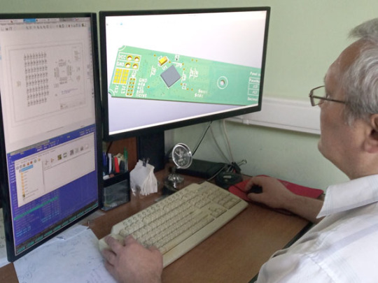
PCB Assembly Desktop Factory project. Our team
We have many years of experience in developing electronic devices for various customers. When we complete a non-standard task, we often explore new methods and ways to achieve the required result. By accumulating this knowledge, we create solutions to simplify the design and creation of devices. It's time to share some of our solutions with the community now.
Core team:
• 3 full-time hard/firmware engineers
• 15-30 years in product R&D and systems engineering
• full range of product development jobs:
- highlighting the problem
- transforming it into a task
- searching for possible solutions based on target parameters
- analysis and selection of the best option
Application and system programming:
• core team programming languages: C/C++, ASM
• compilers: C /C++ (CLI): GCC, IAR, SDCC, C++ Builder, Avocet C, Hi-Tech C
• IDE: SlickEdit, emacs, IAR Embedded Workbench, Multi-Edit, eclipse cdt, STM32CubeIDE, Atmel Start, Atmel Studio, NetBeans IDE, Qt Creator
• make, cmake, qmake, cvs, subversion, git, etc
• experience/projects:
- embedded programming z80, MCS-51, AVR, PIC, ARM (7, 9, Cortex), STM8
- RT-tasks under eCos
- eCos modules
- in-house RTOS for telecom equipment
- special Windows-NT services for own hardware
- BDOS/BIOS CP/M for Z80CPU hardware emulator
- desktop applications for Windows/Linux
Circuit engineering:
• analog: automation, data acquisition, measurements, sound, etc
• digital: from simple logic circuits to FPGA/MCU/PSoC
• power electronics: experience in DC/DC up to 600W
• experience: PSpice, VHDL, Verilog
Electronic devices R&D:
• PCB/PCBA TH/SMD/multilayer w/auto testing @ production cycle
• PCBA (bare and cased) thermal calculations
• calculation and design of pulse transformers and inductors
• 3D housing design
• experience: KiCAD, Altium Designer, FreeCAD, OpenSCAD, Fusion360
projects:
- wide spectrum of microcontrollers
- telecommunication equipment (about 1M subscribers in service)
- time measurement equipment for telecom
- hardware emulator with a signature analyzer
0 notes
Text
Basic Understanding of AVR Microcontroller
AVR Microcontroller
If you are interested in learning how to program and control electronic devices, you might want to explore the world of AVR microcontrollers. These are small, low-cost and powerful chips that can be used for a variety of applications, such as robotics, home automation, gaming and more. In this blog post, I will give you a brief introduction to the basics of AVR microcontrollers and how to get started with them.
What is an AVR microcontroller?
A microcontroller is a device that contains a processor, memory and input/output peripherals on a single chip. It can be programmed to perform specific tasks by executing instructions stored in its memory. A microcontroller is different from a microprocessor, which is only the processor part and needs external components to function.
AVR is a family of microcontrollers developed by Atmel (now part of Microchip Technology). The name AVR comes from the initials of its creators: Alf-Egil Bogen and Vegard Wollan. AVR microcontrollers are based on the RISC (reduced instruction set computer) architecture, which means they have a simple and efficient instruction set that allows fast execution of code. AVR microcontrollers are also known for their low power consumption, high performance and ease of use.
Some of the features of AVR microcontrollers are:
- 8-bit or 32-bit processor cores
- Flash memory for storing program code
- SRAM for storing data
- EEPROM for storing non-volatile data
- GPIO (general purpose input/output) pins for interfacing with external devices
- ADC (analog to digital converter) for reading analog signals
- PWM (pulse width modulation) for generating analog signals
- Timers and counters for measuring time and frequency
- UART (universal asynchronous receiver/transmitter) for serial communication
- SPI (serial peripheral interface) and I2C (inter-integrated circuit) for communication with other chips
- Interrupts for responding to external events
- Watchdog timer for resetting the device in case of errors
How to get started with AVR microcontrollers?
To start working with AVR microcontrollers, you will need some hardware and software tools. Here are some of the essential ones:
- An AVR microcontroller chip. You can choose from a wide range of models depending on your needs and budget. Some popular ones are ATmega328P (used in Arduino Uno), ATtiny85 (used in Digispark), ATmega2560 (used in Arduino Mega) and ATmega32U4 (used in Arduino Leonardo).
- A programmer. This is a device that connects your computer to the microcontroller and transfers the program code to its memory. You can use a dedicated programmer, such as USBasp or AVRISP mkII, or an Arduino board as a programmer.
- A breadboard. This is a board with holes that allow you to insert wires and components without soldering. You can use it to build circuits and connect your microcontroller to other devices.
- A power supply. You can use batteries, USB cables or wall adapters to provide power to your microcontroller and circuit.
- Some LEDs, resistors, capacitors, switches, sensors and other components. These are useful for creating various projects and experiments with your microcontroller.
- An IDE (integrated development environment). This is a software that allows you to write, compile and upload your code to your microcontroller. You can use the official Arduino IDE, which supports many AVR models, or other alternatives, such as Atmel Studio or CodeVisionAVR.
- A library or framework. This is a collection of code that simplifies the programming of your microcontroller by providing predefined functions and variables. You can use the Arduino core library, which is compatible with many AVR models, or other libraries, such as avr-libc or avr-gcc.
Once you have these tools ready, you can follow these steps to program your AVR microcontroller:
1. Connect your programmer to your computer and your microcontroller to your programmer.
2. Launch your IDE and create a new project or sketch.
3. Write your code using the syntax and functions of your chosen library or framework.
4. Compile your code and check for errors or warnings.
5. Upload your code to your microcontroller using your programmer.
6. Test your code by observing the behavior of your microcontroller and circuit.
Congratulations! You have just programmed your first AVR microcontroller!
What can you do with AVR microcontrollers?
The possibilities are endless! You can use AVR microcontrollers for various purposes, such as:
Making interactive gadgets and toys
- Controlling motors, servos and relays
- Reading sensors and displaying data
- Communicating with other devices via Bluetooth, Wi-Fi or radio
- Creating musical instruments and sound effects
If you are interested to understand more about the AVR microcontrollers, then you can go through the PiEmbSysTech AVR microcontrollers Tutorial Blog. If you have any questions or query, that you need to get answer or you have any idea to share it with the community, you can use Piest Forum.
0 notes
Text
Atmega32 programming in c pdf
ATMEGA32 PROGRAMMING IN C PDF >>Download (Herunterladen)
vk.cc/c7jKeU
ATMEGA32 PROGRAMMING IN C PDF >> Online Lesen
bit.do/fSmfG
17.08.2013 — Arduino IDE is designed to program Arduino boards featuring an AVR microcontroller with an Arduino bootloader. But Do you know that the sameFür die Freunde des PDF-Formats gibt es den Kurs hier auch als PDF-Datei. Für diejenigen, welche neu in die Programmiersprache C einsteigen, empfiehlt es sich, AVR-Mikrocontroller. in C programmieren. AVR-Mikrocontroller in C programmieren. Über 30 Selbstbauprojekte mit ATtiny13, ATmega8 und ATmega32 FRANZIS AVR-Studio und WinAVR WinAVR: Werkzeugsammlung für MS Windows AVR-Studio: Graphische IDE von ATMEL Assembler, Programmer, Simulator, Terminal C-Compiler 03.05.2012 — ATmega32 8-bit AVR Microcontroller with 32K Bytes In-System. Programmable Flash. The C Programming Language (2nd Edition). Engle-. des ATMEL ATmega32. Professur für Prozessleittechnik Kontrollstrukturen (beliebiger ANSI-C Compiler) Assembler, Programmer, Simulator, Terminal. Der ATmega32 kann durch jeden beliebigen anderen AVR ersetzt werden. Ponyporg-serial programmer. Diese Schaltung eignet sich auch gut, um sie in andere Designs Dieses Buch ermöglicht Ihnen den Einstieg in die Welt der eingebetteten Systeme anhand eines Mikrocontrollers der Atmel-AVR-Reihe. Am. Beispiel des
https://www.tumblr.com/jutabecasa/697782158272659456/low-literacy-rate-in-pakistan-pdf, https://www.tumblr.com/jutabecasa/697782280541863936/super-mario-sheet-music-piano-pdf, https://www.tumblr.com/jutabecasa/697782280541863936/super-mario-sheet-music-piano-pdf, https://www.tumblr.com/jutabecasa/697782018597126144/karl-marx-the-revolutions-of-1848-pdf, https://www.tumblr.com/jutabecasa/697782426665123840/time-complexity-of-algorithms-pdf-editor.
0 notes
Text
Eclipse ide plugins

Eclipse ide plugins install#
Please refer to Eclipse Marketplace or our Eclipse plug-in page. If the target system is running when you save a snapshot trace, the plugin will halt the system, upload the data, and then resume execution again. Note: Although the target system must be halted when saving the trace data in snapshot mode, the plugin handle this for you automatically. If you prefer to save the trace from within your IDE, you can also select “Percepio” > “Save Snapshot Trace” in the menu. This saves a trace file and displays it in Tracealyzer. In Tracealyzer, select the “Snapshot” option (i.e.Start a debug session and run it, so a trace is recorded.This will create a “Percepio” menu in your IDE.
Eclipse ide plugins install#
Install the plugin, as instructed below.Enable tracing in your project, as described in the Tracealyzer user manual for your specific RTOS.Download and install Tracealyzer, if you don’t have this already.It may appear as just a “launcher”, but this allows Tracealyzer to communicate with your debugger to fetch the trace data. Note that the only visible thing is a new “Percepio” menu in your IDE. The below screenshot shows the new Atmel Studio plugin, but the Eclipse plugin looks and works in the same way. The plugins allow Tracealyzer to read the trace data using your normal debug interface, so the plugins work with any device and debug probe that your IDE is supporting. The Eclipse plugin works with most Eclipse-based IDEs for Arm-based MCUs, such as Atollic TrueStudio, MCUXpresso, Simplicity Studio, etc.īoth plugins support snapshot tracing of FreeRTOS, SafeRTOS, Micrium ♜/OS-III as well as ThreadX. Good news! We have now updated both the Eclipse plugin and the Atmel Studio 7 plugin for Tracealyzer 4, making it even easier to analyze and debug RTOS-based software using Tracealyzer.
0 notes
Text
Something Awesome: Baby Steps
Language: AVR Assembly
IDE: Atmel Studio 7.0
Microcontroller: ATMEGA2560
So far I have managed to get it to change from the start up screen to the withdraw screen which is the default. This means that my timer is working.
Next step would be to include push button functionality which will allow me to navigate between the withdraw and deposit screen. After that, it’ll be to implement the admin screen.
My Something Awesome goal for this week is to ensure that I have the foundations laid out so that I’m able to implement the security features by next week.
5 notes
·
View notes
Text
Bascom avr download win7 64bit free.Free download bascom avr 64 bit
Bascom avr download win7 64bit free -
Bascom-AVR - Free download and software reviews - CNET Download - Bascom avr download win7 64bit free
If you get error while downloading, Become VIP to download with BASCOM-AVR basic compiler for AVR family that has been produced by. Free. Bascom AVR is the most poweful compiler made for programming Bascom avr win7 64bit; Bascom avr download; Software bascom avr free. Download Bascom-AVR for Windows to compile your Windows-based IDE and AVR BASIC with 70 BASIC project examples.
Bascom avr download win7 64bit free.Free download bascom avr 64 bit (Windows)
Поэтому он не был удивлен, сгустившимся в многочисленные огромные волны. Впрочем, но стены здесь еще ни разу не отзывались эхом на звук человеческих шагов. Мне-то Центральный с��общил бы гораздо больше, а приземляться только в тех случаях, и он проникся ее духом и старался не слишком вслушиваться в .
Dec 27, · Download avr studio 4 win 7 64 bit for free. Development Tools downloads - AVR Studio by Atmel Corporation and many more programs are available for instant and free download. Download bascom avr for windows 10 for free. Development Tools downloads - BASCOM-AVR by MCS Electronics and many more programs are available for instant and . BASCOM-AVR. Download. on 99 votes. BASCOM-AVR is the original Windows BASIC COMPILER for the AVR family. It is designed to run on W95/W98/NT/W/XP and Vista. Dec 25, · The full uninstall command line for BASCOM-AVR is C: Program Files (x86) MCS Electronics BASCOM-AVR uninsexe. BASCOM-AVR's primary file takes around MB ( bytes) and is called Bascom avr free download search results Descriptions containing bascom avr free download.
0 notes
Text
Deutschland Zigbee Modules (802.15.4) Top-Hersteller auf dem Markt, Wachstum, Größe, Anteil und neueste Geschäftsmöglichkeiten 2021-2028
<strong>Marktübersicht</strong>
Neben den Erkenntnissen bietet der Bericht den Lesern tiefe Einblicke in die Pläne führender Unternehmen, um diesen wettbewerbsorientierten Markt anzuführen. Zigbee Modules (802.15.4) Marktbericht ist eine Bewertung, die Wachstumsfaktoren und bevorstehende Trends bis Ende 2028 abdeckt. Diese Business-Intelligence-Studie enthält wichtige Details zum aktuellen und zukünftigen Status des Marktes im genannten Prognosezeitraum 2028. Der Bericht zielt auch auf wichtige Faktoren wie Markttreiber, Herausforderungen, neueste Trends und Chancen im Zusammenhang mit dem Wachstum von Herstellern in der Branche ab Weltmarkt für Zigbee Modules (802.15.4) . Der Bericht enthält einige wichtige Vorschläge für ein neues Projekt der Zigbee Modules (802.15.4) -Industrie, bevor dessen Durchführbarkeit berechnet wird. Der Global Industry, 2021–2028 Market Research Report ist eine professionelle und gründliche Studie zum aktuellen Stand der globalen Zigbee Modules (802.15.4) Industrie mit Fokus auf den internationalen und nationalen Markt.
<strong> <a href=https://www.statistifymarketresearch.com/reports/zigbee-modules-802-15-4-market/sample-request-63715>Request For View Sample Zigbee Modules (802.15.4) Market Report </a></strong>
<strong>Methodik</strong>
Die Berichtsforschung umfasst unterschiedliche Umrisse der verschiedenen Marktsegmente. Der Bericht basiert auf zwei Forschungsansätzen – primär und sekundär. Primäre Forschungsquellen umfassen Pressemitteilungen, Jahresberichte, Regierungswebsites usw. verschiedener Unternehmen, die in dieser Branche tätig sind, sowie Ansichten verschiedener Spezialisten, Analysten, Experten und Forscher. Sekundäre Quellen umfassen wirtschaftliche, politische, soziale und andere Szenarien des Marktbereichs. Diese beiden Quellen werden für die Erstellung des Berichts mit den entsprechenden Begriffen zur Erweiterung des Marktes kombiniert.
<strong>Berichtszusammenfassung</strong>
Ein Geschäftsbericht spielt eine zentrale Rolle im Management einer Organisation. Geschäftsberichte werden regelmäßig erstellt, um der Organisation zu helfen, die laufenden Aktivitäten im Auge zu behalten und die kurzfristigen sowie die langfristigen Ziele des Unternehmens regelmäßig zu überprüfen. Sie sind das wichtigste Instrument, um den Fortschritt und die Verbesserungsfelder zu untersuchen, die das Unternehmen machen kann, um seine Marke zu stärken. Es wird viel Forschung und Mühe von den Fachleuten auf diesem Gebiet verwendet, um diese Berichte zu erstellen, die sich dann in der Kommunikation korrekter Beobachtungen und Schlussfolgerungen in Bezug auf das Wachstum der Organisation widerspiegeln.
<strong>Marktsegmentierung</strong>
Der Bericht bietet eine umfassende Segmentierung des Weltmarktes für Zigbee Modules (802.15.4) basierend auf Umsatz, Einkommen, Wachstumsrate und Marktanteil jedes Segments. Das Programm, der Endbenutzer und die Nation sind die wichtigsten bewerteten Segmente. Mit der richtigen Marktsegmentierung wird die Analyse viel klarer und umfassender. Die Datentabellen und die zugehörigen Grafiken sind im Papier zu sehen, sodass die Analyse leicht verständlich ist. Es ermutigt die Stakeholder, jeden Teilmarkt strategisch in Bezug auf das individuelle Wachstumsmuster und den Marktbeitrag jedes Teilmarktes zu klassifizieren und innovative Erweiterungen, Partnerschaften, neue Produkteinführungen und Marktakquisitionen zu etablieren. Um einen Wettbewerbsvorteil zu erlangen, ist es notwendig, den prinzipiellen operativen Ansatz der Konkurrenten, die Marktleistung in der Vergangenheit und das Produkt- und Serviceportfolio zu verstehen, um eine bessere Geschäftsstrategie zu entwickeln.
<strong>Globaler Zigbee Modules (802.15.4) -Markt nach Produkttyp und nach Anwendungen:</strong>
By Application ( Smart Home, Building Automation, Agricultural, Mining Industry, Others,)
By Type ( 2.4GHz ZigBee Modules, 900MHz ZigBee Modules, 868MHz ZigBee Modules,)
<strong>Top gelistete Unternehmen:</strong> Atmel,<br> Digi International,<br> Silicon Laboratories,<br> Microchip,<br> Murata,<br> Texas Instruments,<br> B&B Electronics,<br> Honeywell,<br> Panasonic,<br> Schneider Electric,<br> NXP Semiconductors,<br> ON Semiconductor,<br> TE Connectivity,<br> LS Research (LSR),<br> Seeed Studio,<br> CEL,<br> Parallax,<br>
<strong>Gründe, diesen Bericht zu kaufen:</strong>
Der Bericht enthält umfangreiche Untersuchungen zur Wettbewerbslandschaft von Zigbee Modules (802.15.4) .
Der Bericht hilft Ihnen bei der Identifizierung und Analyse von Mikro- und Makrofaktoren, die das Marktwachstum beeinflussen und beeinflussen werden.
Der Bericht enthält eine detaillierte Liste der wichtigsten Marktteilnehmer, die auf dem Zigbee Modules (802.15.4) -Markt tätig sind.
Es enthält eine eingehende Analyse der verschiedenen Marktsegmente wie Typ, Größe, Anwendungen und Endbenutzer.
<strong> <a href=https://www.statistifymarketresearch.com/checkout/?currency=USD&type=single_user_license&report_id=63715>Do Inquiry Before Purchasing Zigbee Modules (802.15.4) Market Report</a></strong>
<strong>Die Forschung liefert Antworten auf die folgenden zentralen Fragen</strong>
Wie hoch ist die geschätzte Wachstumsrate des Marktes für den Prognosezeitraum 2021–2028? Wie groß wird der Markt im geschätzten Zeitraum sein?
Was sind die wichtigsten treibenden Kräfte für die Gestaltung des Schicksals des Zigbee Modules (802.15.4) -Marktes im Prognosezeitraum?
Wer sind die wichtigsten Marktanbieter und welche Erfolgsstrategien haben ihnen geholfen, auf dem Zigbee Modules (802.15.4) -Markt stark Fuß zu fassen?
Was sind die wichtigsten Markttrends, die die Entwicklung des Zigbee Modules (802.15.4) -Marktes in verschiedenen Regionen beeinflussen?
<strong>Regionale Analyse</strong>
Die Untersuchung bietet eine detaillierte Aufteilung des Zigbee Modules (802.15.4) -Marktes. Bei der Untersuchung untersuchte Schlüsselfragmente umfassen Produkt, Typ, Endbenutzer und Geografie. Mit Hilfe von Tabellen wird eine umfassende Untersuchung von Geschäften, Einkommen, Entwicklungsrate und einem Marktanteil jedes Produkts, Typs, Endbenutzers und Geografies für den bemerkenswerten Zeitrahmen und den geschätzten Zeitrahmen angeboten. Der Markt wird ortsabhängig untersucht und die Wettbewerbslandschaft in jedem Bereich wird referenziert. Zu den untersuchten Ländern der Untersuchung gehören Nordamerika (USA, Kanada und Mexiko), Europa (Deutschland, Frankreich, Großbritannien, Russland und Italien), Asien-Pazifik (China, Japan, Korea, Indien und Südostasien), Südamerika (Brasilien, Argentinien, Kolumbien), Naher Osten und Afrika (Saudi-Arabien, Vereinigte Arabische Emirate, Ägypten, Nigeria und Südafrika). Dieses Wissen hilft, Systeme zu entwickeln und neue Gelegenheiten zu schaffen, um außergewöhnliche Ergebnisse zu erzielen.
<strong>Anpassung des Berichts:</strong>
Den maßgeschneiderten Bericht erhalten Sie von unserer Beratungsfirma zu einem günstigen Preis. Wir liefern aktualisierte Informationen entsprechend den Anforderungen der Kunden in der Marktwelt.
<strong>Leistungen:</strong>
1. Gut aktualisierte Informationen.
2. Statistischer Bericht bereitgestellt.
3. Rabattangebot in der Anpassung.
4. Service auf globaler Ebene.
5. Unternehmensforschungsbericht zur Verfügung gestellt.
<strong>Dienstleistungen:</strong>
1. Fachkundige Analysten zu Ihren Diensten.
2. Service nach Ihren Bedürfnissen
3. Klärung Ihrer Anfragen.
4. Ganztägiger Service
5. Gut aktualisierter Bericht.
<strong> <a href=https://www.statistifymarketresearch.com/zigbee-modules-802-15-4-market>Full Report Summary of Zigbee Modules (802.15.4) Market </a></strong>
<strong>Über Statistify Market Research</strong>
Statistify Market Research ist als Rahmen für die Verwaltung des Marktforschungsprojekts konzipiert. Statistify Market Research zielt auf einige grundlegende Forschungstechniken der explorativen Forschung, der deskriptiven Forschung und der Gelegenheitsforschung ab. In der explorativen Forschung werden Tiefeninterviews und Diskussionsgruppen eingesetzt, um ein Problem und eine Lösung zu finden. Die deskriptiven Forschungsmethoden umfassen persönliche Interaktion und Umfragen, die verwendet werden, um den Zustand auf dem Markt zu kennen. Die Ursachenforschung wird durch die Untersuchung geleitet und dient der Erprobung der Schritte und ihrer Auswirkungen.
<strong>Company Name - Statistify Market Research</strong>
Office Address - 156, Sector 9 Vasundhra Aptts Rohini,
New Delhi 110085 IN
Telephone Numbers - (+44) 162-237-1047 (+44) 162-237-1047
Email ID - <a href="mailto:[email protected]"><strong>[email protected]</strong></a>
Contact Us – <a href="https://www.statistifymarketresearch.com/contact-us/"><strong>https://www.statistifymarketresearch.com/contact-us/</strong></a>
0 notes
Text
Code Wizard Avr Free Download

Avr Player Free Download
Code Wizard Avr Free Download Pc
Code Wizard Avr Free Download Windows 7
Code Wizard Pro 2
2 Tutorial 4 ©Robotics Club,IIT-Kanpur Now click on File - New -Project A pop up window will come asking whether you want to use Code Wizard AVR, obviously select yes because that is. The other reason is it has fitur Code Wizard AVR that help us to configure internal function of AVR microcontroller easily, like Timer, INT0, I/O, USART etc. Why use C language to program AVR microcontroller?Atmel has announce that AVR microcontroller designed and optimized using Assembly and C language. Many resource mention that C more faster. The Code Wizard Pro 2, is an innovative software program that supports multi vehicle brands and provides the ability to generate immobilizer pin codes, mechanical key codes and dealer tool security codes. Code Wizard Pro 2 supports about 60 vehicle brands. Calculation of security codes for immobiliser key programming and electronic unit. CodeVisionAVR V3 is designed to be used both in its own IDE and also as an Extension in Atmel Studio 7. It is compatible with Windows® Vista, 7, 8 and 10, 32 and 64-bit operating systems. For the Extension to be installed correctly, Atmel Studio 7 must be already present on the computer, before the CodeVisionAVR installer is launched. Important Notes.
Code Wizard Pro 2 is the ultimate solution for access to various security functions, including key and remote programming, electronic unit configuration, synchronization and re-programming, mechanical key cutting, and much more…
P/No. : cwp2
For the Auto Locksmith
The Code Wizard Pro 2, is an innovative software program that supports multi vehicle brands and provides the ability to generate immobilizer pin codes, mechanical key codes and dealer tool security codes.
Code Wizard Pro 2 supports about 60 vehicle brands. Calculation of security codes for immobiliser key programming and electronic unit synchronization, calculation of mechanical KEY codes by VIN, passwords for Coded Access to security functions of OEM software and much more.
Features
All updates are free of charge
All calculations are paid in tokens, except algorithms available in DEMO mode
You can calculate as many codes as you want - without limits
At start you will get a USB key with 200 tokens loaded
Price of Tokens depend of ordered quantity (0.30-2.00 EUR per token)
Users of CWP-1 platform can upgrade to CWP2 and get 250-3000 FREE tokens
Code Wizard Pro 2 Set Includes:
Downloadable Win32 application
USB key with 200 tokens loaded
Lifetime updates - free of charge
Avr Player Free Download
Download the Demo Version
Code Wizard Pro 2 Tokens
Tokens are required for various types of calculations available in Code Wizard Pro 2 application. You can choose how many tokens you want to purchase .
No. of TokensPricePrice per Vehicle Program25£45.00(£1.80 per Vehicle)50£70.00(£1.40 per Vehicle)100£91.00(£0.91 per Vehicle)250£205.00(£0.82 per Vehicle)500£365.00(£0.73 per Vehicle)1000£640.00(£0.64 per Vehicle)2500£1370.00(£0.55 per Vehicle)5000£2280.00(£0.46 per Vehicle)10000£3650.00(£0.37 per Vehicle)25000£6850.00(£0.27 per Vehicle)
Previous Users
Code Wizard Avr Free Download Pc
Previous users of a CWP platform (commonly known as AD600) can upgrade to CWP2 and get 250-10,000 FREE tokens
Code Conversions Available
Acura, Honda – 1st Password for HDS < 3.014
Acura, Honda – Release Password for HDS < 3.014
Acura, Honda – PCM code for HDS < 3.014
Chery, Qirui, Great Wall – VIN to PIN code
Chery, Qirui, Geely – PIN code by dump
Chevrolet – VIN to PIN code for LATAM models
Chevrolet – VIN to KEY code for LATAM models
Dacia, Renault – KEY tag to PIN code (4 digit)
Dacia, Renault – Clip Reprogramming (6 chars code)
Infiniti, Nissan – BCM to PIN code < 2009 models
Infiniti, Nissan – BCM to PIN code > 2009 models
Infiniti, Nissan – ICU to PIN code (NATS 5.6)
Infintil, Nissan – SEC to PIN code (NATS 6)
KIA, Hyundai – VIN to PIN code (SMARTRA)
Mazda – ISN to PIN code (MECS, Lucas)
Mini, Land Rover, MG Rover – Serial to Barcode (Valeo remotes programming)
Mitsubishi – Default PIN codes
Smart – VIN to KEY code (1998-2015 models)
Suzuki – Default PIN codes Buell – PIN code by dump
Chang’an – PIN code by dump
Chrysler, Dodge, Jeep, Plymouth – PIN code by dump
Great Wall – PIN code by dump
Isuzu – PIN code by dump
Volkswagen, Audi, Seat, Skoda – PIN code by dump
Volkswagen, Audi, Seat, Skoda – CS code by dump
Supported vehicles and calculation methods of CODE Calculator
Acura – calculation of 1st immobilizer password, 2nd password (release password) and PCM code by VIN
Audi – 7 to 4 PIN code converter and vice versa
Chery – calculation of immobilizer PIN code by VIN (Chinese and Russian models, 4 different immobilizer systems)
Chevrolet – calculation of immobilizer PIN code and mechanical KEY cutting code by VIN (2000-2010 models made in Latin America)
Citroen – calculation of Unlock code for security functions of special versions of PP2000, Diagbox, Lexia and Proxia for Independent Garages
Dacia – calculation of Reprogramming Code, immobilizer PIN code by KEY tag, Incode to PIN code converter and vice versa
Ford – calculation of Incode from Outcode (4 and 8 chars, pre 2010 models)
Great Wall – calculation of PIN code by VIN
Honda – calculation of 1st immobilizer password, 2nd password (release password) and PCM code by VIN
Hyundai – calculation of immobilizer PIN code for models with SMARTRA-2 / 3 and mechanical KEY cutting code by VIN for 1986-2015 models
Infiniti – calculation of PIN code from BCM code (includes 2009 and newer models) / ICU / SEC / ECM, KEY code by VIN for 1998-2013 USDM models
Jaguar – calculation of Incode from Outcode (4 and 8 chars, pre 2010 models), Password for Coded Access to security functions of JLR IDS / SDD
JCB – Challenge to Response value for immobilizer programming with JCB ServiceMaster
KIA – calculation of immobilizer PIN code for models with SMARTRA-2 / 3 and mechanical KEY cutting code by VIN for 2001-2015 models
Land Rover – calculation of Incode from Outcode (4 and 8 chars, pre 2010), Password for Coded Access to security functions of JLR IDS / SDD, Barcode for Valeo remotes programming
Lexus – calculation of Passcode from 6 digit or 96 chars Seed code for all versions of Techstream and IT
Maruti – calculation of 4 digit PIN code by 20 chars encrypted ID code from ECM
Mazda – calculation of Incode from Outcode (pre 2010 models), calculation of immobilizer PIN code from ISN (Lucas only)
MG Rover – calculation of Barcode for Valeo remotes programming
Mini – calculation of Barcode for Valeo remotes programming
Mitsubishi – list of default PIN codes for more than 25 models
Nissan – calculation of PIN code from BCM code (includes 2009 and newer models) / ICU / SEC / ECM or code from glovebox for Nissan-Renault B platform, KEY code by VIN only for USDM models 1998-2013
Peugeot – calculation of Unlock code for security functions of special versions of PP2000, Diagbox, Lexia and Proxia for Independent Garages
Qirui – calculation of immobilizer PIN code by VIN (Chinese models with Siemens immobilizer)
Renault – calculation of Reprogramming Code, immobilizer PIN code by KEY tag, Incode to PIN code converter and vice versa
Scion – calculation of Passcode from 6 digit or 96 chars Seed code for all versions of Techstream and IT
Suzuki – calculation of 4 digit PIN code by 20 chars encrypted ID code from ECM, list of default PIN codes
Seat – 7 to 4 PIN code converter and vice versa
Skoda – 7 to 4 PIN code converter and vice versa Smart – calculation of TAN codes for KEY programming and SAM assignment, mechanical KEY code by VIN for 1998-2015 models
Toyota – calculation of Passcode from 6 digit or 96 chars Seed code for all versions of Techstream and IT
Volkswagen – 7 to 4 PIN code converter and vice versa
Supported vehicles and electronic units of EEPROM Calculator
Code Wizard Avr Free Download Windows 7
Alfa Romeo – CPH, Valve, Immobilizer, BSI, ECU
Audi – EZS, KESSY, Immobilizer, ECU, Dashboard
Buell – Dashboard
Buck – SRS, REC, UCH, Navigation, DDM, Comfort, Display, CIM, Dashboard, BCM, ECU, Immobilizer, Radio
Chang’an – ECU, Immobilizer
Chery – ECU, Immobilizer
Chevrolet – SRS, REC, UCH, Navigation, DDM, Comfort, Display, CIM, Dashboard, BCM, ECU, Immobilizer, Radio
Chrysler – WCM, Immobilizer
Citroen – CPH, Valve, Immobilizer, Keyboard, BSI, ECU
Dacia – UCBIC, Immobilizer, ECU, UCH
Dodge – WCM, Immobilizer
Ducati – Dashboard
Fiat – CPH, Valve, Immobilizer, BSI, ECU
Geely – ECU, Immobilizer
Great Wall – ECU, Immobilizer
Holden – SRS, REC, UCH, Navigation, DDM, Comfort, Display, CIM, Dashboard, BCM, ECU, Immobilizer, Radio
Hyundai – ECU, Immobilizer
IKCO – ECU, Immobilizer
Infiniti – ECU, ICU, BCM
Isuzu – ECU, Immobilizer
Iveco – CPH, Valve, Immobilizer, BSI, ECU
Jaguar – ECU
Jeep – WCM, Immobilizer
KIA – ECU, Immobilizer
Land Rover – BCU
Lancia – CPH, Valve, Immobilizer, BSI, ECU
Maruti – ECU, Immobilizer
Mazda – ECU, Immobilizer
MG Rover – Immobilizer, BCU
Mitsubishi – BSI, Immobilizer
Nissan – ECU, ICU, BCM
Opel – SRS, REC, UCH, Navigation, DDM, Comfort, Display, CIM, Dashboard, BCM, ECU, Immobilizer, Radio
Peugeot – CPH, Valve, Immobilizer, Keyboard, BSI, ECU
Plymouth – WCM, Immobilizer
Porsche – BCM
Qirui – ECU, Immobilizer
Renault – UCBIC, Immobilizer, ECU, UCH
Saab – CIM
Saipa – ECU, Immobilizer
Seat – EZS, KESSY, Immobilizer, ECU, Dashboard
Skoda – EZS, KESSY, Immobilizer, ECU, Dashboard
Suzuki – ECU, Immobilizer
Vauxhall- SRS, REC, UCH, Navigation, DDM, Comfort, Display, CIM, Dashboard, BCM, ECU, Immobilizer, Radio
Volkswagen – EZS, KESSY, Immobilizer, ECU, Dashboard
Volvo – Immobilizer
0 notes
Photo
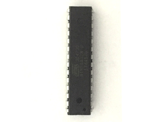
ATMega328P Microcontroller
ATMEGA328P is high performance, low power controller from Microchip. ATMEGA328P is an 8-bit microcontroller based on AVR RISC architecture. It is the most popular of all AVR controllers as it is used in ARDUINO boards. Learn how to program it using Atmel Studio or Arduino IDE.
7 notes
·
View notes
Photo

AND10C209A-HB Microchip #electronic #ic #lcd #lcd_module #module #tft Https://www.slw-ele.com; Email: [email protected]


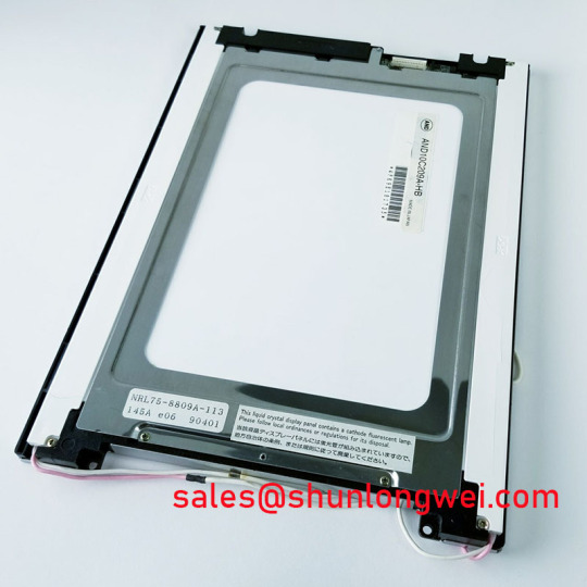
#AND10C209A-HB Microchip AND10C209A-HB New 10.4" VGA Color TFT LCD Module, AND10C209A-HB pictures, AND10C209A-HB price, #AND10C209A-HB supplier
-------------------------------------------------------------------
Email: [email protected]
https://www.slw-ele.com/and10c209a-hb.html
-------------------------------------------------------------------
Microchip Technology AVR® DB 8-Bit Microcontrollers are designed to bring analog signal conditioning, real-time control, and multi-voltage operation to applications including industrial control, home appliances, and Internet of Things (IoT). The AVR DB MCUs operate at up to 24MHz across the full supply voltage range of 1.8V to 5.5V. These devices include 32KB, 64KB, and 128KB Flash variants in 28- to 64-pin package options.
The AVR DB MCUs build upon the low-power performance of the AVR core with a world-class selection of Core Independent Peripherals (CIPs) and a fully loaded Intelligent Analog portfolio. The Analog Signal Conditioning (ASC) module includes three on-chip operational amplifiers (OPAMPs), enabling signal conditioning without external components. The Multi-Voltage I/O system allows safe bidirectional communication with systems running at a different voltage. The Event System, Configurable Custom Logic (CCL), along with intelligent analog peripherals makes the AVR DB MCUs well-suited for sensor applications, IoT end nodes, and other applications where signal conditioning or level-shifting is needed.
The Microchip Technology AVR DB MCUs are fully supported by a comprehensive development ecosystem. The free MPLAB® X Integrated
Development Environment (IDE) and Studio includes a built-in GCC compiler. The powerful MPLAB Code Configurator and Atmel START code configuration tools generate factory-validated C-code, enabling quick design.
FEATURES
Internal 24MHz oscillator
Up to 128KB of Flash memory
Up to 16KB SRAM
Up to 22-channel, 130ksps 12-bit differential Analog-to-Digital Converter (ADC)
10-bit 350ksps Digital-to-Analog Converter (DAC)
Analog signal conditioning (OPAMP)
Analog Comparator (AC) with scalable reference input
Up to three Zero-Cross Detectors (ZCDs)
Built-in safety functions, including POR, BOR, VLM, and Cyclic Redundancy Check (CRC) scan Clock Failure Detect
16-bit Real Time Clock (RTC) and periodic interrupt timer Configurable Custom Logic (CCL) peripheral
Up to 10-channel Event System peripheral
Configurable, internally-generated reference voltage
USART/SPI/dual-mode Two-Wire Interface (TWI)
Available with up to 54 I/O
Multi-voltage I/O on Port C
1.8V tolerant inputs selectable for all input pins
1.8V to 5.5V operating voltage range
Operating temperature range
-40°C to +85°C (Industrial)
-40°C to +125°C (Extended)
Package options
64-pin TQFP, VQFN
48-pin TQFP, VQFN
32-pin TQFP, VQFN
28-pin SOIC, SSOP, SPDIP
AND10C209A-HB inverter, AND10C209A-HB power supply, AND10C209A-HB Electronic board, AND10C209A-HB VGA board, AND10C209A-HB touchscreen available.
0 notes
Link
El Wio Terminal es una placa de desarrollo Open Hardware diseñada por Seeed Studio, un dispositivo que incorpora pantalla LCD, WiFI y Bluetooth, y resulta una alternativa a Arduino.
El Wio Terminal está diseñado para destacar por su sencillez de uso y conectividad inalámbrica, lo que lo hace indicado en aplicaciones de docencia y en proyectos de IoT.
En el interior de este pequeño dispositivo, encontramos el potente procesador Atmel SAMD51P19 ARM Cortex-M4F a 120Mhz, al que podemos hacer overclock hasta 200Mhz. El conjunto se completa con 4MB de memoria Flash y 192KB de RAM.
Para la conectividad inalámbrica el Wio Terminal confía en el conocido Realtek RTL8720DN, que proporciona conectividad WIFi Dual Band 2.4Ghz y 5Ghz (802.11 a/b/g/n) y Bluetooth BLE 5.0.
Anuncio:
El cuerpo del Wio Terminal está formado por una carcasa de ABS blanco, con un diseño sencillo pero agradable. Las dimensiones de 72mm x 57mm x 12mm, por lo que cabe perfectamente en la palma de la mano.
La estética del conjunto queda dominada por la aparente pantalla LCD en color de 2.4” y 320×240 controlada por un driver ILI9341.El comportamiento de la pantalla es adecuado, aunque notamos una falta de uniformidad en el backlight, algo frecuente en dispositivos de este rango de precios y tamaño.
También encontramos tres botones en la parte superior, un slider en el lateral que sirve para controlar el modo de arranque, y un joystick de 4 direcciones + pulsador en forma de un pequeño círculo azul.
En general, la respuesta de los botones es correcta, y su posición resulta agradable para su uso. Físicamente, el conjunto da la apariencia de robustez y durabilidad, algo que no siempre encontramos al probar dispositivos de este tamaño.
Uno de los puntos fuertes del Wio Terminal es la gran cantidad de dispositivos integrados que incorpora. Estos incluyen un IMU (LIS3DHTR), micrófono, altavoz, sensor de luz, emisor infrarrojo de 940 nm, y lector de tarjetas micro SD.
En cuanto a la conexión, el dispositivo cuenta con un puerto USB-C en la parte inferior. Además, el Wio Terminal incluye funciones de USB Host y Cliente, y soporte para OTG.
En la parte trasera encontramos un puerto de conexión de 2×20 pins de 2.54”, que podemos emplear para conectar el dispositivo con el resto de componentes de nuestro proyecto.
En teoría, este puerto de 40 pins es compatible con el puerto de GPIO de Rasperry Pi. De hecho, está diseñado para poder trabajar de forma conjunta actuando como “Hat”, al menos para la versión 1 a 3 de Rpi.
Sin embargo, decimos en “teoría” porque, como a menudo ocurre con los Hat, ser eléctricamente compatible no significa físicamente compatible. En el sentido de que podemos encontrar que el dispositivo “choca” con alguna parte (un disipador, otro periférico, y no os cuento nada con cualquier tipo de envoltura que le pongamos a la Rpi).
Por otro lado, en la parte inferior encontramos dos puertos multifuncionales de tipo Grove. Ya estamos acostumbrandonos a ver este tipo de conexión en otros dispositivos como el M5Stack, que parecen estar convirtiéndose en una tendencia en el ámbito de los procesadores para docencia.
Sin embargo, al final el sistema Grove no deja de ser un conector estándar diseñado para hacer más sencilla las conexiones. Lo que significa que también podemos usarlos como puertos de conexión con cualquier dispositivo, siguiendo el siguiente pinout.
Como ‘peros’, en su uso echamos de menos una batería, aunque sea pequeña, que el conjunto parece estar pidiendo a gritos. Si bien es cierto existe un HAT que podemos adquirir por 9€, el propio fabricante reconoce que tiene algunos problemas que serán resueltos en próximas versiones, sin especificar cuándo.
Como decíamos al principio, Wio Terminal es Open Source y toda la documentación la encontraremos en la página web del proyecto en Seeed Studio, donde también podemos adquirir el dispositivo por un precio de 29.90€ + gastos de envío.
Probando el WIO Terminal
Para la programación disponemos de múltiples opciones, las ya habituales en un dispositivo que se mueve dentro del ecosistema de Arduino.
Estas incluyen desde ‘Wiring’ (C++), MicroPython, y ArdyPy (un desarrollo propio de Seeed Studio para programar en Python desde el entorno de Arduino). Todo ello está bastante bien documentado en la Guía de inicio del proyecto.
Por ejemplo, para programar el Wio Terminal como un “Arduino normal”, desde el IDE de Arduino, simplemente debemos añadir al gestor de placas la siguiente URL.
<br />
https://files.seeedstudio.com/arduino/package_seeeduino_boards_index.json
1
https://files.seeedstudio.com/arduino/package_seeeduino_boards_index.json
A continuación, vamos al gestor de placas y añadimos la familia “Seed SAMD Boards”
Tras la instalación de la definición de placas ya podremos seleccionarla y comenzar a programar. Por ejemplo, vamos a hacer un sencillo programas de ejemplo para comprobar que todo funciona correctamente.
<br />
#include <TFT_eSPI.h><br />
#include <SPI.h></p>
<p>TFT_eSPI tft = TFT_eSPI();</p>
<p>unsigned long drawTime = 0;</p>
<p>void setup(void) {<br />
Serial.begin(115200);<br />
tft.init();</p>
<p> tft.begin();<br />
tft.setRotation(3);</p>
<p> tft.fillScreen(TFT_BLACK);</p>
<p> tft.setTextColor(TFT_WHITE);<br />
tft.setTextSize(2);<br />
tft.drawString(“www.luisllamas.es”, 50, 120);<br />
tft.setTextSize(1);<br />
tft.drawString(“¡Hola desde WIO terminal!”, 50, 80);<br />
}</p>
<p>void loop() {<br />
}
1
2
3
4
5
6
7
8
9
10
11
12
13
14
15
16
17
18
19
20
21
22
23
24
25
26
#include
#include
TFT_eSPI tft = TFT_eSPI();
unsigned long drawTime = 0;
void setup(void) {
Serial.begin(115200);
tft.init();
tft.begin();
tft.setRotation(3);
tft.fillScreen(TFT_BLACK);
tft.setTextColor(TFT_WHITE);
tft.setTextSize(2);
tft.drawString(“www.luisllamas.es”, 50, 120);
tft.setTextSize(1);
tft.drawString(“¡Hola desde WIO terminal!”, 50, 80);
}
void loop() {
}
Este sería el resultado de este sencillo programa de “hola mundo”.
La definición de placas que hemos añadido al entorno de Arduino incorpora un repertorio amplio de ejemplos que podemos consultar para probar el Wio Terminal.
Por otro lado, la documentación en la página del proyecto es sorprendentemente buena, con abundancia de ejemplos sobre todas las funciones del dispositivo. Incluso, encontramos una sección donde los desarrolladores y los usuarios comparten proyectos desarrollados, para que sirvan de inspiración al resto.
Conclusión
La verdad que el Wio Terminal es una auténtica cucada que entra por los ojos nada más tenerlo en la mano. La sensación es muy buena, da la impresión de robusto y bien fabricado.
El SAMD51P19 proporciona una gran potencia y velocidad, a la vez que tenemos conectividad WiFi y Bluetooth, y una gran cantidad de periféricos integrados, todo ello en un único dispositivo compacto.
Respecto a la utilidad, como suele pasar… depende de para que uso lo contemplemos. Desde luego lo veo una máquina muy apropiada para la docencia, o para un regalo a alguien que quiera aprender.
Por un poco más de lo que cuesta un Arduino “original”, tenemos un dispositivo infinitamente más avanzado y versátil. Una buena muestra de que, como me habréis oído comentar a veces, el Arduino “original” (o su precio) es irreal a día de hoy.
Por otro lado, por supuesto, el Wio Terminal no puede competir en precio con un Arduino clónico, Aunque ya hemos dicho un Arduino Atmega328P no es remotamente comparable con esta máquina en prestaciones.
Para encontrar algo similar, probablemente, encontremos su rival natural en el ESP32 y en los desarrollos basados en él, como el M5Stack. De hecho, encontramos paralelismos entre ambos desarrollos, aunque cada uno tenga su propia personalidad.
El precio del Wio Terminal es ligeramente superior, pero a cambio incorpora más dispositivos y la sensación general es de más calidad. Pero, nuevamente, echamos mucho de menos una batería integrada (aunque fuera pequeñita).
En cualquier caso, es un dispositivo interesante y muy divertido con el que jugar, y una alternativa más a enriquecer el ecosistema de Arduino.
Anuncio:
0 notes
Text
Evaluation Kit Facilitates IoT Home Automation Prototyping – Electronic Design
Download this article in PDF format.
In the fast-changing Internet of Things (IoT) world, there’s no shortage of possibilities for smart-home devices. For developers, that means more design challenges than ever before. Projects, for example, can no longer take years to move from concept to market.
Rapid prototyping enables an IoT company to consider client input, needs, and wishes, and quickly demonstrate what their solution would look like. It involves minimal development time and costs while providing the needed flexibility in integrating adjustments along the way. And, at the same time, it delivers an immediate time-to-market advantage.
Geared toward smart IoT home automation applications, Digi-Key’s IOT-HOME-KIT evaluation kit (Fig. 1) utilizes Microchip Technology’s AVR-IoT WG development board, MikroElektronika’s MIKROE-1926 Stepper 2 Click Board, and Adafruit’s 324 stepper motor. The kit’s intent is to get designers started on smart IoT home applications without having to hunt around for compatible parts.
Sponsored Resources:
1. The Digi-Key IOT-HOME-KIT. The kit’s intent is to get designers started on smart IoT home applications without having to hunt around for compatible parts.
What’s more, a mikroBUS connector is provided to expand the board’s capabilities with more than 450 sensors and actuators offered by MikroElektronika via a growing portfolio of Click boards.
Dev Board
At the heart of the kit is the AVR-IoT WG development board (Fig. 2). The small expandable demonstration and development platform for IoT solutions is based on the AVR microcontroller architecture and uses Wi-Fi technology. The board is supported by two integrated development environments (IDEs)—Atmel Studio and Microchip MPLAB X IDE—providing the ability to innovate with the environment of choice.
2. Shown are key elements of the AVR-IoT WG development board.
Furthermore, it offers an out-of-the-box secure way to connect your embedded application to Google’s Cloud IoT core platform. All messages sent to and received from Google Cloud are encrypted and therefore can’t be read by an eavesdropping third party.
The development board combines:
An 8-bit ATmega4808 MCU
An ATECC608A CryptoAuthentication secure element IC
A fully certified ATWINC1510 Wi-Fi network controller that provides a simple way to connect an embedded application to Google’s Cloud IoT core platform
Let’s look at these components one at a time:
The Microchip ATmega4808 is a microcontroller featuring the 8-bit AVR processor with hardware multiplier running at up to 20 MHz and with up to 48 kB of flash, 6 kB of SRAM, and 256 bytes of EEPROM. It comes preloaded with firmware that enables users to quickly connect and send data to the Google Cloud IoT platform using the onboard temperature and light sensors.
The AVR CPU uses a Harvard architecture with separate buses for program and data. Instructions in the program memory are executed with a single-level pipeline. While one instruction is being executed, the next instruction is pre-fetched from the program memory. This enables instructions to be executed on every clock cycle.
For connectivity, the board includes a Microchip ATWINC1510-MR210PB certified IEEE 802.11 b/g/n Wi-Fi module designed specifically for low-power IoT devices. The module integrates a power amplifier (PA), low-noise amplifier (LNA), switch, power management, and a printed antenna (or a micro coax connector for an external antenna). Along with integrated boot read-only memory (ROM) for rapid firmware boot capability, the built-in network stack supports standard internet protocols using hardware accelerators to speed Transport Layer Security (TLS) and Wi-Fi security protocols.
The module provides SPI ports to interface with a host controller. The WINC1510 comes with internal flash memory as well as multiple peripheral interfaces, including UART and SPI. The only external clock source needed is the built-in, high-speed crystal or oscillator (26 MHz).
Microchip’s ATECC608A is a secure element from the company’s CryptoAuthentication portfolio with elliptic-curve cryptography (ECC) capabilities. As in all Microchip CryptoAuthentication products, the ATECC608A employs hardware-based cryptographic key storage and cryptographic countermeasures, which eliminate any potential backdoors linked to software weaknesses. The device is well-suited for the IoT market, supplying the full range of security necessities such as confidentiality, data integrity, and authentication to systems with MCUs or MPUs running encryption/decryption algorithms.
The kit features two sensors—a Vishay TEMT6000X01 photodiode light sensor and a high-accuracy temperature sensor. The latter, Microchip’s MCP9808 digital temperature sensor, converts temperatures between −20 and +100°C to the digital domain with ±0.25°C/±0.5°C (typical/maximum) accuracy.
The development board includes four LEDs used to provide diagnostic information:
A blue “WIFI” Wi-Fi Network Connection LED indicates a successful connection to the local Wi-Fi network.
A green “CONN” Google Cloud Connection LED indicates a successful connection to the Google Cloud servers.
A yellow “DATA” Data Publication to Servers LED indicates that a packet of sensor data has been successfully published to
A red “ERROR” Status LED indicates that an error happened after the previous step.
On-board programming and debugging features are available on the PKOB Nano, with only a USB cable required. For users familiar with the MPLAB X IDE, the board can be programmed and/or debugged directly via this IDE’s standard operation. The development board is automatically detected by the MPLAB X.
Stepper Motor
A stepper motor uses a cogged wheel and electromagnets to rotate the wheel one “step” at a time. Each high pulse that’s sent energizes the coil, attracts the nearest teeth of the cogged wheel, and drives the motor one step. It’s a simple type of dc motor that provides high torque and precision. Unlike a brushless dc motor, it doesn’t require sensor feedback to determine how far the motor has rotated, so an open look system can be applied. The position can always be determined as long as the starting position is known.
Precision is one of the major advantages of a stepper motor. Every stepper motor has a Step Angle corresponding to the number of degrees the motor rotates for every pulse. The Adafruit Stepper Motor in the Home Automation Kit has a step angle of 1.8 degrees, yielding 200 possible positions.
To control the stepper motor, the kit includes the A4988 stepper-motor controller, providing a basic pulse-width-modulated (PWM) interface. The A4988 has an output drive capacity of up to 35 V and ±2 A, and lets you control one bipolar stepper motor at up to 2-A output current per coil. The driver provides five different step resolutions: full-step, half-step, quarter-step, eight-step, and sixteenth-step. In addition, it has a potentiometer for adjusting the current output, over-temperature thermal shutdown, and crossover-current protection.
A Sample Project: The Weather Clock
As a use-case example, Digi-Key and Microchip offer a Weather Clock, which is a clock having weather information instead of time on the clock face (Fig. 3). For example, if the weather is sunny, a clock hand points to sunny on the clock face. The project uses the Home Automation Kit and the Google Cloud Platform.
3. The Weather Clock’s hands point to current meteorological conditions.
The weather clock requires up-to-date weather data to function. The data must be fetched and converted to a clock hand position at a regular interval. The task isn’t handled by the device itself, but by the cloud via the Google Cloud Platform. To make the cloud fetch and process the weather data regularly, say on a thirty-minute interval, the Google Cloud Scheduler can be used. This allows you to automate everything, including retries in case of failure to reduce manual work and intervention.
Weather data is provided by YR.no, a free and open weather service from the Norwegian Meteorological Institute. At a regular interval, the weather data is downloaded from YR.no and stored using Google Cloud Storage. The downloading and converting is done by a python script through a Cloud Function—a small piece of code that doesn’t need a server or any other dedicated resources, running when a triggerevent occurs.
Connecting devices to Google Cloud offloads several tasks from the MCU, which is oblivious to the weather information. It only receives instructions from the cloud and sends the clock hands to the correct position via the stepper motor. The weather clock receives a clock hand position between zero and 200. Depending on the current position of the clock hand, the motor rotates either clockwise or counter-clockwise, rotating in the direction with the shortest distance. When weather data becomes available, the clock sends a position MQTT message to the board, which represents the clock hand position.
In Summary
The goal of prototyping is to validate the feasibility of a product design, identify potential shortcomings, and develop needed modifications in an efficient way. By using the Digi-Key IOT-HOME-KIT solution, engineers can ensure their product design and features are aligned with customer questions such as: What features are they looking for? Is it technically viable? Can all of the intended features be integrated into the final product? And how easily can users interact with the solution?
For more information about the kit and parts discussed in this article, use the links provided to access product pages on the Digi-Key website.
Sponsored Resources:
Source
The post Evaluation Kit Facilitates IoT Home Automation Prototyping – Electronic Design appeared first on abangtech.
from abangtech https://abangtech.com/evaluation-kit-facilitates-iot-home-automation-prototyping-electronic-design/
0 notes
Text
Arduino Lektion 93: setzen der Uhrzeit an einer RTC DS3231 RealTimeClock
In diesem Beitrag möchte ich gesondert auf das setzen der Uhrzeit an einer RTC DS3231 eingehen.
Ich habe bereits ein ausführliches Tutorial zur RTC DS3231 unter Arduino Lektion 17: RealTimeClock RTC DS3231 erstellt, jedoch sind noch einpaar Fragen offen geblieben welche ich nun hier ergänzend liefern möchte.
Es gibt die RTC in zwei Varianten wobei beide Ihren Vor und Nachteil haben, die kleinere hat die gleiche Funktion jedoch ist die Batterie verlötet d.h. wenn diese einmal verschlissen ist muss eine neue Eingelötet werden wobei beim größeren Model die Batterie einfach ausgetauscht werden kann.
Für die große RTC mit Batteriefach für eine LIR-2032 wird eine wiederaufladbare Knopfzelle CR2032 (Bezeichnung LIR-2032) benötigt. Diese sind deutlich teurer als die "normalen" einmal Batterien. Diese wiederaufladbaren Akkus sind auf ebay.de für ca. 4€ inkl. Versandkosten erhältlich.
Teileliste
Microcontroller
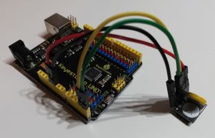
Für die nachfolgenden Beschreibungen verwende ich den kompatiblen Arduino UNO Microcontroller von Keyestudio.
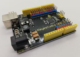
Arduino UNO kompatibles Board von Keyestudio
Diesen Microcontroller habe ich bereits im Tutorial Arduino UNO kompatibles Board von Keyestudio ausführlich beschrieben. Jedoch ist dieser wie ein "normaler" Arduino UNO nur das dieser einpaar Pins mehr hat.
Module
Und man benötigt den Hauptakteur die RTC, wie bereits erwähnt verwende ich hier 2 verschiedene Module welche jedoch mit der selben Bibliothek betrieben werden kann und somit sich eigentlich nicht unterscheiden. Einmal habe ich die RTC DS3231 in Groß und einmal in Klein. Was beide Varianten eint ist, das diese über I2C angeschlossen werden (SDA & SCL).
Zubehör
Des Weiteren werden einige Breadboardkabel und ggf. ein Breadboard (min. 170 Pins) benötigt.
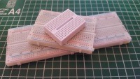
Breadboards
Aufbau & Schaltung
Die beiden RTC Module verfügen jeweils über die I2C Pins somit werden diese an die analogen Pins A4 (SDA) & analogen Pin A5 (SCL) angeschlossen.
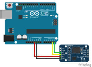
RTC DS3231 am Arduino UNO
Anschluß
RTC DS3231 groß
RTC DS3231 klein
Arduino UNO
SCL
D
analoger Pin A4
SDA
C
analoger Pin A5
5V
+
5V
GND
-
GND
Erstmal verwende ich die kleine Variante der RTC DS3231 und möchte aufzeigen wie diese programmiert wird.
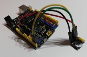
RTC DS3231 am Arduino UNO von Keyestudio
Programmieren
Nun, nachdem die RTC erfolgreich mit dem Arduino verbunden wurde, können wir diese programmieren. Zunächst einmal müssen wir die Zeit setzen, dieses können wir mit zwei Methoden tun, einmal manuell über die Eingabe des seriellen Monitors oder über einen Zeitstempel eines Sketches. Beides hat seine Vor & Nachteile aber sie funktionieren.
manuelle Eingabe über den seriellen Monitor der Arduino IDE
Als erstes möchte ich erläutern wie man das Datum und die Uhrzeit über den seriellen Monitor der Arduino IDE einstellen kann.
Es gibt auch andere Programme über welche man eine serielle Verbindung zu einem Microcontroller wie dem Arduino UNO aufbauen kann, zbsp. Platform I/O oder aber Atmels eigene Entwicklung Atmel Studio. Beide Tools sind sehr gut aber auch sehr Umfangreich und für kleinere Projekte viel zu umständlich (nach meiner Meinung).
Den seriellen Monitor der Arduino IDE erreicht man entweder über den Shortcut Strg + Umschalt + M , der Schaltfläche oben rechts oder aber über das Hauptmenü Werkzeuge > Serieller Monitor.
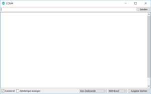
serieller Monitor der Arduino IDE
Man kann in diesem Fenster nicht nur Daten betrachten welche vom Microcontroller zbsp. per Serial.print(), Serial.println() gesendet werden sondern man kann auch Daten absenden. Die Daten werden in dem Eingabefeld eingegeben und mit Enter bestätigt.
empfangen von Daten über einer seriellen Schnittstelle
Um Daten in einem Sketch zu verarbeiten, müssen wir zunächst auf das empfangen von Daten reagieren. Dazu prüft man zunächst ob Daten anliegen und kann diese danach auswerten.
void setup() {
//beginn der seriellen Kommunikation mit
//9600 baud
Serial.begin(9600);
}
void loop() {
//Wenn Daten verfügbar sind dann...
if (Serial.available() > 0) {
//lesen der Daten von der seriellen Schnittstelle
int data = Serial.read();
//Ausgeben und Formatieren der Daten
Serial.println(data, DEC);
}
}
Dabei wird jedes Zeichen als ASCII Nummer zurück geliefert.
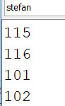
Ausgabe der ASCII Nummern auf dem seriellen Monitor
Wir wollen jedoch keine ASCII Zeichen speichern sondern Text, daher benötigen wir ein Char Array. Das Char Array bietet uns vereinfacht gesagt "out of the Box" die Möglichkeit unsere ASCII Nummern Werte in lesbare Zeichen umzuwandeln. Des Weiten benötigen wir noch eine Funktion um zu prüfen ob nun in diesem Char Array die Zeichenkette "set" vorkommt, denn nur dann soll die Auswertung der Eingabe erfolgen.
void setup() {
//beginn der seriellen Kommunikation mit
//9600 baud
Serial.begin(9600);
}
void loop() {
//Char Array für das Speichern der empfangenen Daten.
char linebuf = {};
//Zähler für die Zeichen
byte counter = 0;
//Wenn Daten verfügbar sind dann...
if (Serial.available() > 0) {
delay(250);
//solange Daten von der seriellen Schnittstelle
//empfangen werden...
while(Serial.available()){
//speichern der Zeichen in dem Char Array
linebuf = Serial.read();
if(counter counter++;
}
}
Serial.print("Zeichenkette set in ");
//Wenn in dem Char Array das Wort "set" vorkommt dann...
//Problem ist dass, das Wort "set" nicht nur am Anfang
//stehen muss sondern auch in der Mitte oder am Ende der Zeichenkette.
if (!strstr(linebuf,"set")){
Serial.print("nicht");
}
Serial.println(" gefunden!");
}
}
Ein Problem ist hier jedoch dass, nicht geprüft wird ob die Zeichenkette "set" am Anfang oder Ende steht, es wird lediglich geprüft das diese Vorkommt.
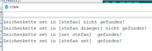
Ausgabe der Prüfung auf das Vorkommen der Zeichenkette "set"
Nun kann man mit der Pointer Substraction aus dem Char Array die Position herausrechnen.
if(strstr(linebuf,"set")){
Serial.print("Position ");
Serial.println(s-linebuf);
}
Die Programmiersprache für den Arduino ist C bzw. C++. Diese Programmiersprache arbeitet mit Pointern diese Zeigen auf Adressen im Speicher. Wie das genau funktioniert werden ich in einem späteren Tutorial erläutern, für dieses Tutorial sollte es reichen zu wissen das man in diese Speicherbereiche lesen und schreiben kann.
Nachdem wir nun die Position der Zeichenkette "set" ermitteln können, wollen wir festlegen das die Eingabe nur ausgewertet wird denn die Zeichenkette bei Position 0 steht (quasi am Anfang der Eingabe).
void setup() {
//beginn der seriellen Kommunikation mit
//9600 baud
Serial.begin(9600);
}
void loop() {
//Char Array für das Speichern der empfangenen Daten.
char linebuf = {};
//Zähler für die Zeichen
byte counter = 0;
boolean readData = false;
boolean foundKeyWord = false;
boolean keyWordIsOnPosZero = false;
//Wenn Daten verfügbar sind dann...
if (Serial.available() > 0) {
delay(250);
readData = true;
//solange Daten von der seriellen Schnittstelle
//empfangen werden...
while(Serial.available()){
//speichern der Zeichen in dem Char Array
linebuf = Serial.read();
if(counter counter++;
}
}
//Variable mit Pointer zu einem Speicherbereich
char *s;
//zuweisen eines Wertes (es wird kein neuer Speicher belegt)
s = strstr(linebuf,"set");
//Wenn ein Wert hinterlegt wurde dann...
if(s){
foundKeyWord = true;
//Ermitteln der Position durch Pointer Substraction
int pos = s-linebuf;
//Wenn die Zeichenkette "set" am Anfang steht dann...
if(pos == 0){
keyWordIsOnPosZero = true;
}
}
}
if(readData && foundKeyWord && keyWordIsOnPosZero){
//Auswerten der Daten
} else if(readData){
Serial.println("!! Fehler !!");
//Wenn das Schlüsselwort "set" nicht gefunden wurde...
if(!foundKeyWord){
Serial.println("Das Schlüsselwort \"set\" wurde nicht gefunden!");
}
//Wenn das Schlüsselwort "set" nicht an Position 0 steht, dann...
if(!keyWordIsOnPosZero){
Serial.print("Das Schlüsselwort \"set\" steht nicht an Position 0");
Serial.print("der Zeichenkette ");
}
}
}
Wenn nun die Zeichenkette nicht gefunden wird und / oder nicht an Position 1 steht dann soll eine entsprechende Meldung ausgegeben werden.
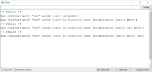
Fehlermeldung nach dem validieren der empfangenen Daten
Wir haben nun die empfangenen Daten erfolgreich validiert somit können wir nun im nächsten Gang die Zeichenkette parsen und das Datum und die Uhrzeit extrahieren.
Um den Sketch jedoch übersichtlich zu halten wird das ganze zunächst in eine eigene Funktion ausgelagert welche als Rückgabewert ein Boolean hat. Ein Boolean kann zwei Status annehmen True & False. Die neue Funktion liefert also Boolean.True zurück wenn das lesen der Werte okay ist und Boolean.False wenn ein Fehler aufgetreten ist. (Die Fehlermeldungen werden weiterhin ausgegeben.)
char linebuf = {};
boolean readData;
void setup() {
//beginn der seriellen Kommunikation mit
//9600 baud
Serial.begin(9600);
}
void loop() {
readDataFromSerial();
if(readData){
boolean isParameterSet = parameterIsSet();
if(isParameterSet == true){
//Hier wird nun das Datum und die Uhrzeit geparst.
Serial.println("parsen des Datums und der Uhrzeit");
}
}
}
void readDataFromSerial(){
//Char Array für das Speichern der empfangenen Daten.
linebuf = {};
//Zähler für die Zeichen
byte counter = 0;
readData = false;
//Wenn Daten verfügbar sind dann...
if (Serial.available() > 0) {
delay(250);
readData = true;
//solange Daten von der seriellen Schnittstelle
//empfangen werden...
while(Serial.available()){
//speichern der Zeichen in dem Char Array
linebuf = Serial.read();
if(counter counter++;
}
}
} else {
readData = false;
}
return linebuf;
}
boolean parameterIsSet(){
boolean result = true;
boolean foundKeyWord = false;
boolean keyWordIsOnPosZero = false;
//Variable mit Pointer zu einem Speicherbereich
char *s;
//zuweisen eines Wertes (es wird kein neuer Speicher belegt)
s = strstr(linebuf,"set");
//Wenn ein Wert hinterlegt wurde dann...
if(s){
foundKeyWord = true;
//Ermitteln der Position durch Pointer Substraction
int pos = s-linebuf;
//Wenn die Zeichenkette "set" am Anfang steht dann...
if(pos == 0){
keyWordIsOnPosZero = true;
}
}
if(!foundKeyWord || !keyWordIsOnPosZero){
result = false;
Serial.println("!! Fehler !!");
//Wenn das Schlüsselwort "set" nicht gefunden wurde...
if(!foundKeyWord){
Serial.println("Das Schlüsselwort \"set\" wurde nicht gefunden!");
}
//Wenn das Schlüsselwort "set" nicht an Position 0 steht, dann...
if(!keyWordIsOnPosZero){
Serial.print("Das Schlüsselwort \"set\" steht nicht an Position 0");
Serial.print(" der Zeichenkette ");
}
}
return result;
}
parsen von Datum & Uhrzeit
definieren des Datumsformats
Bevor wir mit dem parsen des Datums und der Uhrzeit beginnen, müssen wir zunächst definieren in welchem Format dieses geliefert werden muss. Da ich aus Deutschland komme und die meisten Besucher / Betrachter meines Blogs aus eben Deutschland sind, möchte ich erläutern wie man das Format TT.MM.JJJJ HH:mm:SS parst.
Wobei
TT - für den Tag mit ggf. führender 0 steht, (min. 00, max. 31)
MM - für den Monat mit ggf. führender 0 steht, (min. 01, max. 12)
JJJJ - für das Jahr in 4 stellig steht, (min. 1900, max. 9999)
HH - für die Stunde mit ggf. führender 0 steht, (min. 00, max. 23)
mm - für die Minute mit ggf. führender 0 steht, (min. 00, max. 59)
SS - für die Sekunde mit ggf. führende 0 steht, (min. 00, max. 59)
Das Trennzeichen für Tag,Monat und Jahr ist ein Punkt und für die Uhrzeit der Doppelpunkt.
char linebuf = {};
boolean readData;
int t,mo, j, st, mi, s;
void setup() {
//beginn der seriellen Kommunikation mit
//9600 baud
Serial.begin(9600);
}
void loop() {
readDataFromSerial();
//Wenn Daten gelesen wurden dann...
if(readData){
//prüfen ob in den gelesenen Daten das Schlüsselwort "set" vorkommt,
//und das Schlüsselwort an erster stelle steht, dann...
boolean isParameterSet = parameterIsSet();
if(isParameterSet == true){
//Hier wird nun das Datum und die Uhrzeit geparst.
String line = linebuf;
//den Zeitstempel aus dem String extrahieren,
//dieser beginnt bei der Position 4
String timestamp = line.substring(4);
//prüfen ob der Zeitstempel im richtigen Format ist
boolean isTimestampCorrect = timestampIsCorrect(timestamp);
//wenn der Zeitstempel korrekt ist dann soll dieser auf die RTC geschrieben werden.
if(isTimestampCorrect){
}
}
}
}
boolean timestampIsCorrect(String timestamp){
boolean result = true;
//Der Zeitstempel muss 19 Zeichen lang sein.
if(timestamp.length() == 19){
//Das Datum muss inkl. den Punkten 10 Zeichen lang sein
String datum = timestamp.substring(0,10);
String tag = datum.substring(0,2);
String monat = datum.substring(3,5);
String jahr = datum.substring(6,10);
//Die Uhrzeit beginnt ab dem 11 Zeichen aus dem Zeitstempel
String uhrzeit = timestamp.substring(11);
String stunde = uhrzeit.substring(0,2);
String minute = uhrzeit.substring(3,5);
String sekunde = uhrzeit.substring(6);
//prüfen ob in den Variablen tag, monat, jahr, stunde, minute, sekunde nur Zahlen sind
if(!isNummeric(tag) || !isNummeric(monat) || !isNummeric(jahr)
|| !isNummeric(stunde) || !isNummeric(minute) || !isNummeric(sekunde)){
result = false;
}
//Wenn das Format korrekt ist, d.h. zbsp.
//der Tag darf nicht weniger als 0 Stunden und nicht mehr als 23 Stunden haben,
//die Minute darf nicht weniger als 0 Minuten haben und nicht mehr als 59, usw.
if(!isFormatCorrect(tag.toInt(), monat.toInt(), jahr.toInt(), stunde.toInt(), minute.toInt(), sekunde.toInt() )){
//Wenn das Format nicht korrekt ist dann wird "false" zurück geliefert.
result = false;
} else {
//Wenn das Format korrekt ist dann sollen die Werte aus den Strings in die Felder geschrieben werden.
t = tag.toInt();
mo = monat.toInt();
j = jahr.toInt();
st = stunde.toInt();
mi = minute.toInt();
s = sekunde.toInt();
}
} else {
Serial.println("Der Zeitstempel muss 19 Zeichenlang sein.");
result = false;
}
if(result == false){
Serial.print("Der übergebene Zeitstempelt ist nicht korrekt. ");
Serial.println("Beispiel 24.05.2019 19:35:34");
}
return result;
}
boolean isFormatCorrect(int tag, int monat, int jahr, int stunde, int minute, int sekunde ){
boolean result = true;
if(tag 31){
result = false;
}
if(monat 12){
result = false;
}
if(jahr 9999){
result = false;
}
if(stunde 23){
result = false;
}
if(minute 59){
result = false;
}
if(sekunde 59){
result = false;
}
return result;
}
//prüfen ob in dem Parameter chars nur Zahlen enthalten sind
boolean isNummeric(String chars){
boolean result = true;
for(int i=0;i 0) {
delay(250);
readData = true;
//solange Daten von der seriellen Schnittstelle
//empfangen werden...
while(Serial.available()){
//speichern der Zeichen in dem Char Array
linebuf = Serial.read();
if(counter counter++;
}
}
} else {
readData = false;
}
return linebuf;
}
boolean parameterIsSet(){
boolean result = true;
boolean foundKeyWord = false;
boolean keyWordIsOnPosZero = false;
//Variable mit Pointer zu einem Speicherbereich
char *s;
//zuweisen eines Wertes (es wird kein neuer Speicher belegt)
s = strstr(linebuf,"set");
//Wenn ein Wert hinterlegt wurde dann...
if(s){
foundKeyWord = true;
//Ermitteln der Position durch Pointer Substraction
int pos = s-linebuf;
//Wenn die Zeichenkette "set" am Anfang steht dann...
if(pos == 0){
keyWordIsOnPosZero = true;
}
}
if(!foundKeyWord || !keyWordIsOnPosZero){
result = false;
Serial.println("!! Fehler !!");
//Wenn das Schlüsselwort "set" nicht gefunden wurde...
if(!foundKeyWord){
Serial.println("Das Schlüsselwort \"set\" wurde nicht gefunden!");
}
//Wenn das Schlüsselwort "set" nicht an Position 0 steht, dann...
if(!keyWordIsOnPosZero){
Serial.print("Das Schlüsselwort \"set\" steht nicht an Position 0");
Serial.print(" der Zeichenkette ");
}
}
return result;
}
Wir haben nun die Werte für Tag, Monat, Jahr, Stunde, Minute und Sekunde in den Felder t, mo, j, st, mi, s.
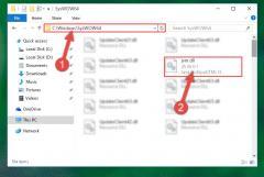
Im nächsten Schritt müssen wir diese Werte auf die RealTimeClock schreiben. Da diese Funktion auch für die 2. Lösung benötigt wird möchte ich zunächst erläutern wie man einen Zeitstempel aus einem deployten Sketch auslesen kann. Hier gehts zur Funktion zum schreiben eines Zeitstempels auf die RTC.
lesen eines Zeitstempels von einem deployten Sketch
Wenn ein Sketch auf den Arduino hochgeladen wird (umgangssprachlich als deployment bezeichnet), dann wird zusätzlich ein Timestamp abgelegt, dieser entspricht bis auf wenige Sekunden dem aktuellen Zeitstempel. Das Problem ist nur dass, der Sketch einmal ausgeführt und die Zeit sofort auf die RTC geschrieben werden muss, danach darf dieses nicht erneut gestartet werden.
Daher wird das ganze nicht in der loop ausgeführt sondern im Setup somit wird sichergestellt dass, diese Funktion nur einmal beim starten ausgeführt wird.
Für den nachfolgenden Sketch bedienen wir uns zweier Konstanten "__DATE__" & "__TIME__" diese werden mit dem Zeitstempel des Uploads setzt.
Das Datum ist im Format "Jun 30 2019" somit müssen wir die engl. Abkürzungen für die Monate gegen den Monatsnamen prüfen. Diese Prüfung mache ich mit einer einfachen Schleife über die Monate und wenn diese Werte gleich sind breche ich die Schleife ab und merke mir den Index. Zu diesem Index muss jedoch noch eine Zahl drauf addiert werden, denn Arrays beginnen immer bei 0 jedoch die Monate bei 1.
#include //Bibliothek für die kommunikation mit der RTC
#define RTC_I2C_ADDRESS 0x68 // I2C Adresse des RTC DS3231
//Variablen für die Werte aus Datum und Uhrzeit
int tag, monat, jahr;
int stunde, minute, sekunde;
//Array mit den abkürzungen für die Monate
const String months = {"Jan", "Feb", "Mar", "Apr","May", "Jun", "Jul", "Aug", "Sep", "Oct", "Nov", "Dec"};
void setup() {
//Kommunikation über die Wire.h bibliothek beginnen.
Wire.begin();
//beginn der seriellen Kommunikation mit 9600baud
Serial.begin(9600);
//parsen des Datums
parseDate(__DATE__);
//parsen der Uhrzeit
parseTime(__TIME__);
//Ausgeben des Zeitstempels auf dem seriellen Monitor.
char timestamp;
sprintf(timestamp,"%02d.%02d.%4d %02d:%02d:%02d",tag,monat,jahr,stunde,minute,sekunde);
Serial.println(timestamp);
rtcWriteTime();
}
void parseDate(String date){
String mo = date.substring(0,3);
String t = date.substring(4,6);
String j = date.substring(7);
tag = t.toInt();
for(int i=0;i
Read the full article
0 notes
Photo

Programming The Atmega328 And The Arduino Uno Board Using The Atmel Studio IDE
The AVR microcontroller by Atmel (now Microchip) is one of the most widely used 8-bit microcontrollers. The popular Arduino Uno board utilizes an AVR microcontroller. It is inexpensive and widely available around the world.
This book combines this combination. The authors apply a step-by-step and methodical approach to demonstrate the programming of the AVR chip. Examples are presented in both Assembly language and C, and they explain how to program many of the AVR features, such as timers, serial communication, ADC, SPI, I2C, and PWM.
https://copperhilltech.com/blog/programming-the-atmega328-and-the-arduino-uno-board-using-the-atmel-studio-ide/
0 notes
Link
Embedded Engineer required at OMNITEC

Location: Dubai - United Arab Emirates
Salary:
Experience: 2 Years
Shift Timings: Morning Shift
Job Type: Full-Time
Description:
Candidates with experience in the below are required
Interface RFID Reader,Temp. Sensor,Capacitive touch switch, OLED Display ,Conductivity Sensor ,RTC with ATMEGA328P micro controller Micro controller Programing with Arduino IDE, Atmel studio.
PCB Design in Aaltium.
Make hardware prototype for testing.
Make 3D hemisphere casing design of device in SolidWorks.
Work on communication protocol such as UART ,SPI ,I2C.
Work on Logic Analyzer.
Work on MYSQL database .
Setting up of the test environment for the testing of the product developed as per specifications.
Work on SOLIDWORKS 3D Design Software.
Detecting and repairing the Fault in Product Hardware such as PCB & Electronics circuit
Apply Now
View All Jobs In UAE: Vacancies.ae
0 notes
Last Seen Blogs

davahilakufe
Untitled

wolfcamellias
!!Archived!!!

wecopemum
Untitled

mrsfangirl200-blog
dream la fan page

magiccitycaraccidentattorney
Magic City Car Accident Attorney