#whats the point. why. i just have to desolder it to make it work. what is the purpose
Text
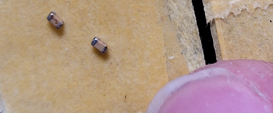
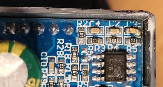
So a week or three ago, I was attempting to figure out why this variable DC-to-DC step-up/step-down converter module I’d obtained to use as a cheap bench power supply wasn’t displaying amps correctly - the screen kept showing around 300 mA even when the current limiting was set and correctly limiting the current to something as low as 20 mA. The problem appears to have been just poor connection between the two boards of the module, but in attempting to remove a large blob of obstructing glue, I accidentally managed to cut against one of the surface-mounted capacitors with my hobby knife, damaging it - see capacitor C3 here.

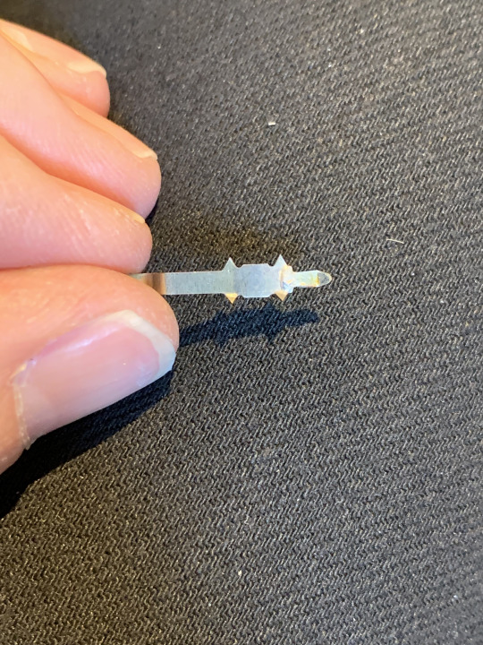
For a sense of scale, here’s that same capacitor shown on the tip of my finger after I desoldered it from the board.

Yeah.
Unfortunately, SMD capacitors tend not to have any markings on them to denote what kind of capacitance they have, unlike SMD resistors - see the black rectangles with text in white? The 01C code on the nearby ones mean they’re 10 kΩ resistors, while the 01A at R18 means 100 Ω. Anyway this basically meant I was left with a bit of guesswork as to what the damaged component was supposed to be, and testing it with my multimeter gave me varying results bouncing in between around 5 to 12 nF without ever settling at any one specific point.
Fortunately, from what I could find online suggested it was a capacitor sitting the end of a circuit with one end connected straight to ground (which it was) and should likely be in the 0.1 to 0.01 µF range, with only limited importance to the exact value.
Well, since there’s a thousand nano to every micro and 0.01 µF is therefore 10 nF which was rather close to the 5-12 nF range I’d measured, so I went about desoldering a bunch of still working SMD capacitors from circuit boards pulled out of non-working electronic devices I had laying around, and then the fiddly work of trying to measure them to find one with the right capacitance.
After a few hours of work, managing to damage another 7 or so capacitors but successfully remove maybe about 20 unharmed ones, I found two capacitors of the right size that both read around 10 nF each.
Putting one of them into place to replace the damaged one was yet more fiddly work and it ended up a bit skew, but it seems to work - I haven’t done extensive testing since I’m still in the process of putting together all the parts which’ll go into the box that the DC-to-DC module will sit in to make for a complete variable lab bench power supply, but it did turn on and seemed to work, so hopefully all is well.
And if not, I guess I’ll find out if the module burns out or fries an LED or an IC or something on me. Most simple electronic components aren’t very expensive, fortunately.
And that was my latest adventure in the Holy Shit These Godsdamned Components Are Tiny of electronics.
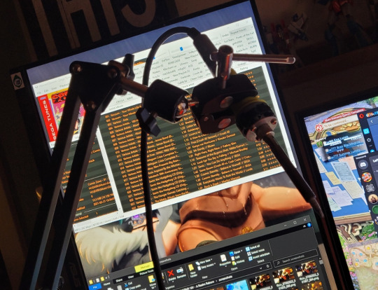
shout-out to the desk lamp arm that I rigged up to hold my soldering iron for me because I can’t get my hands to keep it steady - godsdamned hand tremors and fine motor control issues.
1 note
·
View note
Text
Soundcraft Shithead
Right so I played at Showa Techno April 29th. Some really neat acts this year (as every year). Personal favorites this time were Jin-Cromanyon (of course), T.S.P. (nice improv, 2P battle style techno), and Hidetaka Matsumae (fantastic). Lemme see if I can put a link up to my set from the show here...
undefined
youtube
Yeah so there ya go. Make sure to read the video description for all the gory details. Some stupid shenanigans went on that I wrote about there so do check it out. The video is just a slideshow of gear photos, and maybe a smidge of video from the event, but not a video of my performance (didn’t feel like bothering with shooting video this time). It was fun. I’ll do it again next year.
So, Soundcraft. Yeah. A while back I bought a used Spirit Folio Si 18-2, and used that for the show. I was running the Mix Inserts to a Focusrite Compounder, but the signal started getting scratchy and intermittent, and I had to fuck with the jacks to get it to stay stable. Aaaaargh. Two weeks ago, the left insert just totally shat itself, no signal unless I pushed super hard sideways on the cable and I knew that was definitely Not A Good Thing. So fine then time for some surgery.

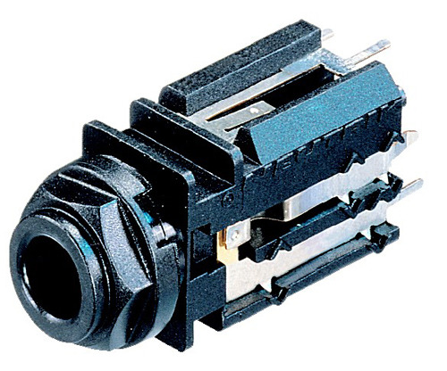
Here’s the mixer. The Mix Inserts are in the back row of sockets at the upper right, middle row, second and third over from the right. The jacks Soundcraft went with on this mixer are a funky kind made by Neutrik. All plastic body, with a plastic retainer ‘nut’ that can be removed by inserting a coin into the + and gently rotating to the left. It’ll make a nice CLICK and then you can carefully pull the ‘nut’ off. I’m not so sure how I feel about these. For ease of disassembly, compared to metal threaded jacks with actual nuts and washers, these Neutriks are definitely the winner. But they’re plastic, and plastic is obviously not as robust as metal, so you have to wonder about the lifespan of the ‘nut’ part itself. In any case, opening the mixer wasn’t a huge pain in the ass.

Underside of the PCB. It’s all one gifuckingnormous PCB, which was a nice surprise. (Mackie I’m looking at you here). Pretty easy to navigate, and as these are Made In England the soldering and build was actually very, very good (sorry if I offend anyone but fuck made in china, end of brief rant, we now return to program in progress). I desoldered the L Mix Insert jack to see what there was to see. This is what I seed:
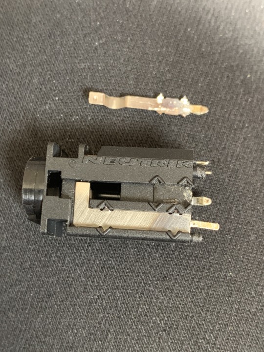
Well, the little metal part there had worked its way loose. It seems the ‘teeth’ that are used to hold these things in had worn away at the plastic after who knows how many times a cable was inserted and removed over how many years. Ok. At this point I had two questions. First, is this part still available, as the mixer is from the early 2000s? Second, is flattening the teeth out and snapping the metal piece back in going to work (or last)? The answer to the first question was yes. After some data sheet detective work, I found out that the currently available part (NJ5 FD-V) has the same footprint and is basically drop-in compatible. The only difference is that the ‘nut’ is no longer a + shaped weirdo, but looks like a nut. Here:
Anyway, I ordered two pairs from Mouser, but for the time being, finagled and Ghetto Engineered the metal piece back in, re-soldered it, and so far it’s been working fine. So the answer to the second question is a tentative yes. Here’s more fun photos:

In any case, I’m happy I got the thing working again. These mixers hit the spot in a way that no other fucking mixer on the market since has. Tons of stereo inputs, a minimal pair of mono inputs. I have shitloads of stereo stuff, be it synths themselves or synths being run through stereo effects units/pedals. I don’t need a half-dozen mono channels. WHY ARE THERE NO MIXERS LIKE THIS?!!?! 2 mono (with mic pre-amp), and 8 stereo channels. Nice EQs. Sweepable mid on the mono channels. Tape input. Monitor and Main outputs. Mix Inserts. The only thing I wish it had was a Mute button on every channel. Why they left that out bewilders me. Anyway, when the Insert shat itself I immediately jumped to the Worst Case Scenario Useless Mixer Dilemma Must Buy Replacement Immediately If Not Sooner Arrrgh, and bought another one off Digimart (an online amalgamate of new and used gear shops here in Japan). So, the latest incarnation of the Lab Of Machines Of Nefarious And Questionable Repute looks like this:

Under the pimped out MPC500 you can see a HHB Radius 3 Fat Man Stereo Tube Compressor (made by TL Audio). I tooled with a Presonus Bluetube DP for a bit but it wasn’t what I was after. This thing though, fucking hell. Or more like FUCKING HELL YES! I swapped the factory tube out with a Mullard tube and have the Spirit Folio Lite Mix Inserts running to it. I’m using that little mixer as a sub-mixer for all my drum machines. Let me just say, I am fucking more than happy with this. Warms up and glues the drum mix together SO NICELY. I’m toying with the idea of picking up NOS tubes periodically to see how the character of the sound changes. Need a budget first... (sigh).
That’s about it for this time, kiddies. I’ll end with some shameless self-promotion and throw up some action photos from the show. Take care y’all!


#fucktrump#showa techno 2019#soundcraft#soundcraft spirit folio si#soundcraft spirit folio lite#neutrik#neutrik jack repair#hhb radius 3 fat man#mullard#satan#darkness#闇
3 notes
·
View notes
Text
How To Choose Desoldering Station
Desoldering Station through-hole parts with two or three legs, is pretty uncomplicated. Apply heat and also some fresh solder to the underside and pull them out from the top. Yet when it comes to chips and components with more pins, this approach doesn't work.
Some people master using the small pen-shaped 'solder-suckers'. The suggestion is that you thaw the solder with an iron, and also as quickly as the solder is molten, position the solder-sucker over the joint and launch the springtime to suck up the solder. I have actually attempted and fallen short to learn that skill.
Enter Stage Left, The Desoldering Station.
Advance Tech makes use of a hollow tip soldering iron and also a vacuum pump, to ensure that solder removal is a LOT much easier than trying to use a pen-style solder-sucker.
I bought the design shown (Katsu ZD-8915 Desoldering Station) from Amazon, yet they are likewise offered on ebay.com and also I make sure somewhere else also.
What you obtain The bundle consisted of:
the control device, that reveals both the actual and also set temperature levels (approximately 480C). desoldering weapon.
two spare suggestions of different hole dimensions, offering you three suggestions in total (1.0, 1.2 and also 1.5 mm).a good solid means the desoldering gun. extra wadding pads. three sizes of cleaning tools to poke out the solder from the hollow nozzle. a factually proper yet not very useful instruction book.

Whatever meshed very well as well as actually seemed like it was respectable high quality. The solder chamber including the spring-loaded piston needs to be occasionally emptied of solder and in the beginning time is a bit complex, as the wadding and also steel disk simply rest versus the spring as well as fall out when you open the chamber. Putting it back in, it took me a while to know that the wadding pad enters initially, adhered to by the metal disk. After making use of the gun for a while I knew why there were parts of the wadding, as it gets sprayed with solder.
Below's what I discovered to benefit me, Desoldering Station some DIL 7-segment LED modules for method. Push the rear of the piston down to prime the spring.
Apply warm to the solder joint up until the solder melts (applying a little bit of fresh solder as well as adjusting the temperature as required). Pull the trigger to turn on the suction pump.
Change the angle of the nozzle to get as excellent a fit over the solder joint as feasible. I located that if you paid attention to the air pump you might hear it work harder when you get a much better seal.
Launch the piston to make the final suck and also you ought to see a splodge of solder fly up the see-through piston and embed itself in the cotton. That's the enjoyable little bit! Evaluate the joint and repeat if required.
Get a flat-bladed screwdriver under the thing you are Desoldering Station and carefully lever it out - desoldering some more if it won't move.
Really feeling very happy with my brand-new purchase, I turned it off as well as went and had some lunch. When I pertained to starting once again, it didn't appear to be drawing.
I had actually bunged up the nozzle, just where it fulfills the cylindrical tube. It after that took about an hour of poking, transforming the temperature, running in more solder as well as also gathering fluid change. At some point I unblocked it by taking the front off the weapon and also poking the solder out by rodding it from the opposite side. Obviously this was completely my fault and also I wish to state I have actually learned my lesson, but its rather feasible that I'll neglect it again.
0 notes
Text
About my “lab”
Welcome to my electronic lab! Over the last few years or so many people asked me about my personal lab, so today I am giving you a virtual tour of it.
We will go over what gear I use and how I set everything up so I can do my experiment efficiently. Along the way I will answer the questions that has been asked about my setup in my various posts. In particular, I will provide a rationale of why I choose one type of hardware versus another. The quantity of hardware described in this post might seems overwhelming but keep in mind here that it took me years to build this lab. I merely add a new piece here and there based of my needs and opportunity.
Disclaimer: I don’t claim my setup is the best but it works for my use-cases: tinkering with electronic, doing security research and repairing various pieces of equipment. If you have suggestions on how to improve it, let me know.
Overall setup
All my equipment is installed on a big and stable desk that I bought from IKEA (BEKANT model). As extra storage room, I used an extra thick shelf from IKEA as well (LACK model). Sadly the brackets (IKEA Ekby Töre model) used to fix the shelf to the desk without drilling are discontinued which prevents me from adding an additional shelf. If you know a place where I can find a similar product let me know.
All units are connected to an Intel NUC Swift Canyon barebone either via Ethernet or via USB when Ethernet is not supported. The NUC has 32GB of RAM and a 512GB SSD. This small PC allows me to handle the firmware upgrades, capturing screenshots of the different gears at once, handle the software defined radio (SDR) through its front USB3 port, dump NAND flash memories, etc. And the form factor is just great, leaving most of the space free. The 23” LCD screen is mounted on a Ergotron articulated arm. Again, the rationale here is just to keep the workspace clean.
To avoid damaging the wood of the desk, I put an ESD mat from Vermason. It provides a good protection and also has a standard ESD stud on each corner. I’m using that have a standard ESD wristband and the soldering station is also connected to it. I never felt that ESD protection was mandatory but considering that the mat was the most expensive piece in having the ESD setup done, I thought it was worth buying the few cables required to connect the mat to the ground through a 1M resistor and have the soldering iron properly connected too.
Finally, to provide power to everything on the desk, I am using a huge outlet (thanks to the very efficient form factor of the Swiss power plugs compared to the big fatty European one that I had to use when I was living in France) that provides me not less than 16 plugs!
Soldering, desoldering, and accessories
Of course we couldn’t talk about an electronic lab without starting with soldering and desoldering equipment. No matter what you’re doing, it’s really mandatory to have a soldering iron where you can control the temperature. Otherwise it’s like being a butcher who only uses an axe to cut the meat. I used noname stations for a while but at the end it always ended up the same way: something breaks or you want to change the tip of the iron but the model is discontinued and you cannot find spare parts anymore. So I decided to stay with a known brand and I bought a JBC soldering station. Be careful, it is super expensive. Really! But it is also amazingly good. It heats up almost instantly, I can have up to 4 different irons connected to the control station, I can change the tip of the iron in 2 seconds without burning my fingers. It’s just fantastic and modular but I also acknowledge that not everyone can afford it and may prefer cheaper alternatives such as Weller or Hakko which are very good too. I use a DME-2A control station with 3 tools (and stands):
a T245 iron for general purpose soldering (through hole component, drag soldering SMD, etc.) with tips/cartridges C245-102 (2mm bevel tip), C245-759 (2.4mm chisel) and C245-931 (2.7mm spoon)
a T210 iron for precision soldering with the cartridge C210-019 (0.2mm chisel)
a PA120 micro-tweezers iron with C120-002 (0.2mm tip) which is pretty convenient for soldering or reworking SMD components, especially the small form factors such as 0402 or smaller.
For desoldering, nothing beat a hot air gun. Classically hot air guns are provided in the shape of a big chunky control station with an embedded air pump. I used to have such station but it was big, heavy, the cable transporting the hot air was warm, the air flow was somehow disappointing (ok, it was a noname station so it was definitely not a high end one), and at some point the air pump died. Finally, after seeing a review from Dave Jones (EEVblog), I opted out for the tiny cheap Atten 858D+ station and honestly it just works perfectly well for me. Even if it breaks at some point, it’s nothing but a radial fan in the gun and a heating element in the nozzle. It’s just super easy to service.
One need to protect his lungs because even if we have two, the second one is not there for high availability. So it’s important to have a fume extractor. Nothing fancy here. I just bought an extra filter from the beginning. If you think a fume extractor is not necessary, I encourage you to watch the video from Louis Rossmann on Youtube.
Finally, you will also need some accessories such as a tip cleaner, tweezers, soldering wick, flux, solder, and side cutters. I haven’t put links everywhere because there’s nothing too critical except the diameter of the solder: just be aware that to do very fine pitch soldering, you need to have a very fine diameter solder. Soldering 0.5mm (or less) pitch components is not going to work well with a 2mm diameter solder.
Another accessory that I added recently to my setup is a PCB holder. After having spent quite some time looking on the Internet, I opted for PCBite and it’s really really good. Sturdy, durable, comfortable to use. I even think about buying a second set.
Inspection
As soon as you start soldering SMD, you may want to have a closer look at what you did to ensure that all the solder joint are done correctly. And for that, nothing beats a real optical microscope. You may think that a USB microscope may do the job or that a magnification glass/lamp could be enough. I tried them and they will never provide the same kind of feedback. Using a USB microscope that will show you things on a remote screen is a bit awkward because you’re moving your hands but you’re not looking at them. Maybe it’s just a matter of habit but I didn’t like it. And with the magnification glass, I was lacking the feeling of depth: having both eyes looking through it, it couldn’t reliably tell which hand was on top of the other. So, since the beginning I was using a binocular microscope. But then, with the blog or for publications, I wanted to take pictures of what I was seeing through it. Also on my previous microscope the working distance was pretty small and soldering without having the iron touch the microscope and burn it sometimes implied some uncomfortable positions for my hands. So I recently upgraded that microscope for an AmScope trinocular SM-8TZ-144S-10M. Again, the rationale behind the choice of the articulated arm is that I can push the microscope away when I don’t need it, freeing some space. The trinocular setup allows me to mount a proper Bresser 1080p HD camera on it. I replaced the 10MP camera that was provided because the videos were not as smooth and I would like to be able to shoot some movies of my work in the future. The only disappointment here is that the microscope is not simul-focal. This means that I have to choose between the camera and the left eyepiece; I can’t have both of them at the same time. If I had to rethink that choice, I would definitely go for a simul-focal model. The camera is connected through HDMI (the USB2 output could not sustain full HD resolution at 30fps) to a Magewell XI100DUSB-HDMI capture dongle that sends the feed to the NUC.
Measuring
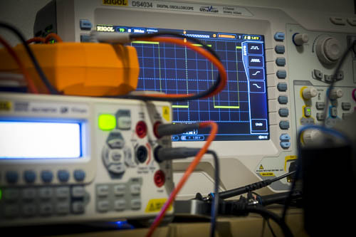
The oscilloscope is for the electronics what a good debugger is to a developer or a reverse engineer: a must-have. My first digital oscilloscope was a Mixed Signal Oscilloscope (MSO). But I was a bit disappointed of the logic analyzer and honestly I had no use of having both the analog and the digital signals on the same tiny screen. Therefore I changed it to a Rigol DS4034 oscilloscope. There was recently a sale and it came with the full bundle of options (all protocol decoders, advanced trigger options, and a bandwidth upgrade included) for free which makes it actually a Rigol DS4054 with 500MHz bandwidth. It has a very wide screen and while 2 channels would cover most of my need, there are times when 4 channels are necessary. Unfortunately, the software Rigol provides is not the same quality as their scopes: even with a 100Mbit/s Ethernet link, the UI is not fluid at all. It’s enough to make high quality screenshots without using a USB key but it’s unusable to make video or even control your scope in real time actually. An alternative software called Rigol UltraVision Utilities is available for free on the EEVblog forum and is much better than the official software. But the refresh rate is still not enough for good videos so I may consider in the future using the VGA output of the scope and plug it into a USB capture card connected to the NUC.
An oscilloscope is not enough though; you also need multimeters. And yes, I’ve written that in plurals because you may think about having 2 multimeters: one for measuring the current and the other one for the voltage for example. I’m using a Rigol DM3068 bench multimeter. It has a superb accuracy (6½ digits), covers great ranges of measurements and provides 4 terminal measurements if needed for a reasonable price. The only bad thing about it is that the continuity tester is really slow (i.e. the time between you probing a circuit and hearing the multimeter emitting a beep is long). For my second multimeter I chose a handheld model, an Agilent U1273AX which is a really good piece of gear. Of course, as you would expect if you’ve followed my philosophy when it comes to choosing equipment, I also bought the infrared to USB cable to stream the results back to the NUC.
Nowadays most the electronic world and protocols we can see on a given device are digital and to have a closer look at those, we need a logic analyzer. Like many others, I picked a Saleae Logic one, more precisely the Pro 16 model. Pros are that it simply streams the samples to the computer, it does that over USB3, can sample at up to 100MHz, and has an SDK to allow you to write your own decoder. The main drawback for me is that the samples have to be buffered on the computer and only when you stop capturing you can see them on screen and use decoders. I would prefer to have a “real-time” option here. Also the 100MHz sampling frequency can be an issue when the bus you are looking at goes above 50MHz due to Nyquist limit.
Finally, because I also do some electronic repairs, I added to the lab a programmable electronic load. This allows me to easily test power rails which are usually the first thing to fail on a device, by setting constant current, constant voltage, constant resistance or constant power mode. Very handy to test those cheap power adaptors. Mine is a BK Precision 8601, connected to the NUC over USB.
Powering
Should you be experimenting, prototyping or analyzing an equipment, you will need to power the device in a long term, reliable way. And for that you will need a bench power supply. Mine is a Rigol DP832A that I haven’t chosen for it’s cheesy colors on the front panel but for its high precision.
To complement my setup I also added last year an arbitrary waveform function generator, or ArbGen, a Rigol DG1062Z. I kept it with the native 8Mpts memory even though it has physically 16Mpts memory inside and can be unlocked through a software license upgrade. But I’m not using it to generate complex signals at the moment therefore 8Mpts is plenty enough.
Prototyping, debugging, reverse engineering
Another essential piece of equipment that you will need are breadboards. They allow you to quickly prototype something without soldering anything. And to be complete here, you will also need jumper cables here. Personally I bought fairly expensive ones from Schmartboard but they are more durable than the cheap alternatives which tend to break easily. I have an assortment of male-male, male-female and female-female cables.
To easily interface with any device, I also have a bunch of Teensy 3.2. I just love their form factor and they are very powerful: with overclocking, the Teensy 3.2 can go at 96MHz and it embeds a DSP for complex math computation! I also have a RaspberryPi 2.
If you have read my previous articles or if you follow me on Twitter, you should already know that I also have most of the boards derived from the GoodFET project: GoodFET, FaceDancer (USB), GoodThopter (CAN bus) and ApiMote (Zigbee).
I also have a bunch of FTDI development modules such as the FT2232H, FT4232H and UM232H. They can be used to dump NAND memory, quickly interface with serials protocols such as RS232 or RS485 and also act as a fairly fast (~20MHz) JTAG interface that is compatible with OpenOCD. The smaller module even comes in a breadboard-friendly format.
To deal with (E)EPROMs and/or flash memory chips I have a TNM5000 with all the adapters, including the optional TSOP56 for NOR flash that I had to buy separately. I also have a PICkit2 and a PICkit3. The main reason about having both is that the PICkit2 is compatible with Linux. But newer Microchip MCUs require a PICkit3.
When it comes to RFID, I have a Proxmark3 from RiscCorp that I recently upgraded to Proxmark3 RDV2. It comes with much better antennas (sometimes they are a bit too good actually) and in a nicer form factor without the stupid Hirose to USB cable. Also it has a more modern micro-USB plug instead of a mini-USB.
For radio frequency investigations, I have bladeRF x115 since I was part of the Kickstarter campaign with its optional transverter XB-200 for lower frequencies. But that’s not a surprise considering that I am the author and maintainer of the SDRSharp plugin for it.
I also have a bunch of Chipcon/Texas Instrument dongles: CC1111EMK, CC2511EMK and CC2540EMK. They are very handy to quickly deal with some sub-GHz protocol with RFcat or to sniff at Bluetooth LE packets. I also have the complementary Chipcon debugger which allows in conjunction with SmartRF Studio to experiment easily and reflash the dongles with the RFcat firmware (but a GoodFET would have been enough for that purpose).
In order to deal more specifically with Bluetooth and Bluetooth LE protocols, I have an Ubertooth One dongle
I also participated at the crowd funding campaign of Chipwhisperer but I haven’t got the time yet to go through all the documentation and tutorials to use it effectively.
And for more high speed or complex protocols, I have a Terasic Altera Cyclone IV FPGA development kit which allows me through its extensive set of mezzanine boards and GPIOs to interface with pretty much everything provided I spend enough time writing Verilog/VHDL for that.
Conclusion
It makes a quite long article and I hesitated to cut it into several parts but as some choices I made are somehow linked between the categories, I thought it would make more sense to have everything in one single article. I also hope that it will be helpful to some of you and don’t hesitate to tell me in the comments section.
0 notes
Text
HR-MP5 Encoder Fix
Aloha, fellow prisoners of planet Earth. Well, in this age of Drumpf and Brexit and all the other nonsense, I sure do feel like a prisoner sometimes. If I could get them to stop the planet and let me off, I damn well would. But I digress..
I’ve had a Sony HR-MP5 collecting dust here for maybe more than a year now. I was using it quite a bit before I moved all the gear into the current ‘lab’ room, but it got set in a pile of half-rack gear and forgotten. It didn’t help that I went through a pedal-crazy phase during which I unloaded ALL of my rack-mount effects processors. Some of the devices I parted with include an Eventide H3000-D/SX (with the Kitchen Sink upgrade), a Lexicon PCM-80, a Lexicon MPX-1, a variety of Sony DPS units, and so on. Some of you may be saying “What? You got rid of a freaking H-3000? PCM-80? FOR PEDALS? Have you gone completely mad?!” Well, not any more mad than I already am. See, the thing about the pedals is that technology has developed/progressed in such a way that pedals are now capable of simply amazing effects, and at staggering quality. The pedals I favor at the moment are: TC Electronics Trinity, T2 and Nova Modulator; Hotone Xtomp, Red Panda Particle, Strymon Timeline and an Eventide Space. The only two rack effects I still have are the HR-MP5 and an AKAI EX90R. Seriously, the Space is easily just as good if not better than the H3000. Obviously it has far, far fewer algorithms but for what it does have, it is SO good. Right.
So back to the HR-MP5. The main reason I haven’t been using it is because the encoder is jumpy to the point of being unusable. And, since the encoder is the only way to recall programs, well... Yeah of course I could send MIDI program change messages, but since I have a real distaste for using a computer as part of my setup, it’s more of a bother than it’s worth. So the poor thing sat under an FB-01 for far too long, until tonight, when I decided spur-of-the-moment style to open the fucker up and see if I couldn’t fix the encoder.
I posted here about a Novation Nova II X that I acquired, I’m sure. It had two jumpy encoders, so I disassembled them, cleaned the lubricant out (it had started to solidify), and after it was all back together waddaya know it worked good as new. How much harder could it be with the HR? Well...
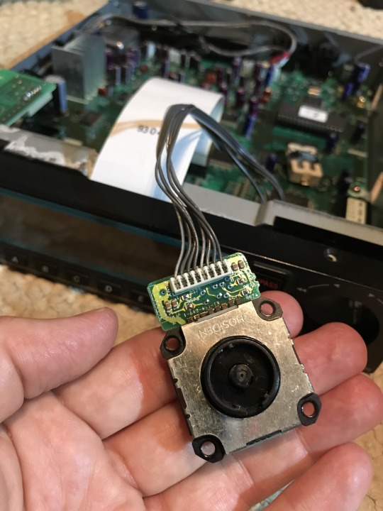
Here’s the encoder housing. The center knob is the actual encoder part, the outside black ring is the business end of the jog dial. Not visible in the photo is the underside of the unit. There are 8 pins that needed to be desoldered from the PCB, then four small tabs that thad to be straightened out before the metal part visible in the photo could be carefully lifted off. There were three latch-type snaps that held the housing onto the plastic body of the assembly, and those just needed some gentle prying up before they came right off.The parts of the assembly then were easily removed. There was the jog dial part, a grey disc-like thing with tracks for the jog dial, and then a large black skinny thing that was the knob for the encoder. They all have to be oriented in a certain way, so I was careful to set them down in a way that I’d know which end was up and could easily reassemble the thing when the time came to do so. Cleaning the lubricant out was simple. Q-tip and denatured alcohol. I also gently tweaked the wiper elements on both the encoder and the jog dial so they’d make proper contact. Then it was just a matter of careful reassembly, re-soldering, and testing. Worked perfectly. 20-minute job. Now I’ve got the JU-06 run through it and am easily recreating the sounds and moods from the following video:
youtube
He has the Juno-60 on Manual the whole time, so copying the patches is super easy. The JU-06 nails this sound too, almost flawlessly (the only thing lacking is polyphony). Such a lush, dreamy atmosphere. Nails the experience I had running a Juno-6 though the HR (when I still had the Juno-6).
And now a shameless plug for a project of mine. One of my alter egos is a project that I call Chandlerism, which exclusively uses old Yamaha four-track cassette multitrack recorders and homemade loop tapes to create ambient/drone atmospheric stuff. I haven’t really been in a creative state of mind since the new school (work) year started in April, thanks to being just totally slammed with a brutal schedule (I have to teach 27 classes a week, so I have basically zero time to plan or look back on lessons, or do much of anything else actually). In any case, why not check it out, you might dig it.
https://chandlerism.bandcamp.com
See ya.
0 notes
Last Seen Blogs

uenchsv
Unbetitelt

newtxtinaforever
Nothing But Newtina

historyhero
The world war history

strongcatholicfaith
My Journey

positively-negative09
depressing sex and wholesome murder