#uln2003
Photo
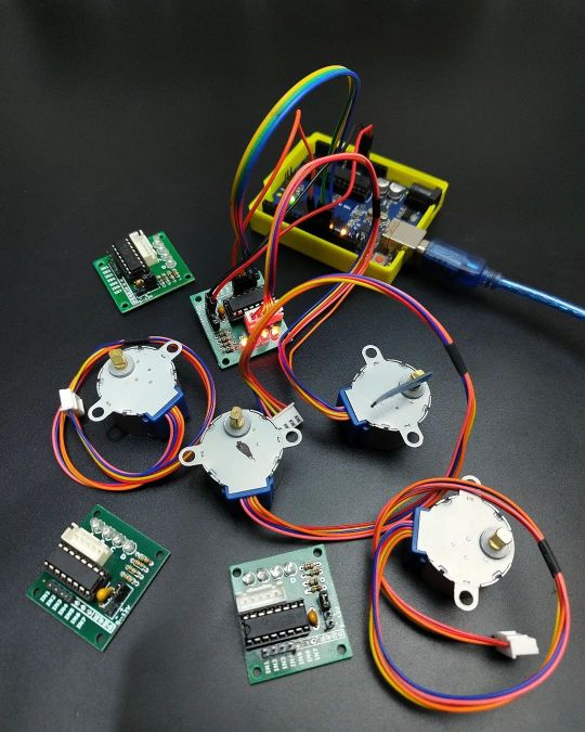
controlling 28BYJ-48 stepper motor using ULN2003 driver and Arduino Uno #arduino #steppermotor #robotics #stepper #electronicsreel #electronicsprojects #motors #diy #uln2003 #automation #byj #arduino #programming #circuit https://www.instagram.com/p/CnuGjUwLqbN/?igshid=NGJjMDIxMWI=
#arduino#steppermotor#robotics#stepper#electronicsreel#electronicsprojects#motors#diy#uln2003#automation#byj#programming#circuit
2 notes
·
View notes
Text
Build a Mini 3D Printer
Introduction: Even in the age of digital photography, there is still a certain charm to holding a physical print.
Taking it a step further, what if he could create three-dimensional objects from digital images? With a little creativity and ingenuity, you can turn your Instax Mini Link 2 printer into a mini 3D printer.
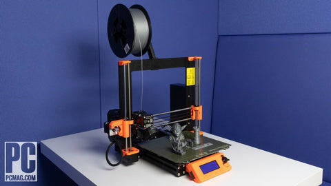
by: PCMAG.com
In this step-by-step guide, learn how to repurpose this popular portable photo printer to bring his 2D photos to life in 3D. Materials needed: Instax Mini Link 2 printer Arduino board (e.g. Arduino Uno) Stepper motor (28BYJ- 8 or similar) Motor driver module (ULN2003 or equivalent) 3D printing software (such as PrusaSlicer) Filament (PLA recommended) 3D modeling software (such as Tinker ad) Power supply (5V, USB compatible) USB cable
Step 1: Prepare your Instax Mini Link 2 printer First, carefully disassemble the Instax Mini Link 2 printer. Remove the outer case, being careful not to damage the main circuit board and printing mechanism. Make a note of the cables and connectors as you will need them later.

Step 2: Connect the Arduino Board Connect your Arduino board to your computer using a USB cable. Install the required drivers, if necessary. Next, upload the firmware required to control the stepping motor. You can find pre-built code and libraries online to simplify this process.

Step 3: Wire the Stepper Motor Connect the stepper motor to the motor driver module according to the pin configuration given in the datasheet. A motor driver acts as an interface between the Arduino and the stepper motor, controlling its rotation and position.
Read more
1 note
·
View note
Text
6-channel speaker selector
At the beginning of 2018, we developed the first version of the 6-channel speaker selector using PIC16F88 MCU and ULN2803 Darlington transistor array. In this new design, we redesign it with low-cost MCU and Darlington transistor arrays. This design also provides the same functionality as the 6-channel speaker selector switch we designed earlier.
This new speaker selector uses STC15W201 MCU. This MCU is a low-cost 8051 MCU designed by STC micro. At the time of this writing, the STC15W201 can obtain for less than US$ 0.8. To drive the seven segments and to control the relays, this design uses the popular 74HC595 8-bit shift register ICs.

To select each speaker channel, we use pair of 12V DPDT relays. These relays interface to 74HC595 through a ULN2001D 3-channel Darlington transistor array IC. This 3-channel Darlington driver IC is functionally equivalent to the famous 8-channel ULN2003 IC. This ULN2001D version is an 8-pin IC and is available in both DIP-8 and SOP-8 packages.
This new board is designed to work with a 12V DC power supply and in our prototype build, we use a 12V/5A SMPS unit to power the whole system.
To get the optimal results with this circuit, use an Omron G2R-2-12DC or an equivalent type of relay with a coil current lower than 100mA.
The firmware of the STC15W201S is developed using SDCC. To flash the MCU, we use stcgal. Thanks to the built-in bootloader, we can program this MCU using a generally available 5V USB to UART module/dongle.
The complete build process of the speaker selector is shown in the video below:
youtube
The functionality of the firmware is almost identical to the old PIC16F88 firmware. After powering up the system, the active speaker channel is displayed on the seven-segment display. To switch to a different speaker channel, press the button repeatedly with short intervals.
To mute or disconnect the current speaker channel, press and hold the same button for more than 3 seconds.
As described above, all functions of this circuit can be the control using a single push switch.

The PCBWay sponsored this project. PCBWay offers high-quality PCB manufacturing and assembling services. Also, they offer CNC and 3D printing services. The Speaker selector PCB is available to order from PCBWay. Check out the PCBWay website for its manufacturing capabilities and pricing.
This project is an open-source hardware project. All its design files, schematics, and firmware source codes are available at Github.com.
The PCB design, schematic, and other design files of this project are covered with a CERN-OHL-W 2.0 license. Firmware source code is released under the terms of the MIT license.
#audio#8051#STC15W201#ULN2001D#74HC595#switch#speaker-selector#electronic-switch#AMS1117-5.0#PCBWay#prototype#SDCC#Relay#STC#Youtube
0 notes
Text
ULN2003 IC DIP 16 Pin Transistor Arrays
ULN2003 IC Price in India || ULN2003 IC Buy || ULN2003 IC DIP 16 Pin Transistor Arrays.
TheULN2003devices have a 10.5-kΩ series base resistor to allowoperation directly fromCMOS devices that use supply voltages of 6 V to 15 V. The required input current of the ULx2004A device is below that of the ULN2003A devices, and the required voltage is less than that required by the ULN2002A device.
The ULN2002A device is designed specifically for use with 14-V to 25-V PMOS devices. Each input of this device has a Zener diode and resistor in series to control the input current to a safe limit. The ULx2003A devices have a 2.7-kΩ series base resistor for each Darlington pair for operation directly with TTL or 5-V CMOS devices.
Features:
500-mA-Rated Collector Current (Single Output)
High-Voltage Outputs: 50 V
Output Clamp Diodes
Inputs Compatible With Various Types of Logic
Relay-Driver Applications
Applications:
Relay Drivers
Stepper and DC Brushed Motor Drivers
Lamp Drivers
Display Drivers (LED and Gas Discharge)
Line Drivers
Logic Buffers
Inverter
ULN2003 Pin Configuration and Functions:
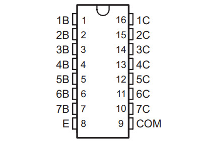
Download ULN2003 Datasheet PDF
0 notes
Text
Small servo motor arduino

Small servo motor arduino driver#
In fact, you can even stack multiple Motor HATs, up to 32 of them, for controlling up to 64 stepper motors or 128 DC motors (or a mix of the two) - just remember to purchase and solder in a stacking header instead of the one we include. Only two pins (SDA & SCL) are required to drive the multiple motors, and since it's I2C you can also connect any other I2C devices or HATs to the same pins. This chip handles all the motor and speed controls over I2C.
Small servo motor arduino driver#
Since the Raspberry Pi does not have a lot of PWM pins, we use a fully-dedicated PWM driver chip onboard to both control motor direction and speed. Raspberry Pi and motors are not included. This Raspberry Pi add-on is perfect for any motion project as it can drive up to 4 DC or 2 Stepper motors with full PWM speed control. Let your robotic dreams come true with the new DC Stepper Motor HAT from Adafruit. How to control a ULN2003 stepper motor with Raspberry Pi Suitable for microcontroller developmentĭimensions: 1.38 in x 1.18 in x 0.39 in (3.5 cm x 3.0 cm x 1.0 cm) High quality stepper motor with ULN2003 driver The board also comes with an ON/OFF jumper to isolate power to the stepper Motor. They provide a nice visual when stepping. The board has four LEDs that show activity on the four control input lines (to indicate stepping state). Four out of seven pairs are used on this board. The ULN2003 is one of the most common motor driver ICs, consisting of an array of 7 Darlington transistor pairs, each pair is capable of driving loads of up to 500mA and 50V. The power consumption of the motor is around 240mA. In addition, the motor has a 1/64 reduction gear set. That means there are 32 steps per revolution (360°/11.25° = 32). The 28BYJ-48 motor runs in full step mode, each step corresponds to a rotation of 11.25°. The maximum speed for a 28byj-48 stepper motor is roughly 10-15 rpm at 5 V.
0 notes
Text
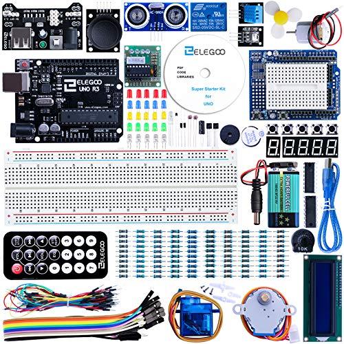
ELEGOO UNO Project Super Starter Kit with Tutorial and UNO R3 Compatible with Arduino IDE
ELEGOO UNO Project Super Starter Kit with Tutorial and UNO R3 Compatible with Arduino IDE
Price: (as of – Details)
Component listing: 1pcs UNO R3 Controller Board 1pcs LCD1602 Module ( with pin header) 1pcs Breadboard Expansion Board 1pcs Power Supply Module WARNING: Pls. do not use the voltage higher than 9V 1pcs Joystick Module 1pcs IR Receiver 1pcs Servo Motor (SG90) 1pcs Stepper Motor 1pcs ULN2003 Stepper Motor Driver Board 1pcs Ultrasonic Sensor 1pcs DHT11 Temperature and…
View On WordPress
0 notes
Photo
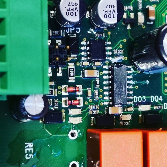
#elektroniikka #ilmastointikoneenkortti #vikaavikaa #takuuloppu #justiinsa #uln2003 #smd #pintaliitos #teemukorjaa #mahotontehtävä #paskaamyivät #vuoristosairaala #sähkömies #sähköasentaja #esilämmitys #ohjaus #t_pirttinen (paikassa Seinäjoen Keskussairaala) https://www.instagram.com/p/B9ST7W7jKz2/?igshid=1iygha46bx5p
#elektroniikka#ilmastointikoneenkortti#vikaavikaa#takuuloppu#justiinsa#uln2003#smd#pintaliitos#teemukorjaa#mahotontehtävä#paskaamyivät#vuoristosairaala#sähkömies#sähköasentaja#esilämmitys#ohjaus#t_pirttinen
0 notes
Text
[Amazon]ステッピングモーターが届いたよ
前に買ったステッピングモーターが届きました ていうかすっかり忘れてたw 興味本位に買ってみました [amazonjs asin=”B010RYH74U” locale=”JP” title=”HiLetgo 5V ステッピングモータ+ ULN2003ドライバーボード セット 並行輸入品”] 明日がテストとか課題の提出日とかの関係で解説っぽいことはまた今度やりますが、ステッピングモーターはパルスを送るたび回転するモーターです。現在の状態からの角度が細かく出来るとか (more…)
View On WordPress
0 notes
Text
Assignment 3 Iteration One
The first iteration of my code basically just runs the stepper motor (28BYJ-48) at a constant speed of 500 steps per second. The stepper motor is in half step mode, so one full revolution takes 4096 steps. So it takes about 8 seconds or so for the stepper motor to make a full revolution. I’m using the AccelStepper library by Mike McCauley, as it allows for easy control of the stepper motor as well as acceleration and deceleration. I’ve connected the stepper motor to a 9V battery as while the stepper motor can be directly powered from the Arduino 5V output, this can lead to the Arduino getting damaged if the stepper motor draws too much current. However, due to the ULN2003 driver board, this makes the process much easier, and lessens the amount of components that need to be used. Each stepper motor takes up 4 output pins, so with the 2 stepper motors I’ll be using, I’ll have 6 output pins for the rest of my components. I’ll have to look into how to fit everything in. In my next iteration I’ll be looking at how to move the stepper motor in different directions.
0 notes
Text
Today's delivery: ULN2003
Inquiry: [email protected]
Find more: www.seektronics.com

#STMicroelectronics#components#semiconductor#electronics#electronicshop#electroniccomponents#electronicscomponents#electronicparts#icchips#electroniccomponent#chipshortage#billofmaterials
0 notes
Text
Holo Clock is a novel 3D-printed clock that tells time using a pair of rings
Simply looking at a traditional analog clock sitting on a wall somewhere got pretty boring for one Instructables user who goes by saulemmetquinn, which is partially why they wanted to create a novel design instead. Their device uses almost entirely 3D-printed components that come together to form the “Holo Clock,” since it seems holographic with its floating minute and hour hands.
The Holo Clock project started with a surprisingly complex design in CAD software. There are two rings that are lined with teeth that sit stacked horizontally. The back ring is the minute hand, and because it is moved almost directly by the stepper motor, it spins more quickly. The hour hand is driven by a set of gears that reduce the output of the minute hand’s cogs by a factor of 60, thus making it turn at the correct rate.
The electronics for the clock are extremely simple. It uses an Arduino Uno with a set of four output wires, along with power and ground, to control a ULN2003 stepper motor driver. This in turn outputs current to a generic 5V stepper motor that spins the first drive gear at a known, precise rate for consistent timing. Likewise, the code is also straightforward, as all it must do is step the motor a certain amount depending on how many steps are left within the loop.
You can read more about the project in saulemmetquinn’s tutorial, which was recently recognized as a runner-up in the Instructables Arduino Contest.
The post Holo Clock is a novel 3D-printed clock that tells time using a pair of rings appeared first on Arduino Blog.
Holo Clock is a novel 3D-printed clock that tells time using a pair of rings was originally published on PlanetArduino
0 notes
Text
5pcs Five-wire four-phase / stepper motor driver board / driver board (ULN2003) / test board
5pcs Five-wire four-phase / stepper motor driver board / driver board (ULN2003) / test board

5pcs Five-wire four-phase / stepper motor driver board / driver board (ULN2003) / test board
Price
5
Catch me HERE
0 notes
Text
Five-wire four-phase stepper motor driver board module / ULN2003 test board compatible
Five-wire four-phase stepper motor driver board module / ULN2003 test board compatible

Five-wire four-phase stepper motor driver board module / ULN2003 test board compatible
Price
1
Catch me HERE
0 notes
Last Seen Blogs

iamjusthereforthefreefood
Freddie Mercury is Braver Than the US Marines

lookvideos-blog-blog
Look Videos

signaturetouchllc-blog
Untitled

emilyjean-stone
reputation (Taylor's version)

aspercarlotti
AsPerCarlotti