
Last Seen Blogs

monsterbones
Monster Bones
monsterbones
Monster Bones

emoedgyvampire
EmoEdgyVampire

laylasshiftingtonight
layla

breezysunday
SHALLOW MIKU
Text
Upgrading the Sample Planetary Rotation System

One of the characteristics of a suitable thin film is the degree of uniformity of the deposited layer. Rotation of the substrate during coating is one of the most effective ways to increase the uniformity of thin film deposited in the Physical Vapor Deposition (PVD) method. The effectiveness of substrate rotation in improving the uniformity of the deposited thin film depends on the geometry of the substrate and how it rotates during the coating process. For example, in the case of substrates with a flat geometric shape (such as a disk), rotation about an axis perpendicular to the surface of the substrate is sufficient to create a uniform layer on it.
https://bit.ly/2MDB3Nk
However, for more complex geometric substrates that have uneven surfaces in terms of height, it is necessary to rotate the sample around other axes so that all the hidden angles of the substrate are covered and avoid shadowing of one area on the other area. This type of rotation is called Planetary Rotation. Planetary rotation (in three directions x, y, z) causes the pores of the porous specimens to be well covered. For example, when a porous rock is to be observed with an electron microscope, the inside of the cavities should also be covered with a thin layer of gold, and this will be possible by using a planetary sample rotator.
Most models of the vacuum deposition systems manufactured by VacCoat Ltd. such as Desk Sputter Coater (DSR1), Desk Carbon Coater (DCR), High Vacuum Sputter Coater DST1-170 and High Vacuum Carbon Coater (DCT), all known as SEM coaters, are equipped with a planetary rotation option. Recently, the researchers and experts of this company have started to upgrade the planetary rotating system of their product. Smoother rotation, more robustness, and easier installation are the features of this new sample planetary rotation system.
All sample holders installed on the products of VacCoat Ltd. can be designed and delivered according to the customer’s needs. Replacing and placing sample holders on these devices is very simple and the user is easily able to do it. For more information about the products of VacCoat Ltd., refer to its website.
https://bit.ly/2MDB3Nk
0 notes
Video
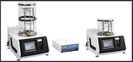
Setup & Installation Guide of VacCoat Desk Sputter and Carbon Coater System model DSCR.
Dear Vaccoat customer, thanks a lot for choosing our products for buying and we hope you enjoy working with this system.
This short video shows you how to easily unpack and install the DSCR coater in your lab. Please follow it step by step and study the user manual. If you need more help, please contact the aftersales service of company or our agents in your country.
The System is designed to protect itself against the wrong commands of the user. Its software is very user friendly and users learn how to work with the system in a short time.
We tried to use the packaging with the maximum protection against the issues which usually happen in shipment process. Please keep the box and don’t throw it away during the warranty period. https://youtu.be/pdlWxGapTN4
0 notes
Photo

New Blog
Getter Pumps | High Vacuum Pumps
There has also been a Gettering mechanism, which has been a pumping method, since vacuum technology came into being. Historically, the first use of this method was in the early stages of making electron tubes.
https://www.linkedin.com/pulse/getter-pumps-high-vacu..
https://bit.ly/2YEGE8q
#vaccum#vacuumpumps #science
0 notes
Photo
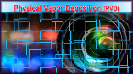
New Blog: Physical Vapor Deposition (PVD)
Physical Vapor Deposition (PVD) is a set of vacuum deposition methods in which a solid material vaporizes in a vacuum environment and is deposit on the substrate as a thin film....https://bit.ly/3pCAYrm
#vapor #depositions #vacuum
0 notes
Photo

New Blog
Outgassing Phenomenon | Outgassing in Vacuum Deposition.
In high vacuum systems, the most important source of problem in the vacuum process is the gases that are expelled from the surfaces of objects in the vacuum chamber, which is called outgassing.... continued at https://bit.ly/3bNtBJF
#outgassing #vacuum #sceince #blogcontent
0 notes
Photo

We are pleased to announce the news of a new collaboration between VacCoat and Japanese Meiwafosis. We have signed an exclusive sales representative agreement with Meiwafosis Co. to promote VacCoat Ltd. products in the Japanese markets.
Read more here https://bit.ly/35jWZ6f
0 notes
Photo
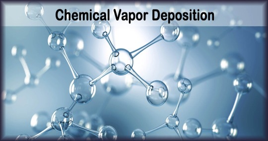
Chemical Vapor Deposition (CVD)
Chemical Vapor Deposition (CVD) is a chemical process used to create layers with different applications on different surfaces. In this deposition method, the desired surface(substrate) is exposed to the vapor of one or more chemicals.
https://bit.ly/3aUGCkc
0 notes
Text
Happy New Year from all at VacCoat

https://vaccoat.com
#new year#happynewyear#new year 2021#stay safe#vacuum#vacuum technology#vacuum coating#Vacuum System
0 notes
Text
Hydrophilicity and Hydrophobicity: Hydrophilicity of Deposited Carbon Thin Film

Hydrophilicity of the Deposited Carbon Thin Film
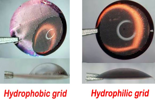
The hydrophilicity or hydrophobicity of different surfaces depends on their chemical composition and structural geometry. This feature of the surfaces plays a significant role in our nature and daily life. If water beads up into droplets and does not spread evenly across the surface, is hydrophobic. On hydrophobic surfaces, the contact angle of water droplets with the surface is large. In contrast, if a drop of water that is placed on the surface is evenly distributed and has a small contact angle with the surface, it is called a hydrophilic surface.
Surface modification with low-surface-energy materials is a typical technique to control over the hydrophilicity of solids. For example, using nano-structured polymers, surfaces with a high degree of hydrophobicity are produced. Carbon is one of the materials that has been considered in the microelectronics industry due to its environmental friendliness and good economic efficiency. Both the carbon thin film deposited by evaporation from a carbon fiber or rod, and the carbon thin film deposited by sputtering from a graphite target, is amorphous.
Amorphous carbon layer has hydrophobic properties that can be increased or decreased by different methods according to the intended application. One of the applications of the carbon thin is use in the preparation of Transmission Electron Microscope(TEM) grids. In this case, the hydrophobicity of the carbon layer needs to be converted to hydrophilicity. Plasma is used for this purpose. In most cases, surface hydrophilicity increases due to the presence of hydrophilic groups such as hydroxyl(OH), carboxyl(COOH) and carbonyl(CO) on the surface.
https://bit.ly/3kXtKMn
Oxygen plasma enters into a chemical reaction with the surface, allowing the adsorption of functional groups that alter the surface properties. However, argon plasma does not react chemically with the surface and depending on the plasma energy, removes surface contaminants and increases the surface roughness. This change in surface roughness changes the surface energy level, which changes the surface hydrophilicity.
Devices used to prepare TEM grids usually, in addition to the possibility of carbon deposition, also allow the use of plasma to increase the hydrophilicity of the deposited carbon thin film. A number of different models of VacCoat Ltd. devices allow the user to coat carbon thin film, such as the DSCR, DSCT, DCR, and DCT models. In the new versions of these models, the Plasma Cleaner feature is to be added to complete the efficiency of these models in the process of preparing TEM grids.
https://lnkd.in/d4Ej8-K
In addition, using Plasma Cleaner before applying the deposition improves the quality of the deposited layer and increases its adhesion to the substrate. The design and manufacture of Plasma Cleaner has been done on the mentioned models and the initial tests show a satisfactory result. It should be noted that the DST1-300, DST3 and DST3-T models were previously equipped with Plasma Cleaner and have been used by many users. For more information about the devices manufactured by VacCoat Ltd., refer to the internet address.
https://bit.ly/3kXtKMn
https://lnkd.in/d4Ej8-K
#nano#nanotechnology#nanoscience#water#vacuum#vacuum coating#deposition#evaporation#sputtering#sputter coater#hydrophilic#hydrophobic
0 notes
Text
Sputtering Process | Sputtering Deposition Method
In terms of physics, Sputtering is a phenomenon in which energetic particles of plasma or gas hit the surface of a solid and microscopic particles are separated from it. This phenomenon occurs naturally in outer space and can cause unwanted surface wear in high precision conditions. Creating or removing nanometer layers from materials has many applications in science and industry. Deposition of nanometer layers on optical devices, semiconductors and nanotechnology products or etching of nanometer layers is widely used in the study and application of analytical techniques for a variety of applications.
Due to the collision of high-energy ions with the target material atoms, momentum transfer occurs between them. These ions, called incident ions, cause a series of collision cascades on the surface of the target. Sometimes these successive collisions cause the ions to travel long distances and lose their energy. If the ion energy at the time of reaching the target surface is greater than the bonding energy between the atoms of the target material, the collided atom separates from the target material. This phenomenon is called Sputtering.
Sputter Yield
The energy of sputtered atoms varies widely, and usually the energy of these atoms is more than tens of electron volts. Approximately one percent of the ions that hit the surface of the target material have a ballistic impact and return to the substrate, causing Resputtering. The average number of atoms separated from the surface of the target material by the collision of each ion is called the Sputter Yield.
The sputter yield depends on many factors, such as:
The angle at which the ions strike the surface of the target material
The amount of ion energy during the collision
The weight of the ions
The weight of the atoms of the target material
The binding energy between the atoms of the target material
If the structure of the target material is crystalline, the orientation of the crystal axis relative to the surface is also an important factor in the sputtering yield.
https://bit.ly/3kkj5e4
Deposition
One of the applications of sputtering phenomenon is Deposition. Deposition using sputtering is a method of creating thin films of a few nanometers to a few micrometers on the desired substrate. In this process, the atoms separated from the surface of the target material are gaseous. These thermodynamically unstable atoms tend to be on a surface in a vacuum chamber. The atoms on the substrate which form a layer with a few nanometers to a few micrometers thick, called a Thin Film.
Physical Vacuum Deposition Method
Deposition using the sputtering phenomenon is a physical vacuum deposition method(Physical Vapor Deposition(PVD)). PVD is a set of deposition methods in which the material enters the vapor phase from the dense state and returns to the dense phase as a thin film. These vacuum deposition methods include three stages:
Evaporation of the target material
Transfer of vapor from the target material to the substrate
Formation of a thin film on the substrate with accumulation of vapor of the target material
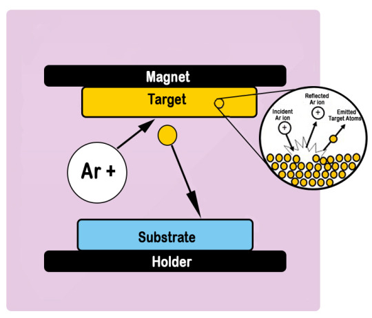
Sputtering Process
In order to deposition process using sputtering, ions need to be fired at the target material in the plasma medium. The gas to be used in the sputtering process must have two properties: first that its atomic weight must be such that it can affect the atom of the target material, and second that it must not enter into a chemical reaction with the target material. According to the mentioned cases, the gases used in the Sputtering Process are from the group of noble gases in the end rows of the periodic table(Argon, Xenon, etc.). Argon gas is the most common gas used in this process.
Gaseous plasma is a dynamic environment in which neutral gas atoms, ions, electrons and photons are in near equilibrium. To feed the plasma and compensate for the energy that is transferred from the plasma to the surrounding area, it is necessary to use an energy source(for example, DC or RF power supply) in order to maintain the plasma. In order to do the sputtering deposition, plasma is formed by injecting a noble gas(usually argon) into the chamber which is vacuumed until a certain pressure(maximum 0.1 Torr) and applying DC or RF voltage(depending on the target material).
Diode Sputtering
The free electrons in the plasma are immediately removed from the negative potential electrode(cathode). These accelerating electrons collide with neutral gas atoms(argon) in their path, causing the electrons in the shell of these atoms to separate. As a result, the gas atoms become positive ions and accelerate towards the cathode, causing the sputtering phenomenon. In plasma, some free electrons find their way back to the last electron layer of gas ions and return the gas atoms to their ground state. The return of the atom from the high energy level to the ground state leads to the release of energy in the form of photons, and these photons are the reason for the glowing of the plasma. This mechanism is called Diode Sputtering. One of the problems with this method is that its coating rate is low and it takes longer to do the coating, which causes the target to heat up and damage its atomic structure.
Magnetron Sputtering Method
With the advent of magnetron sputtering method, the problems for diode sputtering were solved. By placing a number of magnets behind the cathode, the free electrons are trapped in the magnetic field of these magnets just near the target surface. These electrons do not reach the substrate like the diode sputtering method and do not bombard the substrate surface. The movement of these electrons in the path of the curve led by the magnetic field increases the probability of ionization of the neutral gas atoms many times over. Increasing the ions that hit the surface of the target increases the rate of deposition. Our products such as DSR1, DST1, and DST3 are equipped with magnets behind the cathode and perform magnetron sputtering.
https://lnkd.in/dTynUdi
Confocal Sputtering
If the deposition process is performed from several cathodes, the Confocal Sputtering Technique can be used. In this technique, the cathodes are arranged in a circular pattern with a focal point. By placing the substrate that rotates around its axis at or around the cathodes focal point, a layer is deposited that has a much better uniformity than the layer deposited using a cathode. Also if it is necessary to perform the deposition of several different materials(Simultaneously for alloying(co-sputtering) or asynchronous to create multi-layers), this technique is effective. Using this technique, a uniform layer can be obtained on a substrate with a diameter twice the diameter of the target. Also, for materials that have low sputtering yield, the deposition can be applied using several cathodes simultaneously at a higher speed. The triple cathode, sputter coating manufactured by VacCoat Ltd. in DST3-A and DST3-TA models, due to being equipped with three angled and focal cathodes, are able to perform confocal sputtering.
Reactive Sputtering
In this type of sputtering, the atoms separated from the target undergo a chemical reaction before being deposited on the substrate. The resulting deposited thin film will have a different composition than the target material composition. Chemical reaction occurs between atoms separated from the target and reactive gases(such as oxygen or nitrogen) that enter the vacuum chamber during the deposition process. By adjusting the amount of inlet gases and noble gas(argon) used in this process, a thin film with the desired composition and stoichiometry can be deposited. In various models of VacCoat Ltd. products such as DST1, DST3 and DSCR, one or more inlets are installed to allow enter the reactive gases such as oxygen to the vacuum chamber during the deposition process.
DC Sputtering
Different types of power supplies can be used for sputtering. The type of power supply suitable for each deposition process depends on the target material. DC Sputtering is suitable for metals and materials that are electrically conductive. The DC power supply used in this method is less complex and more controllable than other power supplies and has a lower manufacturing cost. This is why DC sputtering is the most popular sputtering method in terms of power supply. DSR1 device made by VacCoat Ltd. is a simple device that has a lower price than other models. This device is only capable of DC sputtering.
RF Sputtering
DC sputtering cannot be used if the target material is electrically non-conductive or has low electrical conductivity. As described in the previous sections, in the sputtering process, positive ions accelerate towards the target and cause the target atoms to be removed. If the electrical conductivity of the target material is low, a positive charge will accumulate on the surface of the target and prevent other positive ions from accelerating towards the target, thus the sputtering process will be stopped. With the RF power supply, in RF Sputtering, the polarity of the electrical potential changes with each periodic cycle, result in discharging the electrical charges accumulated on the target surface. Sputtering models DST1-300, DST3, DST3-T are equipped with RF power supply and impedance matching box and are able to do RF sputtering.
High Power Impulse Magnetron Sputtering(HIPIMS)
HIPIMS is a new Magnetron Sputtering Method that uses high power pulses to increase target ionization. Compared to conventional magnetron sputtering, this method ionized atoms reach the substrate with more energy, which increases the density and quality of the deposited thin film.
Various models of Vacuum Coating Systems manufactured by the VacCoat Ltd. perform sputtering deposition process. These devices are classified into different models depending on the ultimate pressure they can reach, the power supply used in them for the sputtering process, the number of cathodes, the dimensions of the vacuum chamber, and etc. For more information about the products of VacCoat Ltd., refer to our site.
https://bit.ly/3kkj5e4
https://lnkd.in/dTynUdi
#nano#nanotechnology#nanoscience#coatings#vacuum coatings#deposition#deposition method#sputtering#magnetron sputtering#rf sputtering#dc sputtering#pvd
0 notes
Text
Innovative News | Improved Desk Thermal Evaporator-DTT
https://vaccoat.com
Enhanced Uniformity of Thin Film Deposition in Thermal Deposition Process via Extended Deposition Chamber
Thermal evaporation deposition is one of the Physical Vapor Deposition(PVD) methods. In this method, the target material is placed inside thermal sources. These thermal sources are normally in form of Boat, Basket or Coil. The materials to be deposited are heated up, melted and evaporated by passing a high electric current through the terminal of evaporation sources. The vapor generated from the target material moves to the substrate and is deposited as a thin film with a thickness of a few nanometers to a few micrometers.
Boats or baskets are made of refractory metals such as tungsten, molybdenum or tantalum. Thermal evaporation deposition method is also called resistive evaporation. Standard distance between the substrate and the evaporation sources depends on the dimensions of the substrate. The larger the substrate size, the greater the distance from the evaporation source is needed to create better thickness uniformity. If the dimensions of the substrate are large enough that the entire surface of the substrate is not covered during the coating at the standard distance between the substrate and the evaporation sources, the substrate area covered can be increased by increasing this distance.
Deposition rates decreases with increase of distance between substrate and evaporation sources, but improves uniformity of deposited thin film. This also depends on level of vacuum in the chamber.
https://www.linkedin.com/pulse/enhanced-uniformity-th..
Improved Desk Thermal Evaporator-DTT
In the thermal evaporation system manufactured by Vac Coat Ltd., this distance is usually 20 to 25 cm. In order to produce a uniform thin film deposition on larger substrates, Vac Coat Ltd. has designed and added a new feature to its present DTT model thermal evaporation deposition system. The new version allows the user to increase the distance between the substrate to the evaporation sources up to 50 cm by installation of a second chamber.
For further information, please visit our website.
https://www.linkedin.com/pulse/enhanced-uniformity-th..
https://bit.ly/3ioYnIf
#coatingstechnology#nano#vacuum#vacuum_coating#vacuum_system#thermal_evaporator#thermal_evaporation#dtt
0 notes
Text
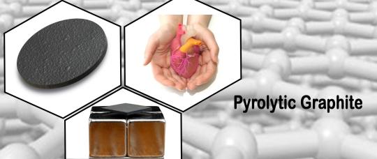
Pyrolytic Graphite
https://vaccoat.com
Pyrolytic graphite is a polycrystalline form of graphite that is deposited from the vapor phase by thermal decomposition of a simple hydrocarbon such as methane. Pyrolytic graphite is a man-made material similar to graphite, except that there are covalent bonds between its graphene layers. Graphite has a layered structure, and each carbon atom in each layer is bonded to three adjacent atoms. The atomic structure of graphite is a two-dimensional lattice of hexagons whose first and third layers exactly match each other, while the second layer is slightly displaced relative to these two layers.
https://www.diigo.com/user/vaccoat/b/565463365
Pyrolytic Graphite Structure
But the material deposited as pyrolytic graphite consists of layers of wavy, twisted plans composed of carbon atoms arranged in a hexagonal structure. These layers are mutually parallel to each other but rotated randomly around an axis perpendicular to the deposition plan(c axis). The layered structure, with strong intra-layer covalent bonds and weak electrostatic bonds(Van der Waals bonding) between the layers, leads to a high degree of anisotropy in all properties. It is inherently brittle at room temperature.
Properties
Due to the structural differences between pyrolytic graphite and conventional commercial graphite, different properties should be expected from this material. Thermal and electrical properties:
Linear thermal expansion
Thermal conductivity more than four times that of copper
Very high electrical resistance in the direction parallel to the deposition plan(perpendicular to C axis)
Very good thermal insulation
Very high electrical conductivity in the direction perpendicular to the deposition plan(parallel to the C axis)
From a mechanical point of view, the ultimate strength of pyrolytic graphite in stress, bending and compression increases significantly with increasing temperature. And magnetically, this material is a great diamagnetic material at room temperature(X = -4 × 10⁻⁴). Magnetic Levitation is a phenomenon that can be implemented using materials with high diamagnetic properties. This material is a suitable option for magnetic levitation due to its high diamagnetic properties.
Applications
Applications of pyrolytic graphite include the following:
Used in the rocket industry as a strong heating and cooling conductor
Used in nuclear reactors as a neutron modulator coating
Used in electronic devices as Heat sink
Used in the construction of grid structures in some high power vacuum lamps
Used in the automotive industry to create a certain amount of friction between two parts
Used in medical engineering industries, for example in the manufacture of artificial hearts, heart valves and artificial vessels due to the lack of rapid blood clot formation
https://bit.ly/33sCd2w
VacCoat
For the use of pyrolytic graphite in the thin film and semiconductor industry, this material can be deposited by sputtering method. Pyrolytic graphite is available in the market as a sputtering target. Ordinary graphite deposition using the sputtering method is difficult and time consuming due to the low sputtering yield of the graphite. Pyrolytic graphite targets are created using the CVD(Chemical Vapor Deposition) method and have a much higher density than graphite targets and less porosity. As a result, its sputtering yield is higher and outgassing phenomenon occurs quickly.
To create thin films of pyrolytic graphite, vacuum deposition systems made by VacCoat Ltd. can be used in different models that are able to do deposition by sputtering method. Products of VacCoat Ltd. that are able to perform sputtering are divided into different models according to the number of cathodes, type of power supply, chamber dimensions and ultimate vacuum. DST3, DST1-300, DSCT, DST3-T models are among the products that can deposit different materials by sputtering method. For more information about the products of this company, refer to the site.
https://lnkd.in/dnjmuqv
https://bit.ly/33sCd2w
0 notes
Text
Plasma Cleaning

https://diigo.com/0iefjj
Surface Cleaning Using Plasma in a Low Pressure Environment(vacuum) is an economical way to clean specimens uniformly and securely. Removal of contaminants from the studied substrates without affecting the overall properties of the material is one of the benefits of plasma surface cleaning method. Plasma is widely used in circuit industry, including cleaning the PCB board before coating and cleaning the lead frames during the packaging process. Plasma sample cleaning has significant advantages over other surface cleaning methods:
Applicable to a wide range of materials(metals, plastics, glass, ceramics, etc.)
Eco friendly. This method eliminates the need for hazardous chemical solvents, which saves considerable costs because it does not need to eliminate environmental hazards like other cleaning methods.
The solvents leave behind the cleaning process while the plasma cleaner is able to perform the cleaning process without any residual effect. This process destroys antioxidants, carbon residues, oils and various types of organic compounds.
Plasma surface cleaning is the best solution for microbial contamination. Many medical and manufacturing equipment depends on plasma because it is more effective than aggressive agents and organic solvents.
https://lnkd.in/dK8dQQj
Plasma Cleaning Process
Plasma surface cleaning is a process in which impurities and contaminants of the sample surface are removed by the creation of high-energy plasma from gaseous particles. Gases such as oxygen, air and a combination of air, nitrogen or hydrogen are used for this purpose. High frequency voltage(in the range of kHz to several MHz) is usually used to ionize these gases and generate plasma. Created plasma to clean the sample surface is usually formed in a vacuum medium(pressure about 1 milli bars). The plasma at atmospheric pressure is also used in some cases.
What is Plasma?
Plasma may be produced with DC or RF voltage. Low frequency sources are cheaper but less efficient. Choosing the appropriate source for surface cleaning application depends on a variety of factors, including cost. In order to properly select the source, the user must know which factors are more important to eliminate the contaminants in question: time, power, consumption gas, etc.
In plasma, gaseous atoms are excited and energized and often ionized. By returning atoms and molecules to their bases, they emit photons themselves. These photons give rise to the brightness and color of the plasma. Different gases lead to different colors of plasma, for example oxygen plasma emits light blue. Plasma active components include atoms, molecules, ions, electrons, free radicals and high-energy photons with low wavelengths in the UV range. Once formed, this compound encounters all exposed surfaces of plasma.
Types of Plasma
If the used gas in the plasma is oxygen, the created plasma is an economical, efficient and environmentally friendly means of thoroughly cleaning the studied surfaces. Ultraviolet energy in plasma is effective in breaking most of the organic bonds(C – H, C – C, C = C, C – O, C – N) of the surface contaminants and causes the separation of high molecular weight pollutants. The second stage of purification involves ionized ozone, free electrons, and oxygen particles created in the plasma medium, such as O2+, O2−, O3, O, O+, and O−. These particles react with organic contaminants and produce H2O, CO, CO2 and low molecular weight hydrocarbons. These compounds have relatively high vapor pressure and are evacuated from the chamber during the process. As a result of these reactions, the exposed surface to the plasma reaches an extremely clean state. This picture, shows the relative amount of carbon before and after plasma cleaning process.
https://bit.ly/3baml8p
If the sample is composed of oxidizing materials such as copper, inert gases such as argon or helium are used to plasma cleaning process. In these cases plasma-activated atoms and ions behave like molecular sandblasts instead of chemical reactions and can decompose organic contaminants. These pollutants evaporate during the process and are evacuated from the chamber. If hydrogen plasma is used in the surface cleaning process, it will be very suitable and effective for the removal of glass oxide or metals. Using different gaseous species(oxygen, argon, nitrogen, hydrogen, helium, etc.), plasma can change different properties at the substrate surface. These features include:
Surface tension/surface energy/contact angle
Improved interfacial bonding and adhesion
Change the wettability properties and hydrophobicity or hydrophilicity of the surfaces
Enable surface bonds for the bonding process
The quality of the surface cleaning process and removal of organic matter can be monitored by measuring the contact angle of the water droplet. In the case of organic contamination, the water droplet contact angle with the sample surface increases, and the contact angle of the droplet decreases as the contamination decreases to reach the contaminant-free contact surface. This picture, shows the contact angle of a drop of water with the glass sample surface before and after cleaning. In addition to the water contact angle, XPS and AFM tests are also used to check the quality of sample surface cleaning.
The plasma sample cleaning process is often required to remove contaminants from surfaces prior to use in the fabrication process. This process can be applied to a set of materials along surfaces with complex geometries. Plasma cleaning can be a good alternative to wet chemical processes, such as piranha etching, which contain hazardous chemicals, increase the risk of contamination with chemical agents, and subject the process surfaces to the risk of etching. In surface coating processes, if the surface is cleaned prior to the plasma coating process, it will have a significant effect on the quality of the created thin film. The plasma cleaning process results in a uniform film coating and better adhesion to the substrate.
Plasma Cleaner
Among the products of the Vaccoat Company, some vacuum coating system models are capable of performing the plasma surface cleaning process prior to the deposition. Some models which are equipped to the plasma cleaner option is Magnetron Desk Sputter Coater model DST1-300, Desk Sputter Carbon Coater equipped to Turbo Pump model DSCT, Desk Sputter Carbon Coater model DSCR and Triple Target Desk Sputter Coater model DST3. In DST1-300, the user is able to the sputtering deposition process in order to deposit the desired material after the plasma cleaning process, without having to break the vacuum or remove the sample from the vacuum condition. See the Vaccoat Company website for more information.
For more information:
https://lnkd.in/dK8dQQj
https://bit.ly/3baml8p
#nano tech#nano#nano technology#vacuum#vacuum coating#vacuum system#vacuum coating system#plasma#plasma cleaner#plasma cleaning
0 notes
Text
Visit VacCoat Ltd. at China International Import Expo (CIIE) 2020

VacCoat Ltd. Will be on hand CIIE 2020 in shanghai. CIIE is a trade fair held annually in China. The 3rd China International Import Exhibition(CIIE) will be held on November 5th to 10th, in Shanghai.
In May 2017, Chinese President Xi Jinping announced at the Belt and Road Forum for International Cooperation that China will hold China International Import Expo(CIIE) starting from 2018. The expo is co-hosted by the Ministry of Commerce of China and the Shanghai Municipal Government. It is a significant move for the Chinese government to hold CIIE to give firm support to trade liberalization and economic globalization and actively open the Chinese market to the world.
https://bit.ly/3grLagS
CIIE is an international exhibition of different professions from different countries and is an opportunity for different companies to showcase their products and find a business partner in the world’s second largest economy. Visit CIIE website.
VacCoat at China International Import Expo as one of the leading companies in the field of Vacuum Coating System in the world will be walking the floor at the CIIE to close communication with customers and answer questions to help solve challenges related to vacuum coating deposition process, helping users to improve performance. VacCoat products are used to deposit thin films on the different substrate by physical vapor deposition(PVD) methods. Different models of our products allow vacuum coating process in methods of Sputtering, Thermal evaporation, resistive carbon coating and pulsed laser deposition(PLD).
https://www.diigo.com/user/vaccoat/b/562831953
Depending on the target material, desired properties of deposited thin film and substrate material, each of the mentioned PVD methods has different performance. Easy to operate, reproducible process, small foot print, high precision process and variety, make the VacCoat products efficient and widely used. See the VacCoat website for more information.
https://lnkd.in/di54FTM
https://bit.ly/3grLagS
#nano#nanotechnology#nano science#vacuum#vacuum technology#vacuum system#vacuum coatings#deposition#evaporation#sputtering
0 notes
Text
Carbon-Supported Grids Used in Transmission Electron Microscopy (TEM Grids)
The grids used in TEM microscopes to place specimens are usually made of copper with a mesh size of about 3 mm and a layer of plastic called a formvar and a thin film of carbon.
When the samples are placed on the coated grids, the uniformity of the sample layer is one of the important points for proper imaging of biomolecular complex in aqueous solution. For this purpose, it is necessary that the surface in contact with the biological sample, in addition to being hydrophilic, is completely free of contamination. The layer commonly considered as supporting layer is a few nanometer thin film of amorphous carbon. This thin film absorbs the particles across the holes in the grids used in TEM imaging and minimizes the effect of the support in TEM images. Unfortunately, the grids used in TEM are hydrophobic after carbon coating. This causes the orientation and concentration of the particles in different holes of grid to be different and the sample not to be uniformly placed on the supporting grid. As a result, the surface needs to be treated before placing the combination of biomolecules and water to spread the sample with minimum thickness on it.
https://lnkd.in/dhpzYyZ
Hydrophilicity and hydrophobicity of a surface means how water interacts with that surface. If water beads up into droplets and does not spread evenly across the surface, is hydrophobic. On hydrophobic surfaces, the contact angle of water droplets with the surface is large. In contrast, if a drop of water that is placed on the surface is evenly distributed and has a small contact angle with the surface; it is called a hydrophilic surface. The usual way to increase the hydrophilicity of the TEM grids is to place them in a low power oxygen or argon plasma environment.
Oxygen plasma reacts chemically with and destroys hydrocarbons and surface contaminants and removes them. Oxygen also enters into a chemical reaction with the surface, allowing the adsorption of functional groups that alter the surface properties. In addition, these functional groups can be modified by oxygen plasma. In most cases, surface hydrophilicity increases due to the presence of hydrophilic groups such as hydroxyl(OH), carboxyl(COOH) and carbonyl(CO) on the surface. However, argon plasma does not react chemically with the surface and, depending on the plasma energy, removes surface contaminants and increases the surface roughness. This change in surface roughness changes the surface energy level, which changes the surface hydrophilicity. Another way to increase the hydrophilicity of the surface of TEM grids is to expose them to UV light. According to experimental work, if these surfaces are exposed to UV for about 1 to 2 hours, the hydrophilicity of the surface will increase.
https://bit.ly/2DK1nAR
Most of the VacCoat products are equipped with or can be equipped with plasma cleaner. These include magnetron desk sputter coater model DST1-300, triple target sputter coater model DST3 and desk sputter coater model DST3-T. Other products such as DSCR and DSCT, which also have the ability to coat carbon from carbon fiber or carbon rod, also have the ability to be equipped with plasma cleaner and meet the needs of users of transmission electron microscopes(TEM) well.
https://lnkd.in/dhpzYyZ
https://bit.ly/2DK1nAR
#nano#nanotechnology#vacuum#vacuum coating#imaging#microscope#microscopy#electron microscope#transmission electron microscope#tem
0 notes
Text
Pulsed Laser Deposition
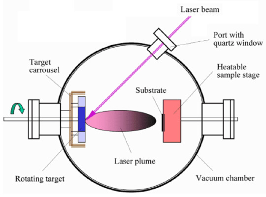
Pulse laser deposition is a physical deposition(PVD) method. In this method, the high-power pulsed laser beam focuses on the target that is inside the vacuum chamber. The target material is vaporized by a laser beam in the form of a Plasma Plume and deposit on the substrate as a thin film. This process can be performed in a high vacuum environment or in an environment with background gases such as oxygen. Oxygen is usually used for the oxide deposition to completely oxygenate the deposited thin film during the pulsed laser deposition (PLD) process.
While the equipment needed to perform the deposition in this manner is roughly similar to other deposition methods (such as sputtering), the physical interaction between the laser beam and the target material and the formation of the thin film is very complex. When the laser pulse is absorbed by the target, its energy is first converted to electron excitation and then thermally, chemically and mechanically, resulting in vaporization, ablation, plasma formation and exfoliation of the target material. The particles separated from the Target surface are distributed in a vacuum environment as a plume. These energetic particles include atoms, molecules, ions, electrons, and molten globules that will be deposited on the substrate.
https://lnkd.in/dR9qrAC
The precise mechanism of the PLD process is complex, including the process of target material ablation by laser irradiation, the creation of plasma plume with energetic ions, electrons, atoms, molecules, and the charge-free particles and process of the crystalline growth on the substrate. In general, the PLD process can be divided into four parts:
Laser absorption at the target material surface, its ablation, and plasma formation.
Plasma dynamic.
Deposition of the material separated from the target on the substrate.
Nucleation and growth of the thin film on the substrate surface.
Each of these steps will have a significant impact on the crystallinity, uniformity, and stoichiometry of the thin film.
The separation of atoms from the bulk of matter is accomplished by evaporation at the surface under unbalanced conditions. The laser pulse penetrates the surface of the target material to a specific penetration depth. Depth of penetration depends on laser wavelength and refractive index of target material at laser wavelength. For most materials, this depth is about 10 nm. The strong electric field created by the laser beam causes the electrons to be separated from the bulk. This process is performed in a pulse of 10 picoseconds or nanoseconds and occurs due to nonlinear processes such as multi-photon ionization. These nonlinear processes increase due to surface microscopic cracks, holes and nodes, and increase the electric field intensity. Free electrons oscillate in the electromagnetic field of the laser light and collide with the atoms of the bulk of matter and transfer energy to the atomic lattice of the target material’s surface. As a result, the surface temperature of the target material increases and vaporizes.
Secondly, due to the Colombian repulsion and recoil from the target material surface, the evaporated material expands into the substrate perpendicular to the target material surface. The spatial expansion of the created plasma plume depends on the vacuum chamber pressure. The dependence of the shape of the plasma plume on the pressure can be described in three stages:
The vacuum phase, where the plasma plume is very narrow and forward. Almost no scattering with background gases occurs.
The middle region where the separation of high-energy ions from low-energy species can be observed.
High pressure region where we find a more diffusion-like expansion of the ablated material. Naturally this scattering is also dependent on the mass of the background gas and can influence the stoichiometry of the deposited film.
The most important consequence of increasing background pressure is the slowing of energetic species in the expanding plasma plume. It has been shown that particles with kinetic energy of about 50 eV can re-sputter the film deposited on the substrate. This reduces the deposition rate and changes in the stoichiometry of the deposited thin film.
https://bit.ly/2Xhapfo
The third step of the PLD process is very important in determining the quality of the deposited thin film. High-energy particles are ejected from the target and bombard the substrate surface. This process can damage the substrate surface and sputter the atoms on the surface. It may also cause a defect in the deposited film. The particles scattered from the substrate and the particles emitted from the target material form a collision zone that acts as a source of particle condensation.
When the density is high enough, thermal equilibrium is created and the thin film grows on the substrate surface at the expense of the direct flow of ablation particles and the thermal equilibrium obtained. The process of nucleation and growth kinetics of the thin film depends on several growth parameters, including:
Laser Parameters Factors such as laser fluence (Joule/cm2), laser energy and degree of ionization of the material separated from the target surface are effective in film quality, stoichiometry, and rate of deposition.
Surface Temperature: Surface temperature has a great influence on the nucleation density. In general, the nucleation density decreases with increasing temperature. Surface warming can be caused by the use of a Co2 laser.
Substrate Surface: Nucleation and growth are affected by surface preparation. Surface roughness due to processes such as etching has an adverse effect on the process.
Background Pressure: Oxygen is usually used as background gas in the oxide deposition to ensure proper stoichiometry of the thin film. If the oxygen pressure in the chamber is low, the nucleation, stoichiometry and quality of the deposited thin film will be affected.
During the laser pulse in the pulsed laser deposition(PLD) process, the substrate surface is saturated. Depending on the laser features, the pulse takes about 10 to 40 microseconds. The saturation of the surface results in a higher density of nucleation in this method than in the sputtering method, which results in the smoothness of the deposited thin film.
The PLD method has significant advantages over other deposition methods such as:
The stoichiometric transferability of materials from Target to the substrate, the precise chemical composition of a complex material such as YBCO, can be reproduced in the deposited film.
Deposition rate is relatively high (usually 100 angstroms per minute). Also, the thickness of the deposited thin film can be controlled simultaneously with the deposition process only by turning the laser on and off.
The fact that a laser is used as an external energy source results in a very clean process without heat filaments.
Despite these important advantages, the industrial use of PLD is low and to date most applications have been limited to the research environment. There are basically three main reasons for this:
The plasma plume created from the material separated from the target surface by the laser beam is in the forward direction as a result the thickness of the particles accumulated on the substrate being non-uniform and the composition of the created thin film may change extend along it and away from the center of accumulation. The resulting film area will also be small (approximately 1 cm 2).
The created plasma plume also contains melt globules with an average diameter of 10 μm. Reaching these particles to the substrate will reduce the quality of the thin film.
The processes, which occur in the plasma produced by the laser, are not fully understood. As a result, new material deposition usually involves a period of experimental optimization of coating parameters.
Using the Target Manipulator’s laser point movement technique on the surface of the target material, or the substrate motion during the coating, the first two problems are largely solved and the PLD method can be applied to deposit films with a uniform thickness and composition.
The Vaccoat Co. PLD device is equipped with the Target Manipulator system. This pulsed laser deposition(PLD) system is capable of producing thin films of uniform composition and thickness in all substrate areas. It also has a vacuum thermal evaporation with three heat evaporation sources to perform thermal evaporation coating. For more information visit the site of Vaccoat Company.
https://lnkd.in/dR9qrAC
https://bit.ly/2Xhapfo
#nano#nanotechnology#nanomaterials#deposition#vacuum#vacuum deposition#laser#pulsed laser#pulsed laser deposition#pld#pvd#physical vapor deposition
0 notes
Text
Material Deposition Table to Select the Appropriate Method of Vacuum Deposition

Vacuum deposition technology is a wide range of different deposition methods(method of vacuum deposition) that are used to create single or multi thin film layers of several nanometers to several micrometers of different materials and compounds on different surfaces in a high vacuum system and have various applications in industry and research fields. In general, the process of deposition of the thin films in vacuum conditions consists of three main parameters: the target material, the substrate, and the process of transferring the material from the target to the substrate.
Due to the fact that different elements, alloys and compounds have different physical and chemical properties, choosing the appropriate and efficient deposition method is one of the key points in the vacuum deposition process. The properties of the deposited thin film depend on many parameters such as the temperature of the coating, the nature of the substrate, the composition of the residual gas in the vacuum chamber, the rate of the deposition, and etc., which should be reviewed and researched according to the desired application.
https://bit.ly/2CQcjMq
https://lnkd.in/dcHGnXf
Our Systems & Tables
In order to choose the best method for deposition of the different materials, it is necessary to have a set of information that, according to the characteristics of the material, expresses the efficiency of each method for its deposition. In other words, not every material can be deposited in any way. For this purpose, tables called material deposition tables have been provided to help users of vacuum deposition systems to select the best deposition method.
It is strongly recommended to ensure that the correct method is selected before attempting to deposition process, especially when you are going to deposit a new material. For this purpose, refer to the website of VacCoat Ltd. and our products.
See the material deposition table here:
https://bit.ly/3eFJMGx
Material Deposition Table | Guidance To Select the Appropriate Method of Vacuum Deposition
0 notes