
magicclam
Magic Clam's Old Things
Vintage electronics, restorations and things that gather dust.
310 posts
Last active 2 hours ago
Don't wanna be here? Send us removal request.
Last Seen Blogs

tvgerl
tina

thenondescript
Public Use Subject

2dpantyhosegirls
Animegirls*pantyhose

nuranibicarasblog
Nurani Bicara

Text
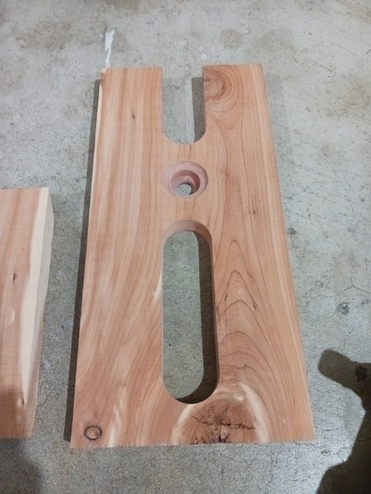

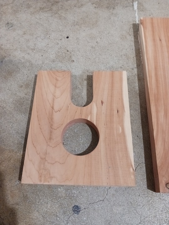
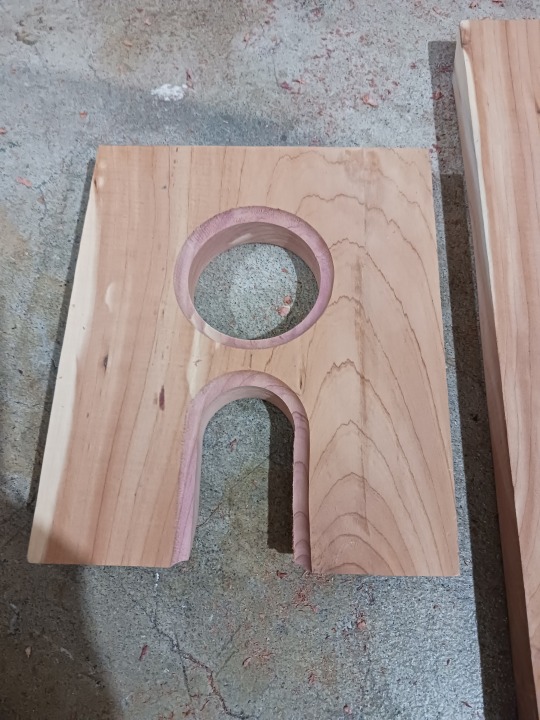

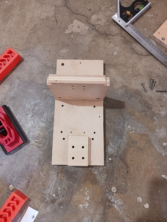
Wow... it's been a long time since I posted on here. Haven't had very much shop time over the past few months, but as the weather warms up I'm hoping to spend more time out there.
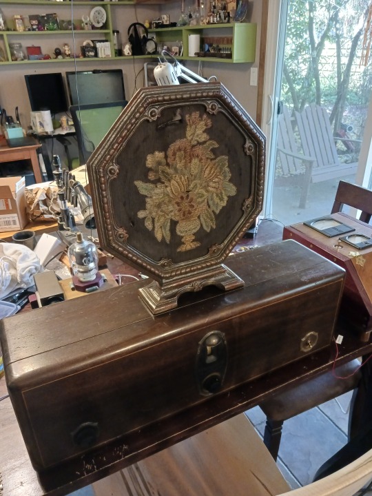
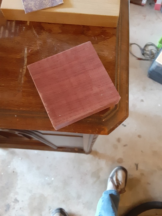
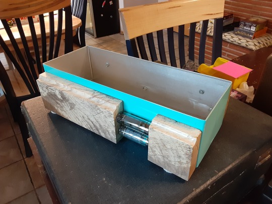
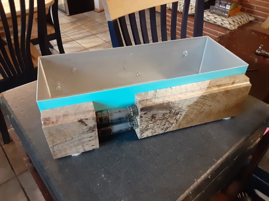
Quick update on the Heathkit A7e amplifier project. The pictures above are of the decorative enclosure for the power supply unit. The wood is cedar. I added a decorative recess to the cutout areas, then glued up the two boards. Next step is to fill some voids in the wood, then apply some finish.
Stay tuned for more posts (hopefully sooner than a few months!)
3 notes
·
View notes
Text
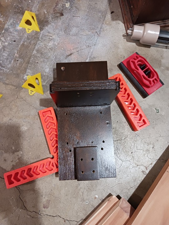

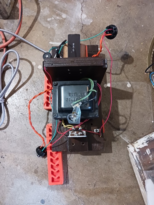


Progress on the Heathkit amplifier project!
This sequence shows the progress of the power supply unit I'm building to power both Heathkit amplifiers. Since the inside of the power supply is just plywood, I used a dark gel stain to unify the wood and make it look a little nicer. Then put on a few coats of satin poly.
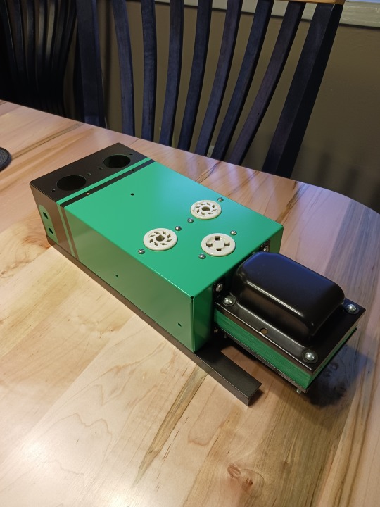
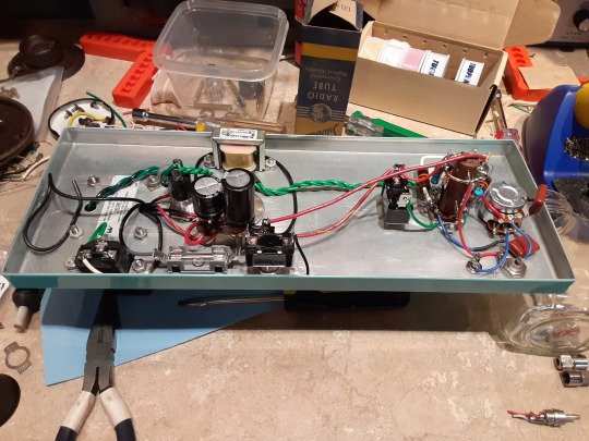
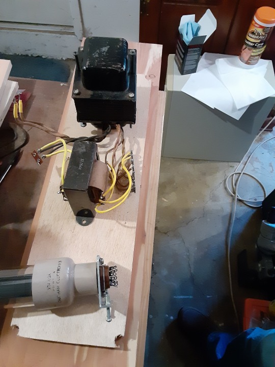
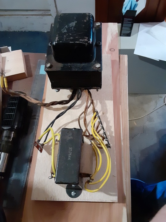
Next I added the internals. There's a power transformer which supplies 5 volts for the rectifier tube as well as B+ voltage for the plates, then there's a secondary filament transformer which provides 12.3 volts for the tubes in each amplifier.
Pictures 5 and 6 show the decorative cedar enclosure which will fit over the power supply. I'm particularly pleased with how the power light looks when lit!
Last picture shows one of the amplifiers plugged into the side of the PSU. The other amp will plug in on the other side.
I have a little issue right now where my B+ voltage is low under full load. It's supposed to be 390V, but I'm getting more like 360V. Right now debating whether to swap out the power transformer or just run it on lower voltage than the schematic calls for.
Will keep you posted, stay tuned!
21 notes
·
View notes
Text


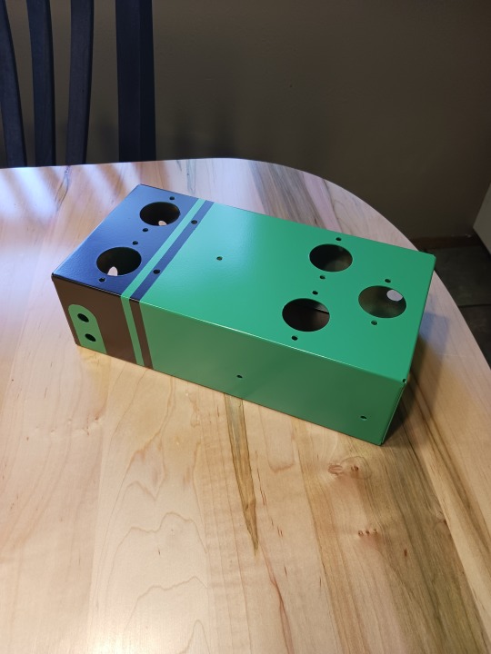
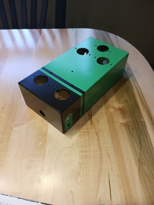
Man, it's been forever since I posted on here. Life has been busy and the weather has been hot, so I wasn't able to be in my shop much. However, I've had some time recently, so here's a project I'm working on...
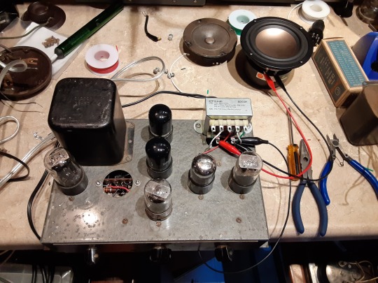
Years ago I got these Heathkit amplifiers at an antique radio sale. They've never worked, even after re-capping. Many years ago, I thought that one of the power transformers was bad. In my under-educated haste, I got rid of it.
In retrospect, I think it was probably fine. It turned out that both output transformers were bad. So now I was left with 2 amplifiers, but only 1 power transformer. I decided to design a power supply to power both amps and mount them both on a central chassis. These first pics show what the amplifiers used to look like, then after a re-paint.
Next step is to put them back together, and finish the electrical work on the amps and the power supply.
Stay tuned for more!
30 notes
·
View notes
Photo


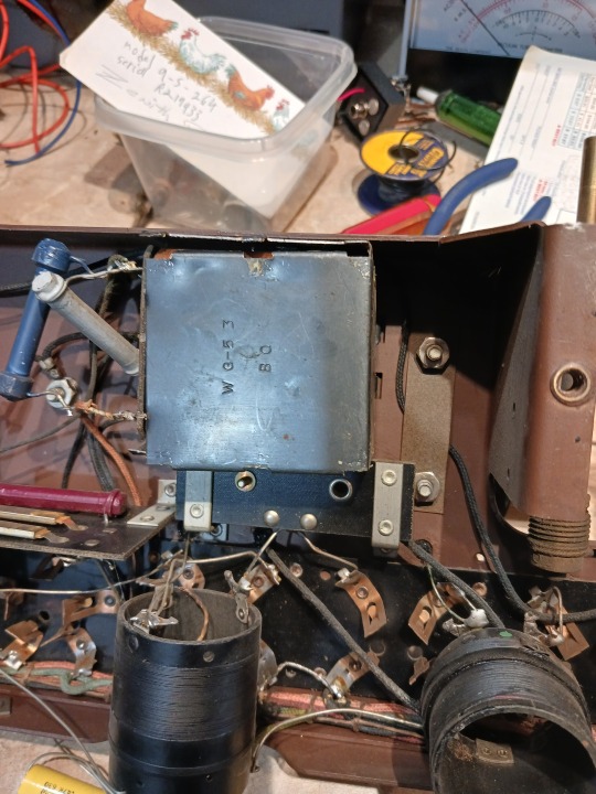

Realized that I never posted the RF section restoration of my Radiola 18. This is the second post on the 1-day restoration I did months ago. I started out by repairing the wirewound rheostat that acts as the volume control for the radio.
There was a small break in the resistive wire a little more than half-way along the travel of the volume control. I put a small blob of solder there to re-connect the wire and restore continuity. The small change in the resistance this repair causes really doesn’t matter in this application.
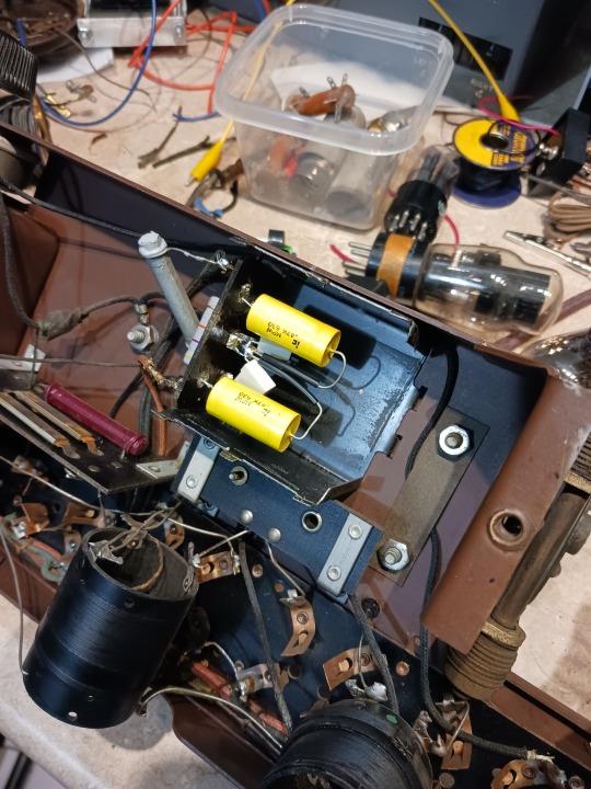
Next I replaced the capacitors which were mounted in a small metal box under the chassis. I took the box apart and pulled the large old caps out. Soldered in some new ones, then re-secured the box.
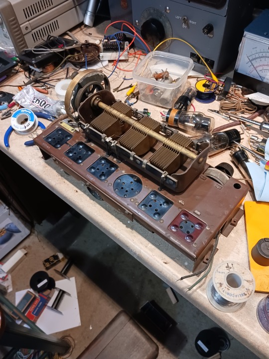
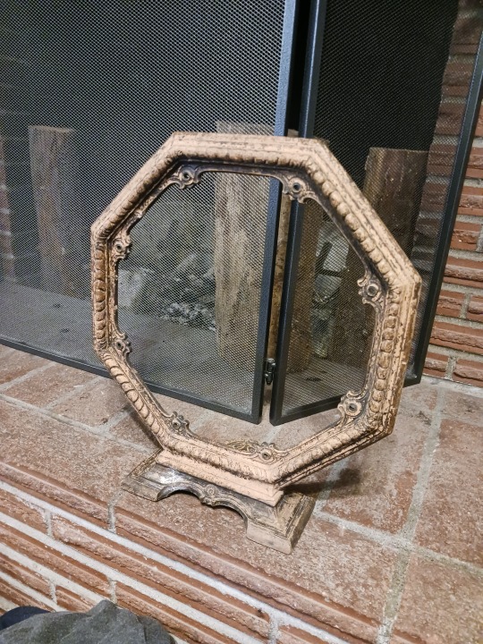
Next I cleaned up the chassis which was in really good shape. Last step was to freshen up the speaker that came with it. I wasn’t able to do anything with the grill cloth which has some wear and tear in it. But I was able to restore the frame which had mostly chipped and faded to the point where the original color was gone.
Last pic shows the finished radio. It plays quite well and I’m very happy with this project.
Stay tuned for some other kindof thing!
31 notes
·
View notes
Photo


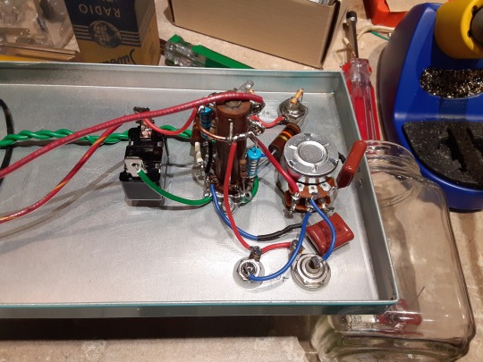
Here’s the audio section build for my preamp.
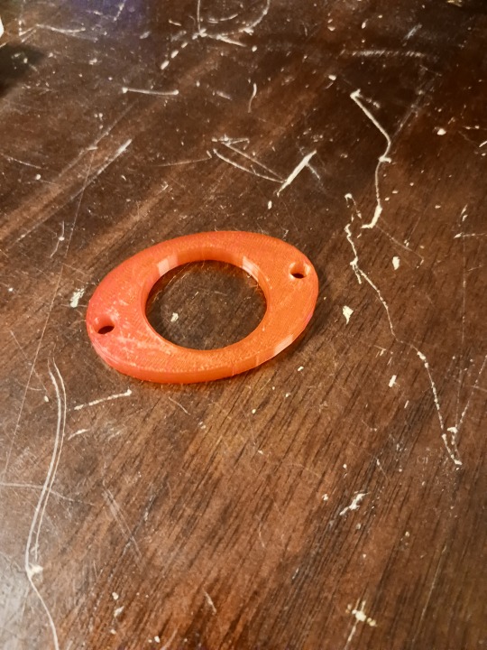
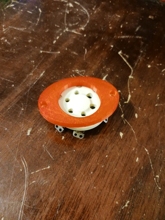
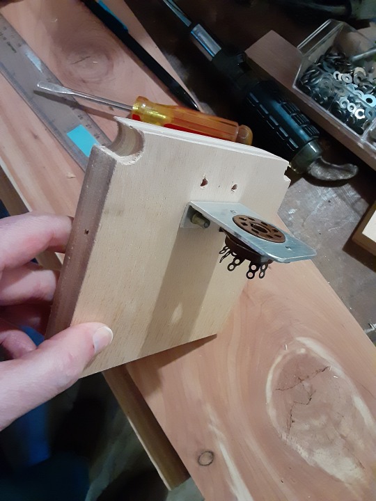
The first few pictures show a custom spacer that I 3D printed for the audio tube sockets. These sockets mount below the chassis, but there are small metal studs on top which could short to the chassis. So I took some measurements and used my 3D printer to create some spacers to stabilize and isolate the sockets.
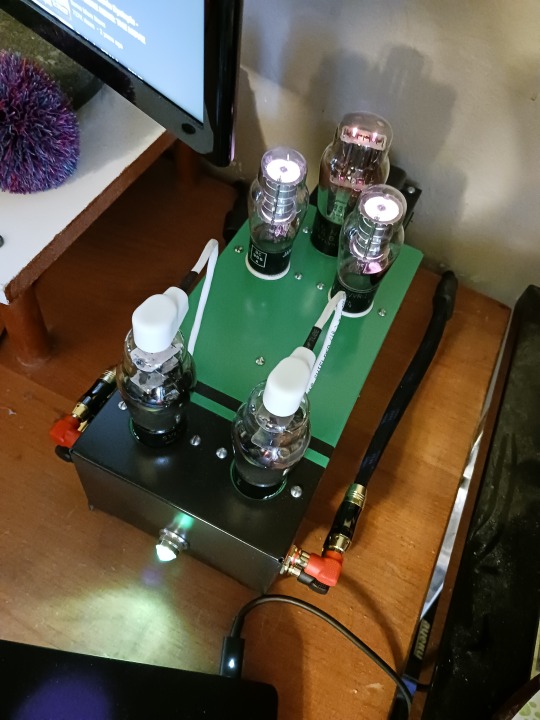
For this preamp, the inputs are connected to the grid caps of the Type 75 tubes. You can see the wires attached to the top of the tubes in the last pic. Then the signal is picked up off the plates and fed to the outputs through some .47uF capacitors.
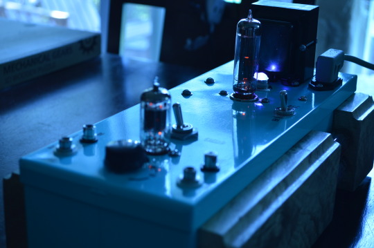
Last picture shows the finished preamp! You can see the regulator tubes glowing in the back. I’m really happy with how this turned out. It sounds excellent and was a really fun build.
Stay tuned for whatever’s next!
8 notes
·
View notes
Photo
Hey everyone!
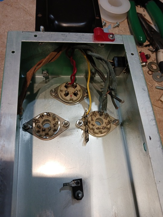
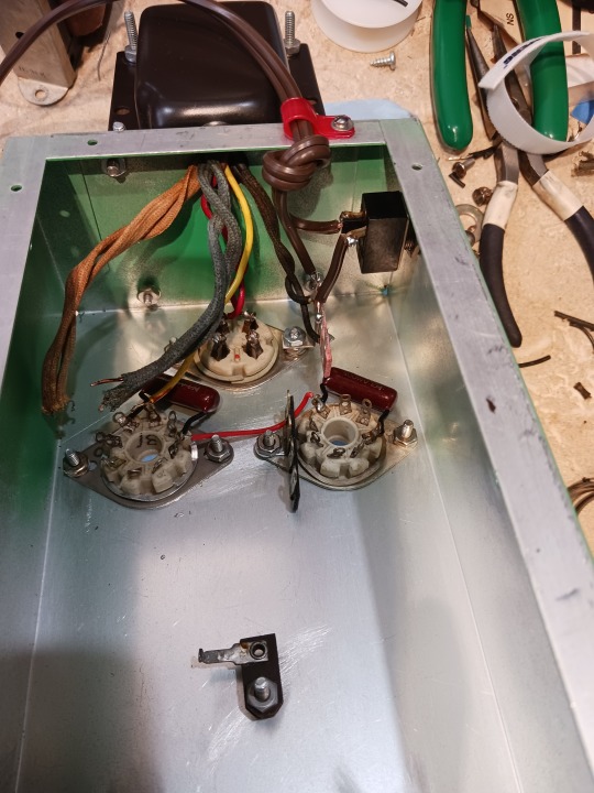
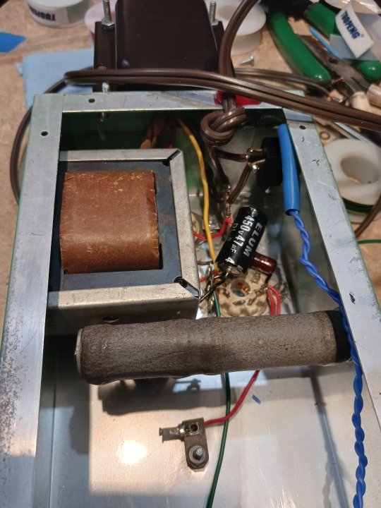
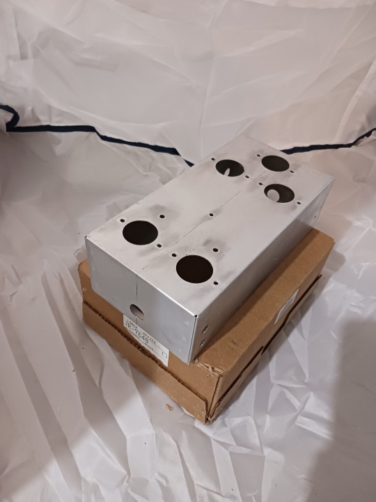
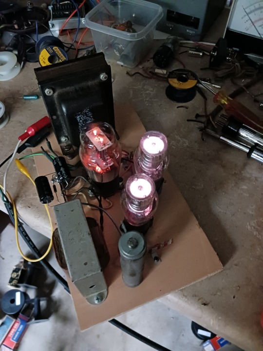
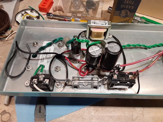
Here are a few photos of the power supply section assembly process. My goal here was to use parts I had on hand, most of which are vintage, and therefor... large.
First 2 pics show the rectifier tube socket (4-pin) and the regulator tube sockets. I soldered in some .05uf capacitors across the regulator tubes to prevent any noise from getting to other parts of the circuit.
Next I added the filter choke (square grey and brown thing in the last pic) and a large dropping resistor which lowers the incoming high voltage to the correct level to drive the regulator tubes.
I then pick up the B+ (high voltage) from the regulator tubes and feed it via the red wire you can see going to the solder tag at the bottom of the last pic to the plates of the audio tubes.
You can also see the twisted blue wires along the right-hand side of the last picture. These are the filament wires that power the pilot lamp as well as the audio output tubes.
Stay tuned for the audio section assembly!
17 notes
·
View notes
Photo


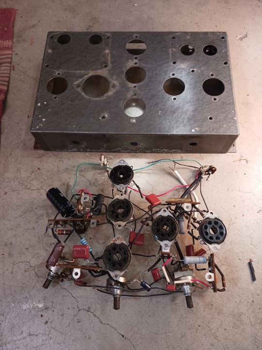
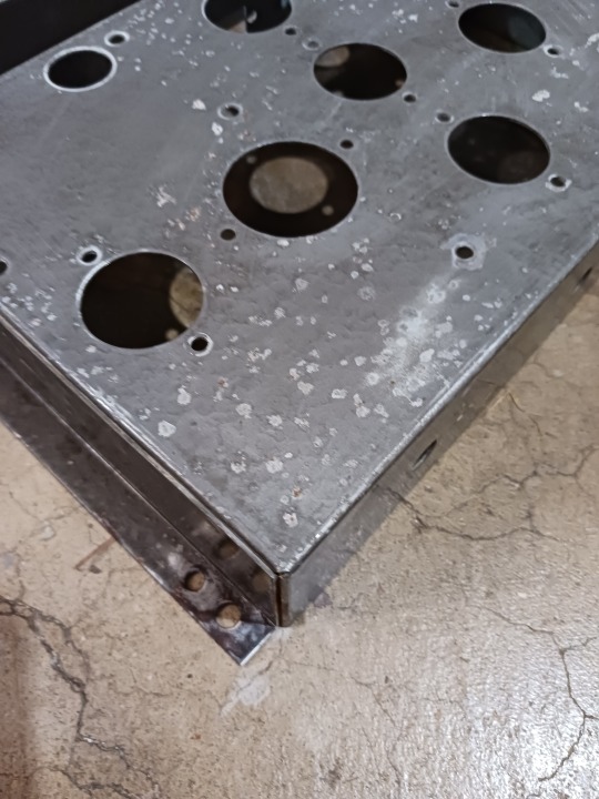
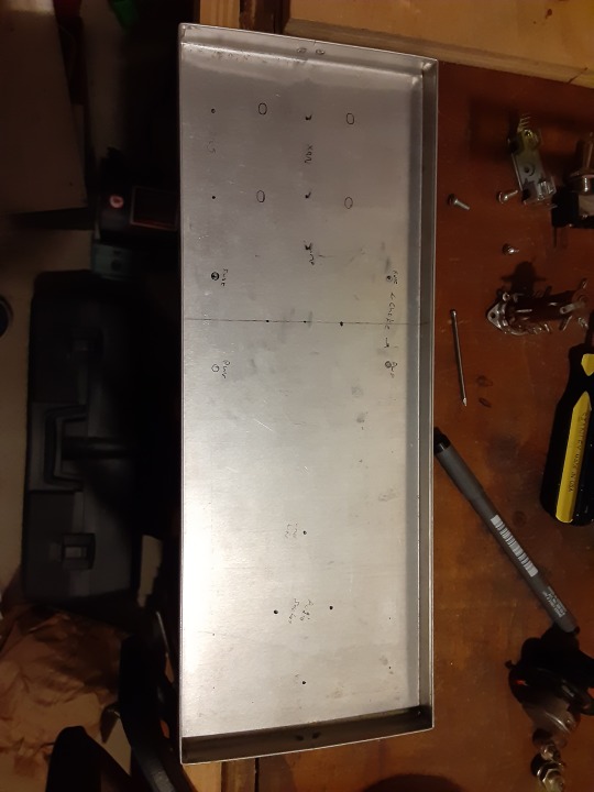
Here’s the partial chassis assembly for my vacuum tube preamp!
Really happy with how this came out. I drilled many many holes, and most of them were even in the right place!
After the holes were drilled, I primed and painted the chassis. This ended up taking a long time because the paint I used couldn’t be top-coated for 48hrs after application. Plus I had some business travel that happened during January, so it ended up taking more than 3 weeks start-to-finish.
As you can see in the last pic, I didn’t have space on top of the chassis to mount the power transformer. So I mounted it to the back. This meant I needed to create some stabilizing legs so that the whole chassis didn’t tip backwards with the weight of the transformer. You can see those in the last 2 pics.
Stay tuned for the final assembly!
15 notes
·
View notes
Photo


A while ago, I challenged myself to do a 1-day restoration of one of my radios. Start-to-finish.
I chose a Radiola 18 that I’d gotten back in summer. Started with the power supply section (as usual). It may look gross with the tar everywhere, but it’s electrically sound.
I replaced the few capacitors that needed replacing, and eventually added a fuse as well. The capacitors were all located in a square can on top of the chassis, but rather than dig out all the tar and old caps that were in there, I just disconnected them and mounted new ones underneath.
Finding room under the low chassis was a bit of a challenge, but worked out just fine.
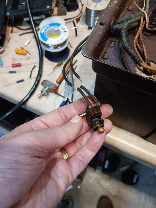
Initially I thought the power switch was bad, but it turned out to be ok, so I reattached it later.
Next step is the RF/Audio section, so stay tuned for that!
33 notes
·
View notes
Photo

Sometimes you partially restore something, then completely forget about it...
Or maybe that’s just me. :)
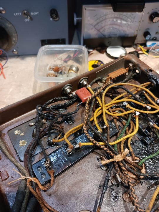
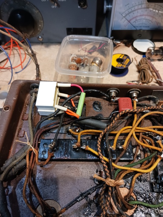
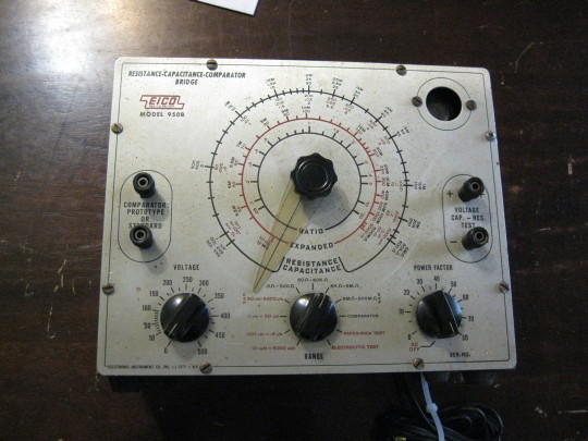
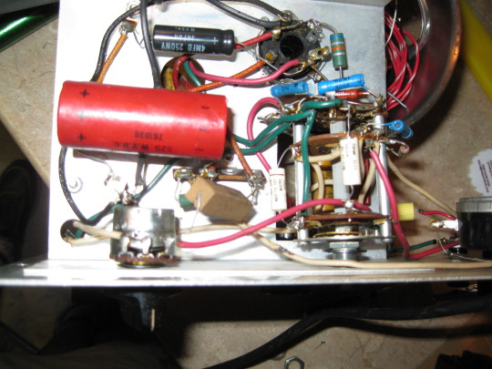
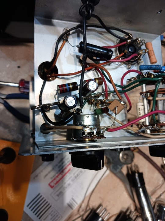
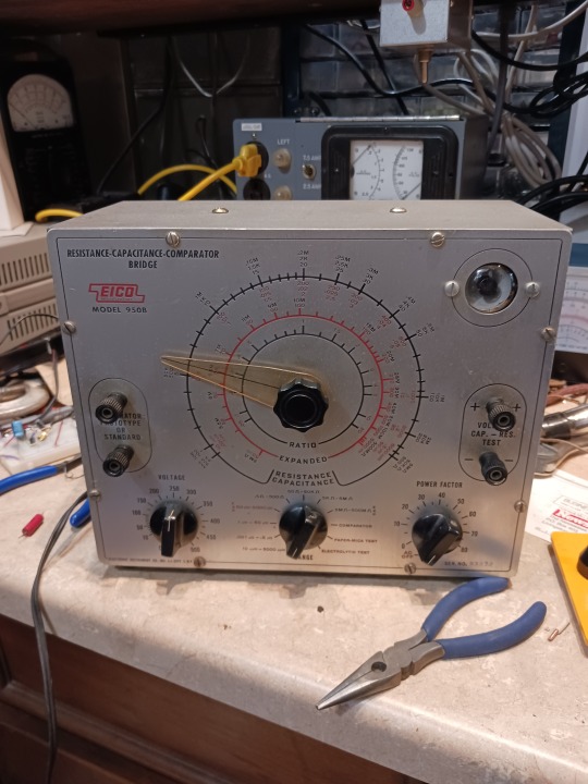
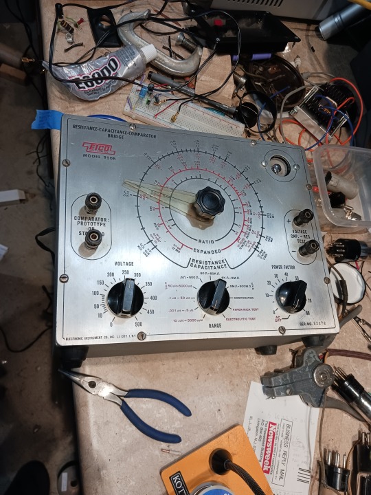
I recently got a new ‘like’ on an old post about this Eico 950b capacitor checker. I’d purchased it as part of a pair of Eico devices (the other was the RF generator I restored) from a flea market back in the ancient days.
I scrolled through the photos of the restoration, but I didn’t remember working on it or where it had ended up in my shop. This prompted an investigation. Turns out it had landed in my Cabinet of Mystery, which is a cupboard under my workbench where pieces of old technology just seem to appear from nowhere.
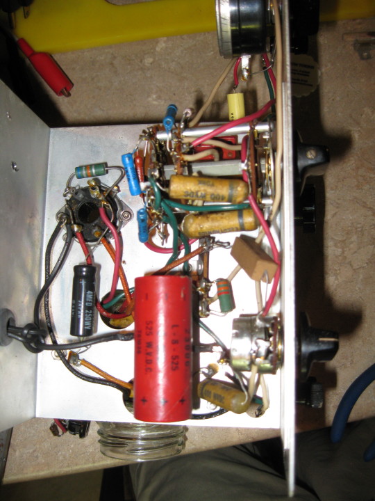
According to the old post, I’d replaced all of the old paper caps, but had stopped because I didn’t have an appropriate electrolytic capacitor (big red cylinder in the 3rd and 4th pics). The electrolytic is 8 microfarad at 525V. I found a 10 microfarad online, but it’s only 500 volts, and the schematic says there’s 520 volts across the cap.
So I did some research and decided to throw a few capacitors in series to create a ‘single’ capacitor of around 8mf at 550 volts. Found the right caps in my drawers of parts, but in my reading it was suggested that to make sure each capacitor charges evenly, you add resistors in parallel with each cap.
This basically acts like a voltage divider and helps ensure that the capacitors are both charged similarly. So I replaced a single component with 2 capacitors and 3 resistors. Not exactly making things simpler...
I cleaned up the faceplate, plugged it in, did a quick calibration and it seems to be working great! I’ve put it on my bench now, and look forward to using it whenever I need to check capacitors.
Stay tuned for something else!
17 notes
·
View notes
Photo


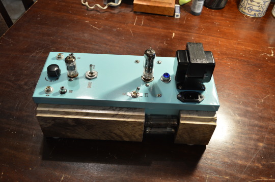
Put the finishing touches on my vacuum tube power supply yesterday.
This is the first time I’ve designed any tube gear from scratch, so I was really relieved when it didn’t blow up. :D
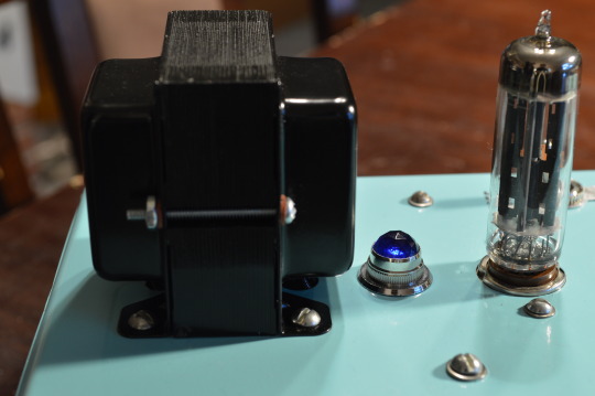
This supply uses a type 83V rectifier and 2 0D3 voltage regulator tubes, outputting around 300V at 40mA. I’m going to use this supply to power a vacuum tube preamp. I know I’ve built one of those already, but the one I built is a line-level preamp. I’d like to build a phono preamp so I can experiment with a pure analog signal from my turntable, through the preamp, into my vacuum tube amplifier and out to my speakers.
The 0D3 tubes aren’t really necessary for this application, but I wanted to use them because they glow a cool purple-pink color when activated. Like other builds I’ve done it’s part function, part aesthetics.
Next step is to order some of the parts (mostly electrolytic capacitors) I need for the audio section, then layout a chassis and start building!
Stay tuned for other things that glow.
38 notes
·
View notes
Photo

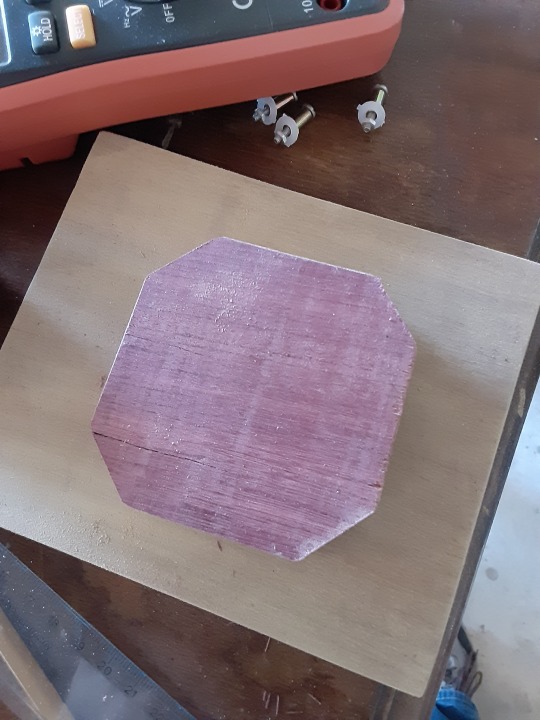

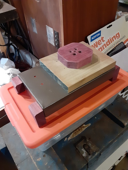

Had some time recently to put the finishing touches on my battery-powered AM transmitter.
I started this project because the AC-powered AM transmitter I have picks up a lot of noise from the electronics in my house. I figured I’d have a better chance of noise-free listening if I was using a battery-powered transmitter.
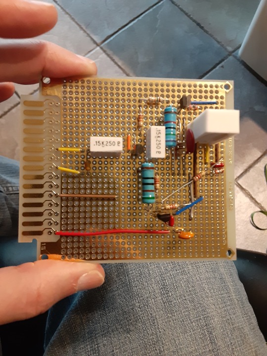
I found a YouTube video from Gregg’s Vintage Workshop where he built this transmitter in the point-to-point wiring style on a cutting board. I used his drawing (schematic) and modified it to fit onto a small perf-board. Then I built an enclosure for it.
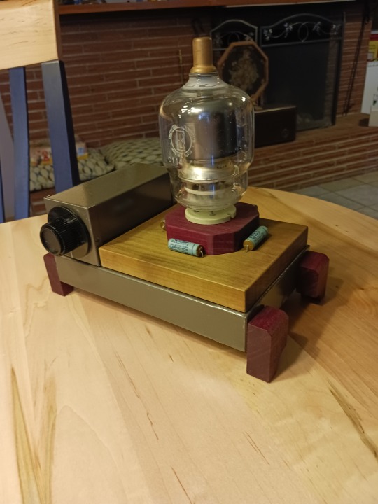
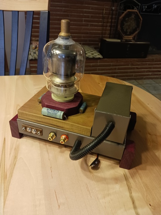
The enclosure is an old metal chassis I had. I primed and painted it in a hammered metal finish. Then I grabbed some scraps of wood (purple heart and poplar) to add some nice decoration to the metal. Lastly I added an old dead vacuum tube to the top as a finishing touch. Finished the wood with boiled linseed oil which really brings out the color.
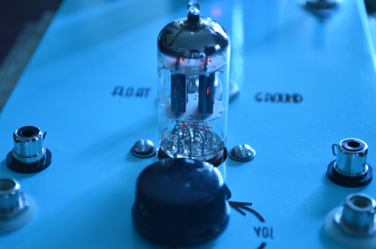
At first I had some grounding issues with the enclosure, since it’s battery-powered, it needed a floating ground instead of grounding to the chassis.
Once I isolated the RCA jacks and tuning capacitor, it sprang back to life.
The other night I got it working with my Bosworth antique radio. Was pretty fun to tune into my own radio station and hear Spotify in low fidelity. :D
Stay tuned for more fun with electronics!
62 notes
·
View notes
Photo
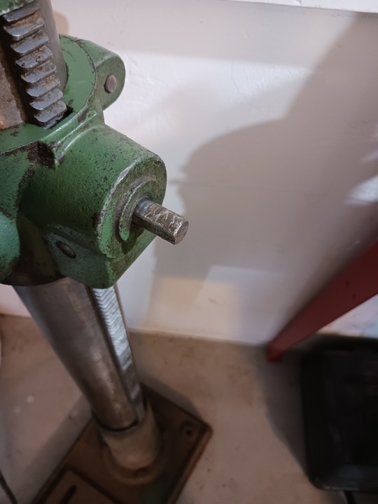


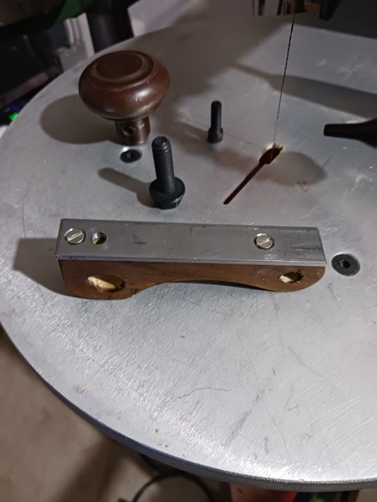
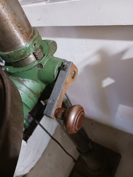
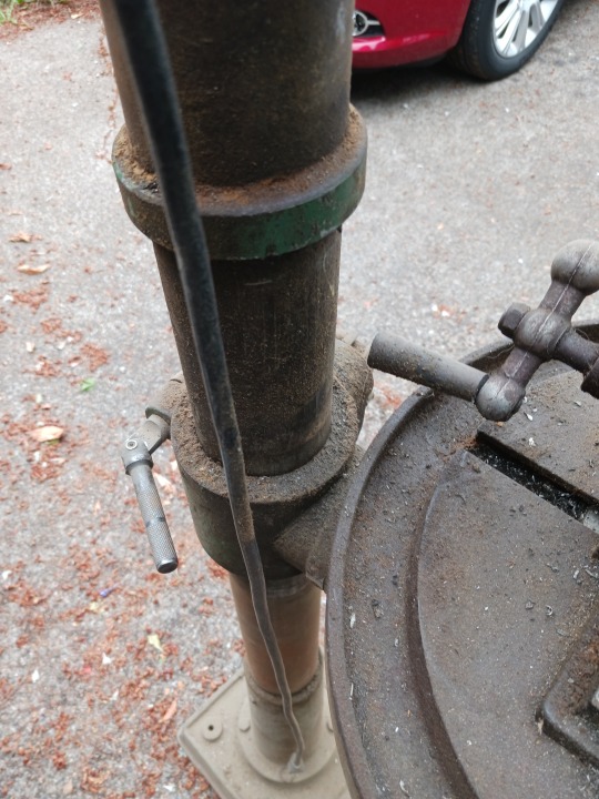
When I got this drill press, it didn’t come with a handle... or rather... it had a pair of vice grips clamped on to the spindle where a handle should be.
Not wanting the vice grips to be a permanent solution, I decided to build a handle for it.
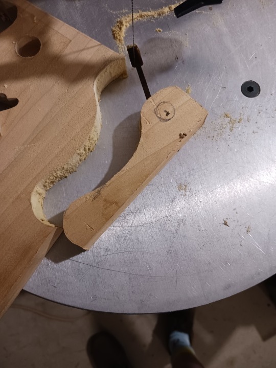
First I needed to scrounge some parts. Got a piece of poplar, some 1/8in thick steel, some screws and an antique doorknob.
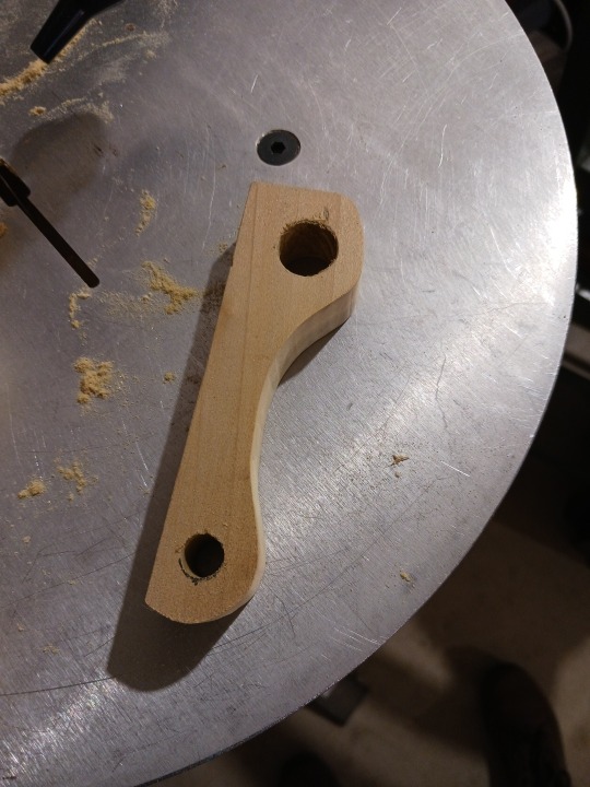
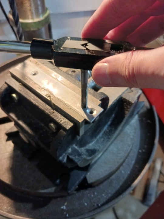
I cut a handle shape out on my scroll saw, then drilled holes in the poplar. Next I cut the steel to length and drilled some holes in it as well. 2 holes to screw into the poplar, and 1 hole which I tapped for a threaded set screw. This set screw allows me to attach the handle to the drill press.
Lastly I assembled the whole thing, using a bolt screwed into the doorknob so that it rotates freely. I also stained the poplar to a darker brown so it more closely matched the doorknob color. :)
Overall, I think this turned out pretty great. It matches the rugged aesthetic of the rest of the drill press. At some point I may put a metal sleeve in the hole where the doorknob goes to preserve the wood, but for now it’s functional and I no longer need the vice grips.
It’s been WAY too hot here for the past week to do anything in my shop, so hopefully it’ll cool down soon and I can get back out there.
Stay tuned for more random builds!
10 notes
·
View notes
Photo
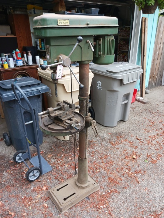


Last weekend a friend of mine reached out to let me know that her uncle and father (who were contractors during their careers) were having a tool sale.
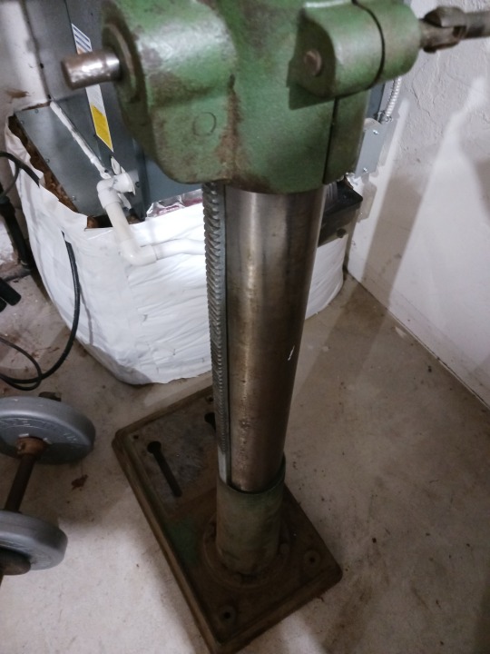
One of the things they were selling was a floorstanding drill press. I’ve wanted one for a long time, and this was a good opportunity to get one at a reasonable price. It was supposedly working when I got it, but that was really only true at a basic level.
When I plugged it in, the drill chuck spun.
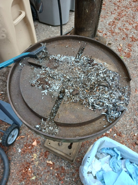
However... the platter was gunked up and rusted so it wouldn’t move. I removed the cross-slide vice from the platter (2nd and 3rd pics) to find a pile of sawdust and chips underneath. After 6 rounds with degreaser, I got the platter clean.
Then spent a bunch of hours on Sunday scrubbing the metal parts with WD40 and steel wool to clean them up and de-rust. Pic 6 and 7 show the motor mount slide which was so rusted it wouldn’t move either. Last few pics show the main column before and after. Managed to get most of the rust off it, so it works well now.
Still more cleaning and work to do on it.
Stay tuned for more projects!
8 notes
·
View notes
Photo


Here are the final glamor shots!
As a finishing touch to this build, I reached out to my mom who has a Cricut machine to see if she’d be willing to cut some vinyl letters to label the switches and RCA jacks on the preamp.
She was happy to help, and when my folks came by last weekend, she brought the cutout letters with her and showed me how to apply them. I think it turned out awesome! Now I don’t have to remember which are the inputs and which are the outputs etc. :)
I also have a friend with a nice camera (https://squeebirdstudios.tumblr.com/) who was willing to come over and take some final shots of the project. Above are some of the ones I really liked.
Very happy with this one, and looking forward to more from-scratch builds.
Stay tuned for another Zenith restoration!
29 notes
·
View notes
Photo


It’s finished!
So yesterday, the stereo volume control I’d ordered arrived. This was the last piece preventing me from finishing my vacuum tube preamp project. I’d initially ordered the wrong part (mono volume control), so I had to order the correct thing.
First few pics show the base construction. I’d had this cool wood with a super crazy grain for a long time, so I decided to use it to decorate the sides of the aluminum box. Then I thought it’d be neat to add some dead vacuum tubes on the sides as accent pieces. Overall, really happy with the aesthetic.
Next pictures show the wiring process. The keen-eyed among you might notice that I swapped out the switch in the audio section, and you can see the different potentiometer as well. The switch was changed to simplify the design, though the original one would have worked too.
Pictures 8 and 9 are close-up shots of the power supply and audio output sections. I tried to keep them as separate as possible to avoid any noise from the power supply interfering with the performance of the preamp.
I’d powered the unit up slowly several times during the build process to make sure nothing would explode. Last picture shows the preamp hooked up with my HP audio generator as the signal input. It was feeding a sine wave into the Left and Right channel of the inputs. I’ve got my scope on the outputs and you can see 2 clean sine waves on the scope screen! This meant that the preamp was working properly!
This is the first time I’ve successfully built something from just a schematic, so I’m really proud of this one. Now I just need to figure out where I’m going to use it. :D
You can check out this, and many other designs on DIY Audio... link to this preamp designed by Matt Renaud below...
https://diyaudioprojects.com/Tubes/Universal-Tube-Preamplifier/
Stay tuned for more fun with electronics!
12 notes
·
View notes
Photo


Hey everyone, it’s been a while.
For a long time now I’ve had a vacuum tube preamp bookmarked from DIY Audio.
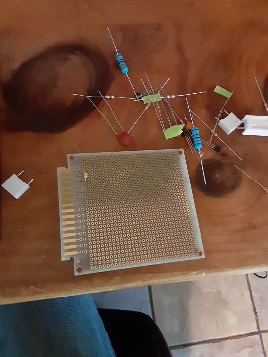
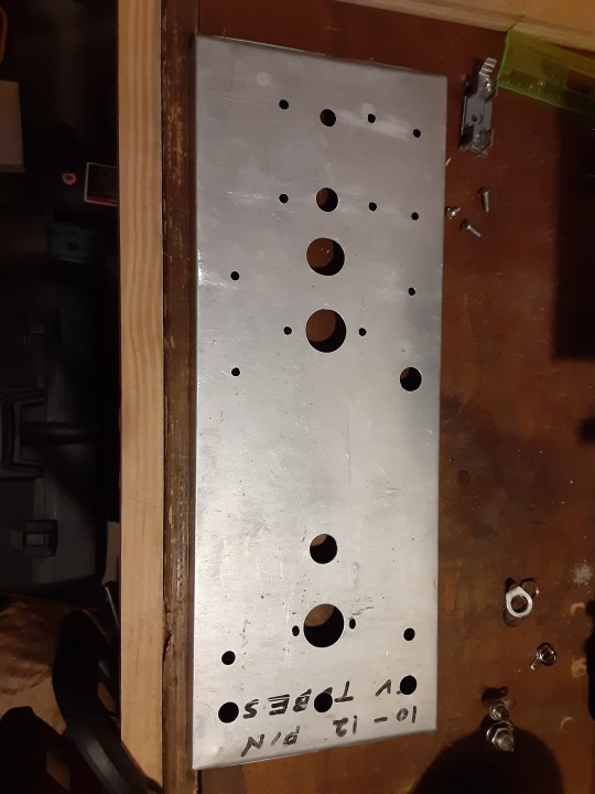
A few weeks ago, I finally had all the parts on hand to start the project. The pictures above show the process of laying out and assembling the chassis.
I had an aluminum box on hand that used to store vacuum tubes. Since I’d moved the tubes elsewhere, I figured it would make a great chassis for this preamp.
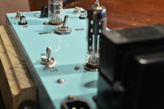
I started by marking out where the various components needed to go, then drilled the holes. I sanded them to smooth out rough edges, then test-fitted the parts to make sure I’d drilled everything correctly. Next I primed and painted the chassis. I chose teal because it looks nice and I haven’t seen many amps painted in cool colors. :D
Last pic shows the chassis assembled. I have a few modifications I need to make, including isolating the input/output RCA jacks (bottom of the last pic) from the metal chassis. I need to pick up some plastic washers to accomplish this.
Once all the assembly is done, I’ll do the soldering.
More to come... stay tuned!
8 notes
·
View notes
Photo

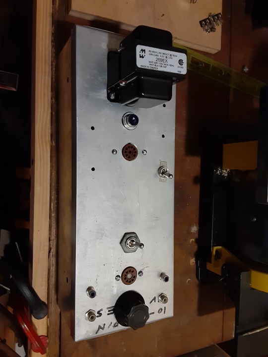
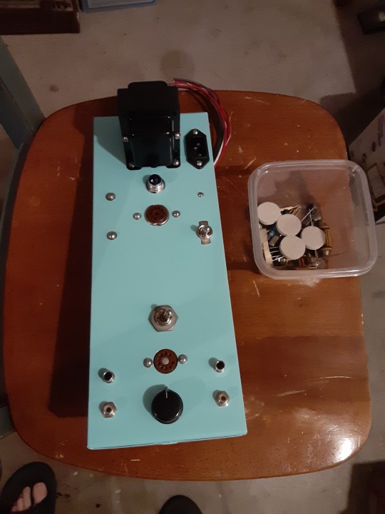
Been meaning to post this for a while now.
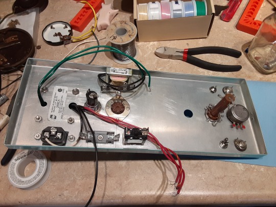
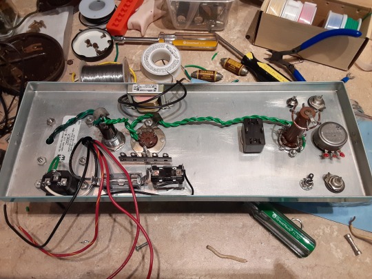
When it hasn’t been too cold to be out in my shop, I’ve been working on the Heathkit A7 amplifier project. These pictures show the central power supply unit that I’m building to power both amplifiers.
As I’d mentioned in a previous post, I’d stupidly gotten rid of the power transformer from one of the amps many years ago. Since the amps will be paired together, I thought it wouldn’t look very good having the original transformer on one and not the other.
So I’m building a power supply that will provide filament voltage and rectified DC voltage to both amps. Last picture shows the general build as it was a few weeks ago. I haven’t made much progress since, due to weather and general life stuff, but I’m hoping that I can get back to it soon.
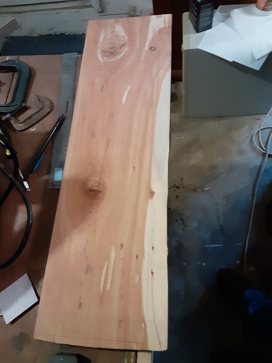
The cedar board you see in the second picture will be the cover for the power supply. Should look really nice when its done!
Stay tuned for more things that I’m not sure will work!
#Heathkit#tubes#vacuum tubes#amplifier#restore#modification#electronics#power supply#soldering#woodworking#fun
33 notes
·
View notes