
vovworks
Works Of The Voice of Vesper
A collection of works by Voice of Vesper
155 posts
Don't wanna be here? Send us removal request.
Last Seen Blogs
sallyawayfromhome
Sallyawayfromhome

sostanzaimperfetta
Entangled.

hometoursandotherstuff
Home Tours & Other Stuff
atripoz
atripoz

getfitfirstblog
GetFitFirst
Text
Favorite DBZ/S Movie
I can't fit them all in a poll, but I'm curious, what do you think is the best DBZ/DBS movie?
I listed them under the cut for reference
Dead Zone
The World's Strongest
The Tree of Might
Lord Slug
Cooler's Revenge
The Return of Cooler
Super Android 13!
Broly - The Legendary Super Saiyan
Bojack Unbound
Broly - Second Coming
Bio-Broly
Fusion Reborn
Wrath of the Dragon
Battle of Gods
Resurrection 'F'
DBS: Broly
DBS: Super Hero
4 notes
·
View notes
Text
I want to get together a group of queer folk to fuck around in Team Fortress 2 with
0 notes
Text
I built Conway's Game of Life in Blender just to see if I could >:3

I definitely didn't make it very efficient, but it WORKS!!
1 note
·
View note
Text

I wanted to test "animating" baked lighting, so I fully lit this house, baked the lighting to a 256x256 image, multiplied it by animated noise so that it would dim at random, and then fed it through a gradient to give it that burning look
Also messed with parallax texturing for the window reflection
My recreation of PS1's limitations really show with this one, I'm so glad!
1 note
·
View note
Text


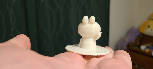
This was simultaneously the last art I did for 2023 and the first art I did for 2024! I modeled and 3D printed Kyorosuke as a Christmas gift for my friend @deathgloss on New Year's Eve and then I plopped into Blender to add materials and render a lil animation on New Year's Day!
Had to wait to post it because I wasn't seeing them until today :3
4 notes
·
View notes
Photo

Dream Weapon
I had a dream that I had a power that I could see weapons floating around and grabbing one would make it real
This was one of them
You hold it by the middle swirly part and it can face either way, both ends having different functions When holding the thin end out it's best for single target attacks and stabbing The wide end is meant for slashing at wide groups It's big enough that when holding it the end almost touches your upper arm It is entirely impractical in real life, but it looks cool
1 note
·
View note
Video
I was inspired to recreate an animation by isatorus with my own character, Silly! Their animation can be found right here!
5 notes
·
View notes
Photo

Video Call
This is part of a biweekly comic strip I've been making for work, this is the latest, just a real quick one about video calls
0 notes
Photo

Mawie's Birthday
I made this fanart of Mawie from Something Soup back on the 19th because it was the birthday for the voice actress! Just forgot to post it anywhere other than the Discord :p
1 note
·
View note
Text
As part of my art trade with my friend Dan I made this model of their character Mako! They're @SummonCircle on Twitter :3
2 notes
·
View notes
Video
youtube
I made an improved version of the PS1 wiggle effect! Now it works in real time!!!
8 notes
·
View notes
Photo

It’s such a simple design, but I’ve always been drawn to the Premier Ball
40 notes
·
View notes
Photo

I’ve been workin on this 3D model of my gal Silly!!!!
The weight painting needs some adjustments, but she lives!!! My gal is ALIVE!!! I used that PS1 wiggle effect from the tutorial I made too :3
20 notes
·
View notes
Video
youtube
I made a tutorial for creating a pixel perfect vertex snapping in Blender to mimic that PS1 style!
Full written version of the tutorial under the cut!
I'd like to give a huge thanks to Chris Prenn for their Blender Geometry Nodes Fields Frustrum Culling Tutorial which really helped me figure out a starting point for this method, a lot of what I do here is based on his tutorial with added and modified steps.
To start we need 5 input values
The camera we're using
The output X resolution
The output Y resolution
Don't set these too high or your computer WILL hate you!
The Focal Length
The Camera Clip End OR distance to apply the effect
We need to make a grid for your pixels, let's get it to the right size first
Add a Mesh Privative -> Grid to your Geometry Nodes setup
To get the aspect ratio of your scene let's take 2 math nodes set to divide
For the Size X we want to divide our X Resolution input from earlier by our Y Resolution input
Clamp that! This makes sure that it'll work no matter if it's a landscape or portrait style render
This actually makes the size exactly fit the edges of the camera, but we want the vertices to line up with the pixels of the camera, so we need to scale them ever so slightly
To do this we need to subtract 1 from the X Resolution and then divide that BY the X Resolution, then multiply that value with the prior divide step
For the Size Y use the inverse, just swap the X Resolution and Y Resolution inputs
For the Vertices X and Vertices Y values we're going to directly plug in the X Resolution and Y Resolution inputs, and now our grid is the right size! But we have to get it in the right PLACE as well!
Add a Transform node and plug in our grid
For the Translation value plug in the Location from the Camera input
For the Rotation value plug in the Rotation from the Camera input
Now our grid is sitting right on top of the camera, but it needs to be moved to the lens!
Add a Set Position node
Divide the Focal Length input by negative 32, this is the distance from the camera focal point to the lens
I'd like to note that I did have an issue in one project where 32 was not the correct value for the camera, I'm not sure what caused that, but if when viewing your grid it's not in the right spot try adjusting this number a bit, just make sure it sits right on the lens
Plug that into the Z of a Combine XYZ node
Add a Vector Rotate node and plug our Combine XYZ node into the Vector slot
Plug the Rotation from the Camera input into the Rotation value
Plug the Vector Rotate node into the Offset of our Set Position node, the reason we rotate it first is so that it moves the grid in the right direction instead of just along an axis, it will now always follow the selected camera, glued directly to the lens.
I tried doing this with a raycast node first, having the vertices of our model snap to the nearest spot that would hit one of the vertices of the grid, but I couldn't figure it out, so instead I used lines coming from the camera!
Add a Mesh Primitive -> Mesh Line
Set the count to 2 for optimum performance, we just need a start and an end point for our purposes
Leave the Start Location at 0
For the offset we're going to take our Camera Clip End, multiply it by -1, and plug it into the Z value of a Combine XYZ node
Add an Instance On Points node
Temporarily set your X and/or Y value to something like 16 while working on this part so your computer doesn't start crying
Plug the Grid into the Points and the Mesh Line into the Instance
For the Rotation value we're first going to subtract the Position from the Camera input's Location using a Vector math node, this gives a new vector pointing from the camera towards each line's starting point
We then plug that into an Align Euler to Vector node and set the axis to Z
Plug this final value into the Rotation and you should see your lines pointing directly out from the camera, if you go into camera view you won't see them at all because they'll be perfectly lined up
Now we're ALMOST ready to see results! Add a Realize Instances node and plug your Instance On Points node into it to make those lines REAL!
Plug your now realized instances into a Geometry Proximity node and set the type to Edges since that's what we got!
Add a Set Position node and plug your Geometry Proximity Position right into the Position input
If we plug our input geometry into the geometry field and take a look at the results, assuming you lowered the resolution earlier, you'll see a blocky looking mess, it's WORKING! However, you'll notice that if anything goes outside of the camera view it really doesn't look right, we have a fix for that using the raycast method from Chris's tutorial I mentioned earlier!
Add a Raycast node and set the Target Geometry to the Set Position node from before you instanced on points. Remember, this is the grid itself!
The Ray Direction will be the position subtracted from the camera location from earlier, that way the rays will fire towards the camera
For the Ray Length we'll actually want to plug that same node into a Vector Math Length node, that way we won't affect objects behind the camera, Chris explains why this works in the tutorial, but the basics is that's the length to the camera so it won't go Past the camera to hit the grid
Now plug the Is Hit from our Raycast node into the selection of the Set Position node, and voila! Your model will no longer freak out when it's outside the camera, it just won't be affected at all!
The very last step we should do is add a Switch node to swap between the original geometry and the wiggle-fied geometry depending on if it's in viewport or not, that's easy
Add a Switch node and set the type to Geometry
Plug the final Set Position node into the False field
Plug the Original geometry into the True field
Add an Is Viewport node and plug that into the Switch
You now have a functioning PS1 wiggle effect that is active in render! Here's a couple tips for using it:
Add a Triangulate Modifier before the wiggle Geometry Nodes for maximum accuracy
Set your Render type to Eevee and then under Film set the Filter Size to 0 to get hard edges in your render
If trying to show off that you have THE PS1 wiggle it's best to do subtle movements, slow moving models will have a more noticeable Pop
Make sure the geometry nodes for the wiggle are at the very bottom of the modifier stack below anything that may distort the model such as an armature or displacement texture
If your geometry nodes disappear from your editor make sure you have the Geometry Nodes modifier selected in the modifier stack
Back in the Render Properties tab under Color Management set your View Transform to Standard and the Look to None for accurate colors in your final render
Be sure to check if you have any compositing nodes set up in your default Blender file that they aren’t going to mess up your non-photorealistic style!
Have fun!
23 notes
·
View notes
Photo

Made a new DnD character last night! Her name is Killer and she's a wild magic barbarian winged tiefling!
4 notes
·
View notes
Photo

Still trying to get myself to make art more often even if it’s just a really quick doodle like this, just lil sketchy things so that I make something
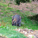
This fucking blanket looked like there was a creature sitting underneath it and it freaked me the hell out.
2 notes
·
View notes
Photo

I spent a huge chunk of today mapping out the continuities and relationships of every character I have with art...
The drow in the bottom right of the Aria bubble was drawn by my buddy @triplecolor a long time ago! I just...never drew my own character lol
1 note
·
View note