#diyelectronics
Text

PCB of the day! Metro ESP32-S3 🔧🔋💡
#adafruit#electronics#pcb#opensource#opensourcehardware#pcboftheday#metroesp32s3#techinnovation#circuitboard#engineeringlife#microcontroller#hardwaretech#diyelectronics#makerspace#electronicsdesign#manufacturing#nyc#technology
52 notes
·
View notes
Text
DIY Dumble-like sounding MOSFET Overdrive

The Hermida Zendrive guitar pedal we will study, assemble and listen to today is a true masterpiece. Many say its sound is close to the Holy Grail of guitar amplification - Dumble Overdrive Special.
Other people are more pessimistic in their judgments. Still, the precise response to the picking dynamics, the Voicing tuning options, and the sheer beauty of this overdrive's sound are simply impossible not to love.
But before we study the Lovepedal Zendrive or its copy of the Landtone Phoenix song, or the Aion effects Azimuth dynamic overdrive, we'll study the evolution of the MOSFET overdrives that finally resulted in the development of this gem.
Fulltone OCD

Mike Fuller was one of the first to start using MOSFETs instead of diodes to limit the amplified guitar signal in 2004.
His Obsessive-Compulsive Drive overdrive-distortion pedal is built on a standard circuit with one dual op amp. The first operational amplifier, X1, amplifies the amplitude of the guitar signal by a factor from 8 to 463 times, depending on the position of the drive control X3. This is a 1-megohm potentiometer.

Further, through resistor R9, the signal is fed to the limiter, which comprises 2N7000 MOSFETs M1 and M2 connected in parallel. A germanium diode D1 - 1N34A is additionally included in series with M2, which makes the limiter asymmetrical and, therefore, makes more interesting sound.
A limiter in overdrives is usually included in the negative feedback circuit of an operational amplifier (i.e., in parallel with C6). Such a limiter is called a soft limiter.
And here, a hard limitation is applied: clipping sections are included between the preamplifier output of the gain section and the virtual ground - half of the supply voltage Vref, formed by resistors R4 and R7.
Virtual ground is used in the unipolar powering of operational amplifiers to amplify analog signals, such as audio signals. The guitar signal does not change from zero to plus but from minus to plus, passing through zero.
To prevent the signal from being limited to the circuit's ground, it is shifted in the plus direction by half the supply voltage.
Such hard limiting is typical for distortion pedals. But by using MOSFETs instead of diodes or LEDs, the top of the signal is not cut hard but softly rounded. Therefore, OCD can work as both distortion and overdrive.
Due to the smoothed peaks of the limited signal, the sound is highly dependent on the sound's attack dynamics. For rock and especially blues, this is very valuable. With modern metal pickups that compress the dynamic range of the signal, it can help make solos sounding more sweet.
The second operational amplifier X3 amplifies the limited signal by a factor of 3.8, correcting its timbre. Capacitors C6 and C9 prevent the self-excitation of operational amplifiers at high frequencies.
Next is a simple passive tone knob, which implies a treble leak circuit. Potentiometer X4 10 kilohms and capacitor C11 47 nanofarads are connected in the same way as on the pickguard of any electric guitar.
The Switch1 switch changes the circuit's output impedance as if the high-impedance and low-impedance pickups were switched. When it's open, you get a transparent overdrive like the Klon Centaur, and when it's closed, you can get a more aggressive sound like the Marshall Plexi.
Hermida Audio Zendrive

The Zendrive pedal's authors, Hermida audio technology (now produced by LOVEPEDAL LLC), have undoubtedly studied the Fulltone OCD thoroughly. Let's find the differences between the two circuits.
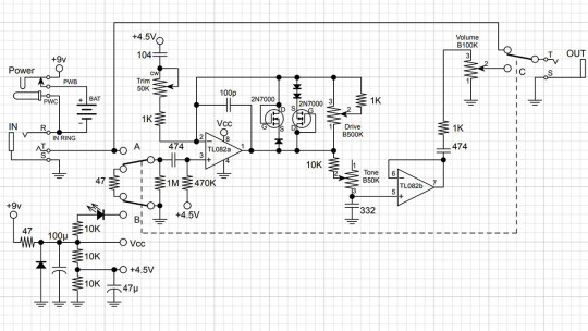
First, the limiter is included in the operational amplifier feedback, that is, between the output and the inverting input, not between the output and virtual ground. That is, here we have a soft limiter.
Secondly, one diode is added in series with each MOSFET. Clipping remains asymmetric: we have one diode in the left arm of the limiter and two diodes in the right arm.
Third, the second operational amplifier is used as a voltage repeater, aka buffer: the output is directly connected to the inverting input.
Fourth, the tone control is implemented a little differently: two OCD`s switchable resistors are replaced by a potentiometer.
And finally, the most critical, fifth difference. A potentiometer is included in the tone correction circuit between the inverting input of the first operational amplifier and the artificial midpoint.
This fourth knob, Voicing, or Character, allows you to smoothly adjust the lower frequencies in the overdrive structure over a wide range, similar to the Resonance control on many tube guitar amps.
The potentiometer is signed as a trimmer in the diagram because some pedal makers don't want to install a fourth knob on the pedal`s body. This is what Landtone did when developing the Phoenix Song Overdrive DIY kit.
The developer suggests installing the trimmer on the PCB, and to access it, you need to disassemble the pedal by unscrewing the footswitch nut and taking out the PCB.
But I will not be lazy to drill an extra hole in the pedal body and install a potentiometer with a knob, connected to PCB by wires instead of the trimmer. Because I consider this regulator simply invaluable and irreplaceable.

Before we get to assembly and testing, let's look at another pedal with a similar adjustment. However, it is based not on the Fulltone OCD but on the Ibanez Tube Screamer.
The Precision Drive

This is a signature pedal by Misha Mansour of Periphery, manufactured by Horizon Devices. Compared to the original Overdrive Pro TS808, the circuit adds a noise suppressor, which we will not consider, and an exciting ATTACK switch.
The Precision Drive scheme was studied and partially replicated by PedalPCB and PCB Guitar Mania. They are manufacturers of DIY kits for guitarists. Their products are called Dwarven Hammer and Collision Drive, respectively. A noise gate is not provided there, but the attack switch is implemented. This is the main difference between Precision Drive and many other overdrive pedals.
In the Fulltone OCD schematic, we saw a resistor switch at the tone shaping circuit in the output section. The Zendrive has a variable resistor in the preamp's RC circuit which is controlling the overdrive structure.
Precision Drive has a constant resistor in the same place, between the inverting input of the overdrive section operational amplifier and the virtual ground, but the capacitors are switched.
This is the same thing: we change the time constant of the RC circuit, which adjusts the audio signal's frequency spectrum. At the same time as the time constant, the complex impedance changes, thus the gain.
A resistor is a resistance to both DC and AC current. At the same time, a capacitor is only resistant to AC current because DC current does not flow through a capacitor. Since DC current does not flow through our RC circuit, there is no difference between adjusting the resistance and switching the capacitance.
But the active/reactive ratio affects the circuit's Quality factor, i.e., its resonance. It's no coincidence that the knob on guitar amplifiers, which adjusts the same frequencies as our potentiometer or switch, is often called RESONANCE. And it is used to adjust to the resonance of the electromechanical system - the loudspeakers in the cabinet, along with the masses of air in and around it.
The reactive impedance accumulates energy and gives it away, except for losses due to dielectric recharging and magnetizing the magnetic core in inductors. This is why coreless inductors are often used in high-end equipment, so-called air inductors. They weigh a lot, take up a lot of space, and are expensive because copper is more expensive than steel. But these are the laws of physics on which technology is based.
Unlike reactive impedance, active resistance converts electrical energy into heat, thus reducing the Q-factor. In some cases, it is necessary and useful. In others, it is harmful. Or it simply creates a unique sound character.
That's why switching capacitors and turning the potentiometer knob in the feedback circuit of an audio frequency amplifier is almost the same thing, but not quite. And it's great that there are such different variants of guitar overdrive pedals!
Landtone Phoenix Song Overdrive
Now you can hear how my Zendrive from the Landtone OD-1 kit sounds, with a Seymour-Duncan SH4 humbucker on a Gibson MM Explorer guitar, into an Orange MT20 with a Torpedo Captor X. And see how I assembled the pedal and also a kitten walking around the table and prancing around.
youtube
I liked the pedal, especially its fourth magic Voicing knob, which does things to the sound that other tone controls can't. I also liked the bird on the body. Because I love birds. And in the music world, the decoration of instruments and hardware plays no small role because it inspires creativity. And the fact that the pedal is assembled by my hands also warms my soul and creates inspiration.
3 notes
·
View notes
Text
The idea is for people who live with someone, and this someone does not know how to knock on the toilet door to check if it is occupied!!!
This is a simple device based on some kind of microcontroller that turns on the red backlight along the contour of the door if the latch is closed, and turns on the green backlight when the latch is open. The latch in this case works as a switch, and the microcontroller checks whether there is power on the pin connected to the latch and thus knows which backlight to turn on.
As a result, we get a demonically red illuminated door that hates this someone who does not know how to knock on this very door!
Even If I dont make it myself, I'll post everything you need for this project.
#demonic door will come to you while you asleep#tech#shittertonpost#diyelectronics#diy tutorial#diy#house idea
2 notes
·
View notes
Text
Raspberry Pi Projects
Raspberry Pi is a tiny computer that packs a punch! It's a single board computer that's small enough to fit in the palm of your hand, but powerful enough to run a variety of projects. Whether you're a beginner or a seasoned pro, there's a Raspberry Pi project for you.
One of the most popular projects for Raspberry Pi is creating your own media center. With software like Kodi, you can turn your Raspberry Pi into a streaming device that can play all of your favorite movies and TV shows. You can even add a touch screen and use it as a portable media center.
Another popular project is creating a retro gaming console. With software like RetroPie, you can emulate all of your favorite classic games and play them on your Raspberry Pi. You can even connect it to a TV or monitor and use it as a standalone gaming console.
Raspberry Pi can also be used for home automation projects. You can use it to control lights, thermostats, and other smart devices in your home. You can even use it to set up a security system or create a smart mirror.
Raspberry Pi is also great for learning to code. You can use it to learn programming languages like Python and Scratch. There are also a variety of educational resources available that can help you learn how to code and build projects with Raspberry Pi.
Overall, Raspberry Pi is a versatile and affordable computer that can be used for a wide range of projects. Whether you're into gaming, home automation, or coding, there's a Raspberry Pi project that's perfect for you. So why not give it a try and see what you can create!
#raspberrypi#DIY#electronics#programming#arduino#codeforbeginners#DIYelectronics#DIYtech#DIYrobotics#DIYcomputers#makermovement#makersgonnamake#DIYscience#DIYengineering#DIYeducation#STEM#STEMeducation#computerscience
2 notes
·
View notes
Photo

LibrePCB 0.1.7 - Measurement tool + Snap points
2 notes
·
View notes
Video
Live at Π6, Athens, July 2022
Spoken Word by Yannis Mihos and electronics.

Group Improvisation
2 notes
·
View notes
Video
youtube
DIY Digital Laser Ruler Tutorial with VL53L0X GY-53, SSD1306, and Wemos ...
#youtube#DIY#digital laser ruler#VL53L0X GY-53#SSD1306#Wemos D1 Mini#Arduino project#laser distance meter#OLED display#DIY tutorial#maker#Arduino development#technology tutorial#Arduino#LaserRuler#ElectronicsTutorial#MakerCommunity#DIYElectronics
0 notes
Text
Mạch điều tốc dimmer 10A DC từ 9V đến 50V chuyên dùng gắn cho mottor điện
#electronicscomponents#diyelectronics#electronicparts#electroniccomponents#arduino#raspberrypi#makercommunity#electronicengineering#diyelectronicsproject#circuitboard#microcontroller#soldering#electronicsprojects#embeddedelectronics#robotics
0 notes
Text
How To Make Electronics Water Diya At Home

Creating a water diya at home is a simple and fun electronics project that anyone can try. Here's a step-by-step guide to make your own water diya:
Gather the materials: You'll need a small plastic or glass container, two metal electrodes (like copper or aluminum rods), a battery, and some water.
Prepare the electrodes: Clean the metal rods to ensure they conduct electricity well. You can use sandpaper or a metal cleaner for this.
Fill the container with water: Pour water into the container until it's about three-quarters full.
Insert the electrodes: Place one electrode on each side of the container, ensuring they don't touch each other.
Connect the battery: Attach the positive terminal of the battery to one electrode and the negative terminal to the other.
Test it out: Once everything is set up, the circuit should be complete, and you should see a small current passing through the water, creating a gentle glow.
Adjust as needed: If the diya doesn't light up, check the connections and make sure everything is securely in place.
Learn More - https://goglobalways.com/blog/how-to-make-electronics-water-diya-at-home/
#DIYelectronics#HomeProjects#ElectronicsCraft#WaterDiya#HomemadeDiya#CraftingAtHome#ElectronicsTutorial#CreativeCrafts
0 notes
Text
Bringing up the Python Camera S3 - PREVIEW ! Espressif ESP32-S3, an open-source digital camera 📸🔧🐍
#adafruit#opensource#opensourcehardware pythoncameras3#espressifesp32s3#opensourcetech#digitalcamerapreview#electronicsengineering#camerainnovation#techreview#pythonprogramming#diyelectronics#electronicscommunity#nextgencamera
39 notes
·
View notes
Text
Devlopment board
#controller#esp32#esp32project#pcb#pcbdesign#pcbassembly#engineer#engineering#electricalengineering#circuits#iot#smarthome#diyelectronics#trending#viral#reels#instagram#instragramreels#followers#boost#explore#explorepage#likeforlikes#electricalengineer#electricalwork#electricalcontractor#electricalhacks#electricallife#electricalsky
2 notes
·
View notes
Text
youtube
Practical Exercise 01 | Step-by-Step: Designing a Half Adder with Xilinx Vivado | VHDL | In Hindi
In this practical exercise, you will be guided through the process of designing a half adder using Xilinx Vivado and VHDL. The step-by-step instructions will ensure that you understand each stage of the design process thoroughly.
youtube
Subscribe to "Learn And Grow Community"
Follow #learnandgrowcommunity
#vhdl#VHDLCoding#fpga#fpgaprogramming#fpgatutorial#vhdlprogramming#vhdltutorial#digitaldesign#XilinxISE#HalfAdderTutorial#handsonlearning#PracticalExercise#digitalcircuits#Learnandgrowcommunity#electronicstutorial#circuitdesign#ISEImplementation#techeducation#DIYTech#FPGAProgramming#techtutorial#engineeringeducation#ExploreDigitalDesign#troubleshootingtips#diyelectronics#codingskills#XilinxTutorial#CreateWithXilinx#techinnovation#circuitcreations
1 note
·
View note
Text

World Electronic Materials Conference
December 16-18, 2024 | Singapore
More information:
electronicmaterialsconference.com
For Enquiry:
[email protected]
#WorldElectronicConference#ElectronicsInnovation#Innovation#DIYElectronics#ElectronicsProjects#Arduino#RaspberryPi#CircuitDesign#ElectricalEngineering
0 notes
Text

I was delighted to be invited to give an artist talk about my practice and also perform at the Quorum based in the ArtsOne Building's Pinter Studio at Queen Mary University in Mile End, London. Quorum is affiliated with the School of English and Drama.
Thank you to Henry, Heath and all the Quorum Committee, and big thanks to David Wright for the technical support on lighting and sound, plus Zoom!
#Quorum#queen mary university of london#Pinter Studio#Dushume#StudioBench#NoiseSelector#DIYNomad#Noise#NoiseMusic#BassCulture#Bassshaker#Glitch#Soundart#Soundartist#LiveElectronics#DIYElectronics#ExperimentalSound#ExperimentalNoise#HarshNoise#noise music#ExperimentalMusic#diymusic#Practice#Performance
1 note
·
View note
Text
Unlock the power of embedded systems with us! 🚀 Dive into a world of innovation and technology where every circuit, code, and connection matters.
Read more: https://livewirecoimbatore.com/
Reach Us: 8870275880
Embedded Systems
#embeddedsystems#electronics#raspberrypi#engineering#arduino#technology#iot#robotics#electrical#arduinoproject#projects#arduinouno#programming#electricalengineering#electronicsprojects#embedded#sensors#diyelectronics#digitalelectronics#microcontroller#artificialintelligence#electronicsengineering#electricians#computerengineering#electronicsquiz#pcbdesign#electricianlife
0 notes
Text
DIY functional oscillators

Signal distortion induced by electronic devices, primarily amplifiers, could be either undesirable or useful.
When we play back an audio recording, we want it to sound as close to the original as possible. Or sometimes, we want to add just a smidge of tube distortion.
On the other hand, magnetic recording on tape and mechanical recording on vinyl, by their nature, significantly alter the sound; therefore, distortions are deliberately added into the circuits of recorders and playback equipment so that, in the end, the resulting audio signal turns out to be indistinguishable from what has been recorded.
In addition, volume controls are equipped with loudness compensation to account for human hearing abilities.
Mobile pocket audio devices have tiny speakers, and their power amplifiers are specifically designed to add bass and limit treble so that the sound is deeper and less squeaky.
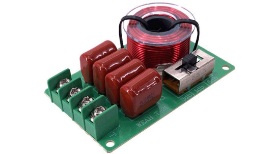
Multi-way speaker systems have filters, and sometimes even separate amplifiers, that slice the sound signal into frequency bands for each dedicated speaker: subwoofer, low-frequency, mid-frequency, and tweeter. These can also be considered deliberately created distortions.
Finally, processing an electric guitar signal requires numerous fine-tuned distortions. They form a wonderful guitar tone. But if we simply plug the best electric guitar into a hi-fi amplifier, we'll be disappointed.
One can also identify a malfunction by the specific distortions of the signal and, by tracking the signal flow, specify the location of the malfunction in a complex circuit.
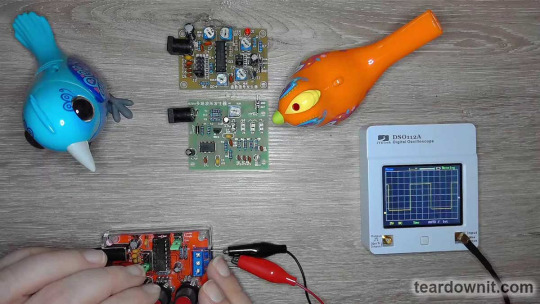
A device that allows you to see distortions is called an oscilloscope. But having an oscilloscope is not enough; we will also need a standard waveform signal generator. Today, we will assemble three such generators.
So-called standard waveforms are sine, triangle, and square. Devices that generate such signals are called function generators.
A sine wave is the simplest signal, but it is the most difficult to create without an LC resonant tank, using only RC circuits. A pure sine wave oscillates one frequency; it is needed to determine the harmonics the circuit adds to the signal.
For example, in this image from the post about the tube amplifier, we see that the upper half-wave is wide and rounded, and the lower half-wave is narrow and pointy. This indicates the presence of a second harmonic, which makes tube amplifiers sound so beautiful.

A triangular waveform could be created by a ramp voltage generator. Such a signal allows one to see nonlinear distortions as lines bend on the oscilloscope screen.

Bending them a certain way brings the triangle line closer to a sinusoid. This is exactly how the function generators on microchips that we are studying today are designed.
An ideal square wave consists of vertical and horizontal lines. Looking at the flow of such a signal, one can see the frequency-dependent deviations, interference, and parasitic processes.
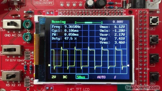
For example, a differentiating circuit with a time constant of an order of magnitude smaller than the period of the input signal creates a sharp peak at the beginning of the horizontal section.

And this is what the result of the operation of an integrating circuit with a time constant comparable to the signal period looks like.
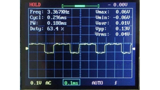
If the integrator time constant is noticeably smaller than the signal period, then only the leading edges become sloped, and the top part of the square wave remains flat. In this oscillogram, we see additional high-frequency interference.
Here, we see not just high-frequency noise but damping oscillations excited by sudden changes in the input signal. Such vibrations are called "ringing".
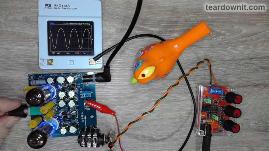
Function generator on the XR2206 chip
Our first generator can produce electrical oscillations with frequencies ranging from 1 Hz to 1 MHz. This is more than enough for an amateur's lab.
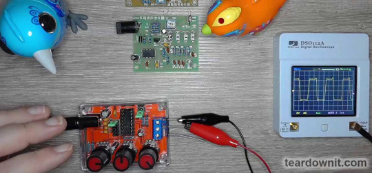
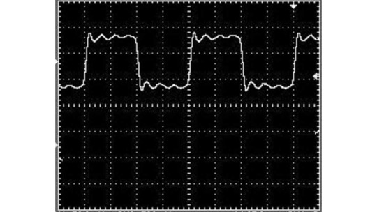
The 300 kHz square wave we have here is distorted not by the generator itself but by the DSO112A oscilloscope, whose analog bandwidth is 2 MHz.

At 20 kHz, the upper limit of the audible range, the square waveform appears almost perfect.
The generator volume knob allows one to crank it up to the limiter. This generator feature must be kept in mind, or the limitation may sometimes seem to occur in the circuit under study.

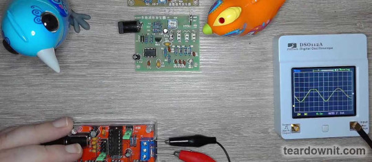
The 400 kHz sine wave looks great. Remember that this is 1/5 of the oscilloscope's bandwidth, so all the harmonics higher than the fifth won't pass through the oscilloscope's analog input.

This is a triangular waveform at a frequency of 130 kHz. The tops are slightly rounded, but the lines are straight. Everything looks as it should.
The generator circuit is elementary. Capacitors C1 and C2 together are a power filter. The square wave output is pulled up by resistor R1 to the power supply positive because it is an open collector output.
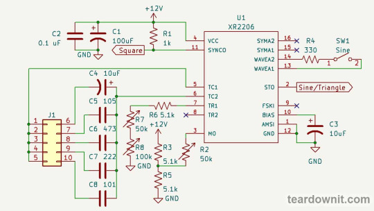
C4-C8 are timing capacitors, and J1 is their frequency range switch.
Timing resistance is made up of three series resistors. R8 is a coarse frequency setting, R7 is a fine setting, and R6 is a limiting resistor, so it cannot be zero.
The circuit has input 8 (TR2) for the second timing resistor. Pull pin 9 (FSKI) to the ground; input 8 (TR2) will become active. If input 8 is left disconnected or pulled to the power supply positive, then input 7 (TR1) is active.
This option allows one to instantly switch between two oscillation periods, which is helpful for frequency shift keying or pulse width modulation.
To get PWM, one needs to connect input 9 (FSKI) to output 11 (SYNCO). Then, the duty cycle will be determined by the ratio of the resistances connecting TR1 and TR2 to the ground, and the frequency will be determined by the sum of these resistances.
Pin 3 (MO) bias setting is the gain adjustment. It is the amplitude of the output signal and is tweaked with a variable resistor, R2.
Pins 13 and 14 (WAVEA1, WAVEA2) are used to form a sinusoid. Output 2 (STO) produces a triangle waveform if they are open. If those pins are connected through a resistor, there will be a sine wave. Its shape can be adjusted by changing the resistance R4.
Input 1 (AMSI) is intended for amplitude modulation. We don't use it in this scheme.
Output 10 (BIAS) is connected to the internal reference voltage source. To ensure its stability and the absence of any interference, a capacitor C3 is connected to it.
You can add a potentiometer to pins 15 and 16 (SYMA1 and SYMA2) and connect its wiper to the ground. Then, it will be possible to further adjust the symmetry of the sinusoid. Although, as we've seen, this is optional.
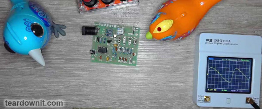
Function generator on the ICL8038 chip
The ICL8038 chip has much in common with the XR2206; it is also designed to create a function generator with minimum external components.
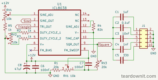
Like the XR2206, the ICL8038 has a timing capacitor on input 9 (TIME_CAP). We switch through five different capacitors to get five frequency ranges.
Square wave output 9 (SQR_OUT) for both microcircuits is an open collector. It needs to be pulled up to the positive power supply. ICL8038 has separate sine and triangle outputs: 2 (SINE_OUT) and 3 (TRI_OUT).
The ICL8038 has only one input for timing resistor 8 (FM SWEEP), so we won't be able to switch between resistors and get FSK.
But inputs 4 and 5 allow one to adjust the duty cycle of PWM. The resistances between these pins and the power supply positive, set by the position of wiper RV2, affect all three outputs.

Resistor RV4, the bias of input 1 (SINE_ADJ), tweaks the vertical symmetry of the sine wave. As we already know, this affects the harmonic series of the signal.

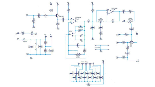
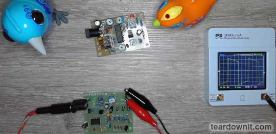
Simple function generator on NE555
If you do not have a specialized chip, a simple square, triangle, and sine wave generator can be assembled in many ways, for example, on a 555 timer.
We see an emitter follower on transistor Q1 at the device's output. It has a positive bias in the form of resistor R10. The input resistance of this stage is about 100 kOhm, so the voltage at the base of Q1 will be about half the supply voltage.

In the first position of the switch, rectangular pulses from the output of the 555 timers pass through series capacitors C4 and C5 and parallel capacitor C6. Resistor R3 is connected with C4, and R4 is connected in parallel with C6.
The result is a hybrid of a rectangle and a ramp with decent linearity. One can evaluate the distortion and parasitic oscillations it introduces by comparing the original waveform with what is produced in a particular circuit.
Next comes the integrator R5C7, after which crescent-shaped relaxation oscillations are obtained. The authors labeled this waveform a sawtooth or ramp, but it's more like shark fins.

After the second similar integrator, R6C8, a hybrid of a triangle and a sine wave is created: the tops are rounded, but the inclined sections are almost linear.

And finally, after the transistor stage on Q2, shunted by capacitor C9, we get an excellent approximation of a sinusoid. Resistor R8 provides base bias to Q2.

So we've seen what capacitors, resistors, and a transistor do to an electrical signal, and we learned how to build a simple generator with recognizable waveforms that can be used to study distortions in electrical circuits.
It is not that difficult to assemble a proper function generator on a special microcircuit. Still, it will definitely have more functions and better signal quality.
Professional-grade devices are, of course, more advanced, but they have a much higher price and substantially bigger dimensions. Unlike the three simple generators we've assembled and tested today, not every electronics enthusiast can afford them.
youtube
0 notes
Last Seen Blogs