#dot matrix printer
Text

Seikosha SP-1000VC dot matrix printer for Commodore computers
54 notes
·
View notes
Text
So I have this printer ...

Not that one specifically, that one is beautiful and in great condition, but one like it — Apple ImageWriter II. Specifically mine is the ImageWriter II/L variant, the last revision of the ImageWriter II line, but it looks like this one.
Or at least it did once upon a time.
My family acquired this printer second-hand in the late 90s along with a Mac Classic. It got used regularly for school reports and letters and business documents and tax forms for a few years until we finally were able to get a new computer with a color inkjet printer.
Long story short, like the computer that went with it, ultimately this poor printer ended up sitting in storage without air conditioning in East Texas heat and humidity for nearly twenty years. It's a sad story of slow decay.
My ImageWriter is now yellowed and scuffed and scraped and rusted and missing a piece or two; just a dim reminder of its former beauty. Given the state of it, what hope do we have of ever again hearing it sing the song of its people?
Well, I'm not going to let it go without a fight. Time to dig in and see what we can ...
... oh. Oh dear that won't do at all.
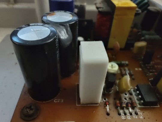
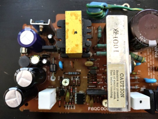
A good rule to follow when working with these 30+ year old systems, is to (carefully!) open and inspect before applying any power. In this case I'm very glad I did. Three large filter capacitors on the power supply have very obviously swollen and burst, spreading their corrosive bile all over the neighborhood.

The back side of the power supply circuit board was a wasteland of rotting solder mask, corroded traces, and displaced silkscreen. The electrolyte has eaten its way down the leads, through the solder, and left carnage in its wake all across the bottom of the board.


First order of business is getting those old capacitors removed from the board so cleanup can begin. If you've never worked with hardware of this vintage, a fair warning — make sure you're working in a well-ventilated area. Sure the solder has lead and the flux ain't great for the lungs, but the big concern here is the unholy stench of heated capacitor electrolyte hitting the nostrils like the revenge of Poseidon's refuse bin. The local fish market has nothing on these things.
The old solder, especially when mixed with the electrolyte, tends to behave in a very un-solder-like fashion. It will refuse to melt and when it does it will slump around like wet sand rather than flow like liquid metal should. While it may seem counter-intuitive, the best way to get rid of it is to add more fresh solder to it. On these single-sided boards with large components like this, a spring-action solder pump works well for getting the old parts removed, and then some solder braid will clean up the pads well.
Once the old parts are out, I like to thoroughly clean the area with isopropyl alcohol to remove the electrolyte and years of grease and dirt and pet hair that may have cemented itself to the board. In this case I also needed to use a mild abrasive to remove that damaged solder mask where it had bubbled up off the corroding copper traces. I was lucky here that none of the traces were actually broken or corroded through completely. Clear nail polish works well for protecting the now bare copper (just make sure it's not the UV-cure gel stuff).
From here I turned my attention to the case, because the power supply is the last item removed and first installed when conducting a complete tear down of this printer, and it didn't make sense to put my newly cleaned power supply into a dirty old case.


I'm not really a fan of retrobrite, and these large case pieces would be a real challenge anyway. So all I want is to clean up the dirt and rust and as many scuff marks as I can. As far as I'm concerned, the rest is just part of the history of the item. Each mark tells a story of how this item was used, not just put up on a shelf to be looked at. And if I didn't have any interest in using the machine until it completely falls to pieces, I wouldn't be bothering with going fishing replacing old capacitors.
This is a good point to do some testing. There may still be more wrong with that power supply. Output voltages could have drifted out of spec from other components aging, or maybe I installed capacitors that don't quite match the originals. The ImageWriter II/L power supply has three outputs — +5VDC, -5VDC, & +26VDC. With no load on the power supply, I measured the outputs at around ±7V and 30V. That seems high, but it's not outside of what I would expect for a power supply that's not actually driving anything. This would be a good point to use an adjustable test load, but since I don't have one of those, I'll just have to move forward with my "well it seems fine'
Spoiler: it was not fine.
As part of its startup sequence, the ImageWriter exercises all of its stepper motors to get everything to a known state. This high current draw immediately after power on was more than its old power supply could give. There's clearly more than bad capacitors on the supply, but identifying what exactly is still beyond my current skill level.
So in the interest of getting the machine working (because I have plans for it), I opted to try replacing the power supply with something more modern. The catch here is the odd assortment of voltages the original supply provided. It's easy to find a ±5VDC supply, but 26V is virtually unheard-of.
Apple's documentation for the printer mentions the +26V supply is for driving the motors. I suspected that the 26V supply was less carefully regulated and probably targeting something more like 24V. Sure enough, the stepper with the highest voltage rating on its label was 24V. With a little extra current capacity available, I figured the printer would function just fine with a 24V supply.
The catch is, 24V & ±5V is not a common configuration. There are plenty of 12V & ±5V supplies, but that won't do here. I settled on a Mean Well 24V & 5V supply with a -5V inverter ... And promptly ordered the wrong part. I had a nice new 12V & 5V supply. That's ok, once I got it in hand it was a bit too large to fit in the space I had anyway.
So I got a different Mean Well 24V supply and a separate 24V-5V DC-DC converter. It's a bit of a mess all crammed into the bottom of the case, but it should give all the right voltages (or near enough).

I did have to remove the power switch from the old supply though. That particular part has long since been discontinued, and compatible replacements proved difficult to find.
Now that it's all assembled, it's time to test. This is the part that always makes me nervous, especially when dealing with mains voltages. There's so much that can go so very horribly wrong.
I started out with a smoke test — switching on power briefly to make sure there were no direct shorts that might cause an explosive failure. No smoke is a good sign, so check the voltages. With no load, the new supply rails read 23.99V, 5.00V, and -5.55V. That's about as good as I could ever ask for. So now there's only one thing left to test … does it actually print?
Success!
It's not perfect. Every once in a while it will stutter while printing and get stuck with the carriage on one side or the other. It really needs a complete disassembly, thorough cleaning, and relubrication. That kind of mechanical teardown is a bit beyond what I'm comfortable with at the moment, but I'll happily settle for mostly working over not working at all.
#vintage computing#macintosh#imagewriter#imagewriter ii/l#computer repair#apple#apple computers#dot matrix printer#mean well#it's always the power supply#power supply
40 notes
·
View notes
Text
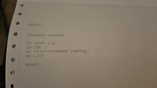
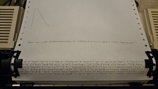
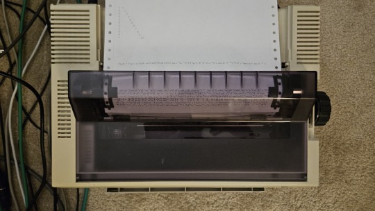
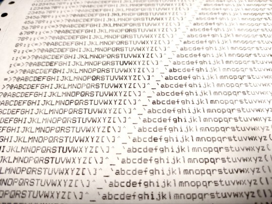
How to dot matrix ascii art.
#dot matrix#ascii art#asciiart#retro tech#retrotech#oldschool#80s#90s#vintage#vintage hardware#dotmatrix#dot matrix printer#floppy disks#floppy disk#nostaliga#retrocomputing#retrocomputer#linux#command line#commandline#terminal#linux terminal
24 notes
·
View notes
Text
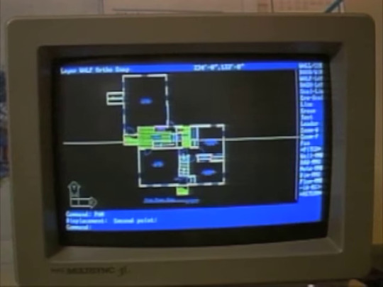
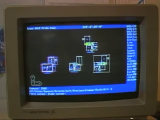
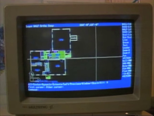
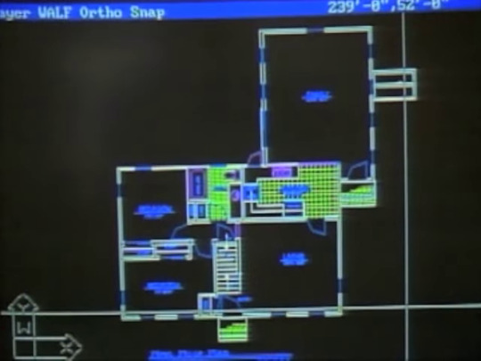
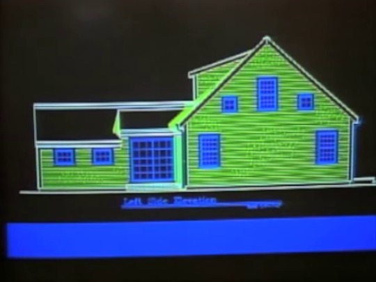
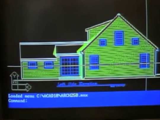
What a lovely display of early 90's computer-aided design. A digital blueprint for building/remodeling a house in Marston Mills, MA (USA). The screenshots are taken from Episode 1 of Season 1 of "Home Again with Bob Vila" a weekly syndicated home-improvement program that aired for 16 seasons from 1990 to it's cancellation in 2007.
#technology#computers#old computers#retro tech#oldtech#crt#retro computing#old tech#retro#retro computers#vintage tech#1990#90s#techcore#retrocomputing#dot matrix printer#architecture#blueprint#rendering#computer art#computer graphics#image processing#digital#digitalillustration#bob vila#home again#old tv#television#home improvement
16 notes
·
View notes
Photo
30 notes
·
View notes
Text
#ambition#ambition (1991)#movie#spoiler#the sound of a#dot matrix printer#grinding away#all throughout the climax#it's the background audio#for the entire scene#my gifs#540px#10mb#Old computer tech delights me tho#even the sounds
0 notes
Text
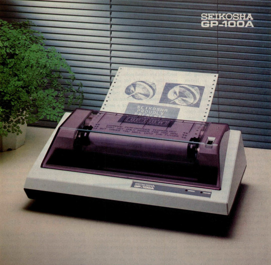
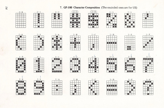
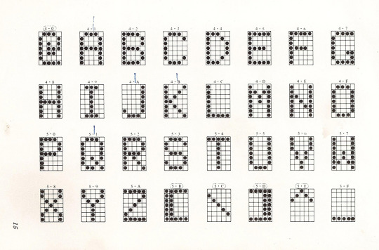
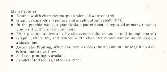
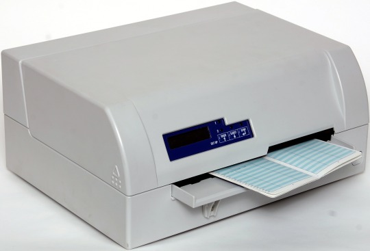
Seikosha GP-100A printer
Byte Magazine - Dec. 1982: archive.org
Owner's manual: archive.org
#Seikosha#Seikosha GP-100A#Seiko#retro tech#retrocore#dot matrix#printer#80s tech#vintage electronics#retrowave
88 notes
·
View notes
Photo

Essential 90s-movie set dressing for “forgetful tech-savvy Dad”
#thrifting#shiftythrifting#masterpieces of the dot matrix printer#turn on answering machine DAD#in frames#hall of fame#analog life
917 notes
·
View notes
Text
Domestic Bees pt. 1
Yang: You Crumb-filled toaster!
Blake: Yang...
Yang: You half-bit dishwasher!
Blake: Yang.
Yang: You glorified waffle iron!
Blake: Yang!
Yang: Your mother was an 8 -inch floppy disk, you Dot Matrix Printer!
Blake: YANG!
Yang: What?!
Blake: It's a roomba. The bin is probably full.
Yang: *stops disassembling the roomba in anger* ....I knew that....
#bumbleby#domestic bumbleby#how to insult robotics#roombas are dumb#yang xiao long#blake belladonna#10 points to whoever knows what a floppy disk or dot matrix printer is
95 notes
·
View notes
Text
robofuckers will be like "DILF" and then the DILF in question is this
7 notes
·
View notes
Photo
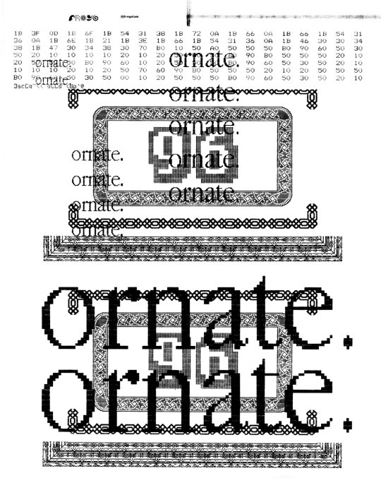
ornate. (2021.12.13)
created by multiple overprints on a dot-matrix printer
139 notes
·
View notes
Text
“The kids these days, they don’t remember when the printers screamed!”
somewhat incoherently shouted to my mother as we shop for computer parts
#honestly it’s not just the dot matrix printers#though they did make quite the fuss when you pestered them for work#but I remember until like 2007 even basic printers screamed like a banshee#you set it to print then ran to another room
12 notes
·
View notes
Photo
259 notes
·
View notes
Text
Wacky Workbench Good Future (JP)'s theme is the concept of adorableness distilled in audio form. I listen to it and I'm just like

p e r f e c t t e c h n o (dial-tone and xylophone noises)
#I love how they used real-world machines in the song compositions like telephones and dot matrix printers#in addition to being quintessentially 90s it gives the impression that technology can be as wondrous as nature#and is not inherently evil#technology when used responsibly can be a great boon to our world#it's a much more nuanced message than the strict environmentalism of western media at the time#sonic cd
8 notes
·
View notes
Photo
101 notes
·
View notes
Note
Reading accounting stories to my mom (who works/has worked in the field or related ones). I mentioned the lotus notes thing and my mom immediately replied, “That’s old!!!!”
i noticed it the first time he needed me to come in and confirm that a popup was fake and not a windows alert, and it took me a minute to figure out what i was looking at
#original#shoutout to the guy who they have come in to do tech stuff#who had to install lotus notes on a brand new windows 10 pc without flinching#he also had to explain that the new computer would not work with his dot matrix printer and he had to get a new one
62 notes
·
View notes
Last Seen Blogs