#inner diameter testing
Text
TP316L-7.96mm*4.6mm Stainless steel electropolished tube for making chromatographic column,inner diameter testing with plug gauges
#stainless steel tube#electropolished tube#plug gauges testing#4.6mm tube#Chinese manufacturer#Chinese producer#inner diameter testing#chromatographic column
2 notes
·
View notes
Text
I'm going to tell you how I made Michelangelo's cape!
In case you don't know Michelangelo is @weird-profiterole's oc. And we decided to send each other goodies from our country. Well I decided that as a surprise I'm making her Michelangelo's cape!
This is what I have to go off of. I would add a pic directly but I respect wifey and won't repost her art. But that post gives details about her oc and details of the cape.
At the time of starting it she didn't have the back designed at all. Just constellations that Michelangelo embroidered himself onto the cape.
SO WHAT DID I DECIDE TO DO?
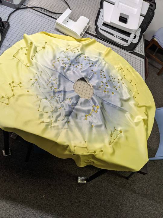
The whole arctic circle

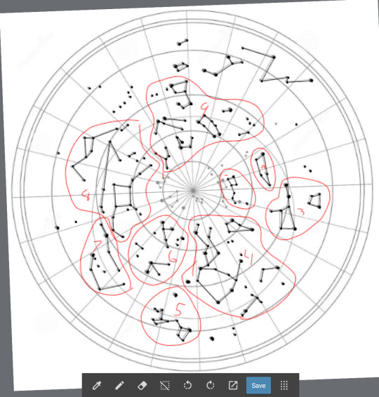

I divided all the constellations into 10 manageable sections. Anything in the most inner circle wouldn't fit however. I did move the Big Dipper down to be able to add it however.
Side note: Michelangelo's cape is NOT A CIRCLE CAPE. But since there wasn't a back to the cape, I had to make a creative decision, and since I didn't want Marine to know about it, I couldn't ask questions. But I figured it wouldn't be too much of an issue. He has more than one cape after all.
So I make all 10 sections into embroidery files. I draw them out myself with the template above to get all the placement correct. I even pulled out my astronomy notes from 11th grade to look at my star chart and relearned how to read it and everything.
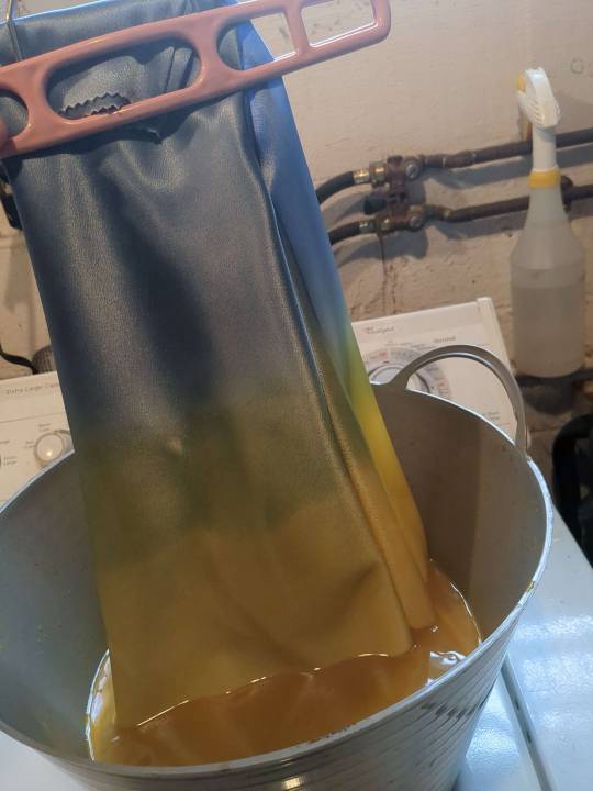
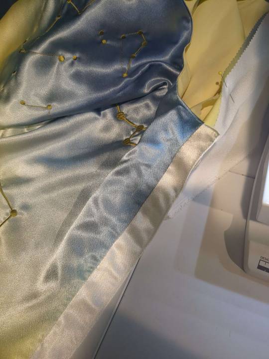
Then I got the fabric. Just a white polyester satin. Something light with a nice drape. But here came the fun and time consuming part. DYING IT.
Now I love to dye fabric. LOVE. But a dark blue to a bright yellow with a minimal amount of green? I knew it wasn't going to be easy. So I cut out my circle like you would a circle skirt. The diameter being about 50 inches. Then I start with the the yellow.

Great, looks good. Then I wash it to get the excess dye it and it becomes a pale yellow. I need something vibrant. So I do it again. And again. And again. And again. And again eight more times. Finally I get it tot he point where I'm good with so I flip it around to do the blue. Well guess what I discovered. Blue dye is really purple. I knew black dye was purple, but I didn't know blue dye was.
Keep in mind I'm using Rite Dye Synthetic. I've never had luck with this dye but I gave it the benefit of the doubt. I shouldn't have. I have All Purpose Rite Dye in a few shades of blue and I do a small test. Those are all purple as well. Now I've already dyed the "blue" part about 4 times at this point and I'm wondering if it just won't take any more dye. But I know that's not the case. I've dyed enough fabric to know that's not the case.
My process is that I dye it for around an hour or two, moving it in the pot about every 15-20 minutes to make sure to get an even gradient. Then I hang it up to dry it, next day I wash it by hand in cool soapy water to get the extra dye out, and then it comes out too pale.
I made a few oopsies along the way, like forgetting to wet all the fabric , meaning the blue went too far into the yellow, ruining the yellow, so I then had to redye the yellow. I once washed the blue three times and then on the fourth washed the whole thing at once (I only wash by hand) and the yellow got a green ting to it.
A month and a half go by and I'm repeating the dye-dry-wash-dry pattern everyday. Then I finally realize I'm going to have to use IDye Poly. Which I knew I should have used to begin with.
Side note: the lines are a lot harder on camera than irl.
IDye Poly is what I recommend using when dying anything. The color is EXACTLY what it is on package, but its a powder, so you have to use all of it, and it SMELLS. Oh fuck it smells. They say to use the stove top method but I just put boiling hot water in a metal pot then put the fabric in. I dyed the yellow twice and it was the perfect shade.
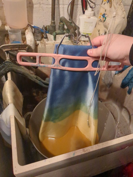
Now for the blue. I knew the blue was really a blue and not a purple. I used that blue before. But to make sure it was as dark as I wanted it to be, I put half the amount of water in and the whole packet of dye and stirred it up. The lines were harsh at first but while dying I also run water over it to clean up the lines. The blue took about four dye rounds and it was finally at the point where I could be happy with it. I wish it was a little darker, but the transition is just how I want it. Because even thought its an ombre, I need a minimal amount of green.
TWO MONTHS LATER and I finally get this
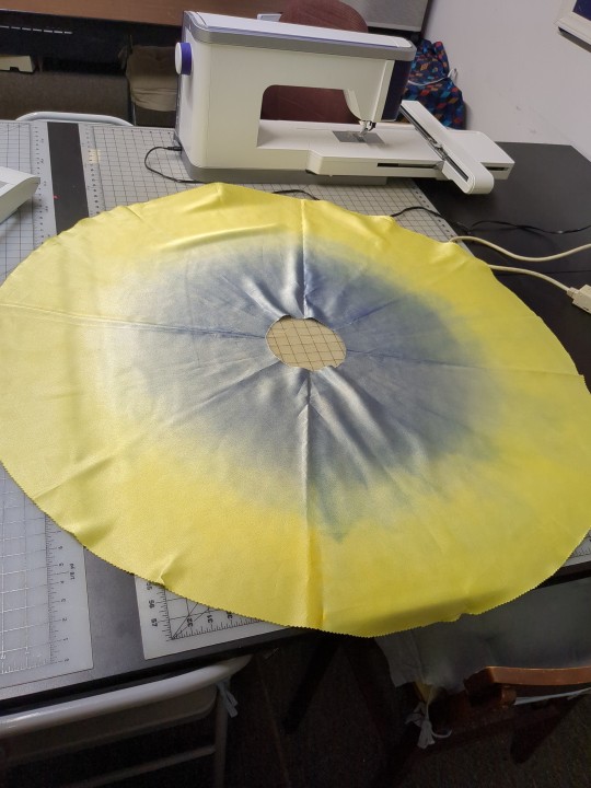

There was some messy party once I unfolded it all but I told myself ITS FINE. REMEMBER ITS THE FUCKING RENAISSANCE. The blue is darker irl than int he picture.

So then I cover it in interfacing to draw out placement lines. This is when I remembered that I haven't even tested my embroidery files yet. I could have been doing that while I was dying the fabric. But I think part of me was scared that this was going to fail and I didn't want to get too deep, even though two months of dying a single piece of fabric is a little deep.
So I got out a Pfaff Creative Icon 2 and uploaded my files and started embroidering.
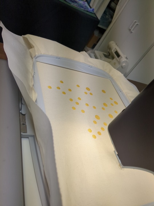


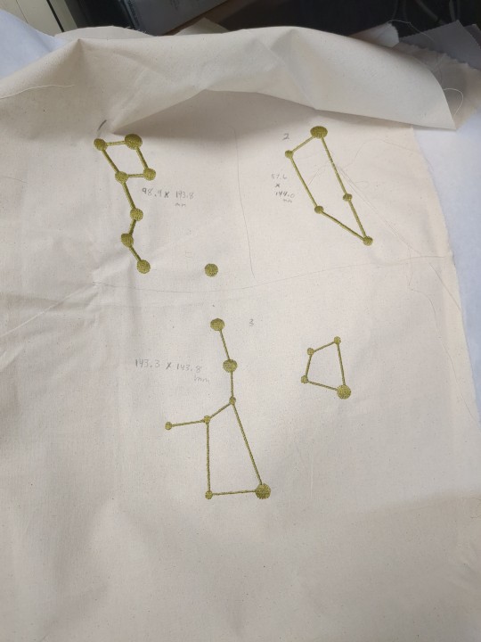

I then cut them out, laid out the cape and started placing them. I knew I was going to have to make some of the files bigger because I wasn't quite sure what I was doing when making them, but I knew I was going to test them so it was okay.

There are only four that really need to be enlarged, but I did make all of them bigger to fill in some gaps. The harsh line in the front is where the opening is going to be.
So after fixing the files and a seven hour day at work it is all embroidered!
Each dot takes about a minute each, plus then the lines connecting all of them. There are some awkward empty spots and I was going to fill them in with stand alone dots/stars, but I decided not to since they weren't on the star chart.
Now I had to rip all the stabilizer off and trim all the threads. Kiki decided she wanted to help

I decided to line it with a pale yellow broadcloth to encase the edges, stitched along the edges to keep it from turning over and then I had the white strips in the front to add. I just used the same fabric since I had extra and since it was white.
You can't tell on camera but after ironing the fabric the color in some areas got darker. It's fairly subtle but I tried to iron the whole thing lightly to even out the color, luckily it darkened the color rather than lightening it.
Now all I had was the tassels and rope. I got it laid out how I wanted it but then didn't have a clue how to attach it, plus the ends of the rope kept fraying and burning the edges gave it a burnt look, plus it was untwisting. So I wrapped a gold embroidery thread about it, and then coated that in a fabric glue so there wasn't much of a chance of it coming undone. I put a button on the back of the cape so that it wouldn't pull at the fabric when I attached it.
AND THEN ITS DONE!

I think the file is too big, but I have a video of it that I will link to show you a 360 look of it.
AND IF YOU READ THIS FAR THANK YOU.
(at the time of writing this I'm praying the package get's to Marine safely)
~~
Shoutout to @lulu-the-smol-floof @legalize-arson @ivoryclive for dealing with all the picture spams and ranting about how worried I was through this whole project
#ikevamp#ikemen vampire#ikevamp oc#ikevamp michelangelo#astrology#fashion#costume design#fashion design#long post#sorry its so long#i really didn't think it would end up being so long#but there's also a lot of pictures
41 notes
·
View notes
Text

Best Greetings
Why Does Jupiter Diameter Equal = 8 Planets Diameters Total?
Jupiter Diameter Equation Analysis
Let's remember the planet diameter equation
Planet Diameter Equation (v1/v2)= (s/r)= I
v = Planet Velocity
r = Planet Diameter
s= Planet Rotation Periods Number In Its Orbital Period
I= Planet Orbital Inclination (example, 1.8 degrees be produced as a rate 1.8)
v2, s, r and I are belonged to one planet and v1 is belonged to another planet
The planet (v1) is defined by test the minimum error
Earth Equation uses Neptune velocity
Mars Equation uses Pluto velocity
Jupiter Equation uses the Earth moon velocity
Saturn Equation uses Mars velocity
Uranus Equation uses Neptune velocity (As Earth)
Neptune Equation uses Saturn velocity
Pluto Equation uses the Earth moon velocity (As Jupiter)
(The Equation works from The Earth To Pluto) (the discussion explains the reason)
THE EQUATIONS
Jupiter equation (10500/142984) = 13.1/(27.78 x 2π) = 0.0734 (error 2.2%)
10500 = Jupiter rotation periods number in Jupiter orbital period
142984 km = Jupiter diameter
13.1 km/s = Jupiter velocity
27.78 km/s = The Earth Moon velocity
4331 days = Jupiter orbital period (and Jupiter rotation period =9.9 hours)
Pluto equation (14178 /2390) = 27.78/ 4.7 =5.9
14178 = Pluto rotation periods number in Pluto orbital period
23908 km = Pluto diameter
27.78 km/s = The Moon velocity
4.7 km/s = Pluto velocity
90560 days = Pluto orbital period (and Pluto rotation period =153.3 hours)
(1)
We remember (SV for Jupiter) = (10500 x 13.1) = 137550 and
(SV for Pluto) = (14178 x 4.7) = 66632 = 137550/2 (error 3%)
And also (SV for Pluto) = 2π (SV for the Earth)
This discussion proved the transportation of motion among the planets
(2)
Jupiter and Pluto diameters equations use the moon velocity because the equation depends on the moon motion and Jupiter and Pluto are the equation terminals that shows the transportation of motion creates the data of the two planets to be suitable for the planet diameter equation using
(3)
We remember the rule (AB =constant) for the planets diameters
Where (Jupiter diameter x Pluto diameter) = (AB) and all planets diameters are defined based on this value (AB)
that shows the data is connected between the two planets
Notice
Jupiter equation produces 0.0734 = 1/13.6
13.6 = Mars diameter equation result (10.2) x 1.3 (Jupiter orbital inclination)
And
5.9 x 4.7 (Pluto velocity) = 2 x 13.6 (error 2%)
This data shows Jupiter equation result is connected with Mars and Pluto because these are the 2 migrant planets and Jupiter tries to repair the negative effects on the solar system design resulting by the planets migration.
Notice No.(1)
Jupiter connects itself with the three inner planets (Mercury, Venus and the Earth) by the following data system
Mercury moves in its day period (176 solar days) a distance =720 million km = Mercury Jupiter distance
And
Venus Jupiter distance= 671 mkm and Venus orbital circumference =680 mkm (1.2%)
And
Earth Jupiter distance= 929 mkm and Earth orbital circumference =940 mkm (1.2%)
(the distance 929 mkm is created when the Earth and Jupiter be on 2 different sides from The Sun where 929 mkm =149.6 mkm +778.6 mkm).
And
Jupiter connects itself with the three outer planets (Saturn, Uranus and Neptune) by Jupiter motion for the distance (2.54 million km) by which Jupiter defines the period 53.9 hours to be the four planets rotation periods total
By that Jupiter made itself the central point of the solar system design.
Notice No.(2)
13.1 (km/s) x 142984 sec = 29.8 km/s x 17.2 h x 3600 = 9.7 km/s x 53.9 h x 3600 = 4.7 km/s x 400000 sec –where
13.1 km/s = Jupiter Velocity 4.7 km/s =Pluto velocity
29.8 km/s = The Earth Velocity
9.7 km/s = Saturn Velocity
142984 km= Jupiter diameter
17.2 h = Uranus Rotation Period
53.9 h = The Four Planets Rotation Periods Total
The data tells Jupiter diameter is used as measurement to define the planets diameters total- also we understand the motion is connected because
the Earth velocity = π Saturn velocity = 2π Saturn velocity
Thanks a lot – please read
Physics Nobel Prize For Imaginary Ideas!
or
Gerges Francis Tawdrous +201022532292
Physics Department- Physics & Mathematics Faculty
Peoples' Friendship university of Russia – Moscow (2010-2013)
Curriculum Vitae https://www.academia.edu/s/b88b0ecb7c
E-mail [email protected], [email protected]
ORCID https://orcid.org/0000-0002-1041-7147
Facebook https://www.facebook.com/gergis.tawadrous
VK https://vk.com/id696655587
Tumblr https://www.tumblr.com/blog/itsgerges
Researcherid https://publons.com/researcher/3510834/gerges-tawadrous/
Google https://scholar.google.com/citations?user=2Y4ZdTUAAAAJ&hl=en
Livejournal https://gerges2022.livejournal.com/profile
Pocket https://getpocket.com/@646g8dZ0p3aX5Ad1bsTr4d9THjA5p6a5b2fX99zd54g221E4bs76eBdtf6aJw5d0?src=navbar
PUBLICATIONS
box https://app.box.com/s/47fwd0gshir636xt0i3wpso8lvvl8vnv
Academia https://rudn.academia.edu/GergesTawadrous
List of publications http://vixra.org/author/gerges_francis_tawdrous
Slideshare https://www.slideshare.net/Gergesfrancis
#математика#русский tumblr#quantum physics#physique#astronomy#астрофизика#квантовая физика#наш физик легенда#физика#космос наука#physics#astrophysics#учеба#ошибки#scientists#science#10 класс#mathematics#maths#школа#русская школа#русский тамблер#решение задач#задачи#механика#quantum mechanics#science side of tumblr#философия#philosophy#электричество
3 notes
·
View notes
Photo


First image of a black hole expelling a powerful jet An international team of scientists led by Dr. LU Rusen from the Shanghai Astronomical Observatory (SHAO) of the Chinese Academy of Sciences has used new millimeter-wavelength observations to produce an image that shows, for the first time, both the ring-like accretion structure around a black hole, where matter falls into the black hole, and the black hole's associated powerful relativistic jet. The source of the images was the central black hole of the prominent radio galaxy Messier 87. The study was published in Nature on April 26. The image underlines for the first time the connection between the accretion flow near the central supermassive black hole and the origin of the jet. The new observations were obtained with the Global Millimeter VLBI Array (GMVA), complemented by the phased Atacama Large Millimeter/submillimeter Array (ALMA) and the Greenland Telescope (GLT). The addition of these two observatories has greatly enhanced the imaging capabilities of the GMVA. "Previously, we had seen both the black hole and the jet in separate images, but now we have taken a panoramic picture of the black hole together with its jet at a new wavelength," said Dr. LU. The surrounding material is thought to fall into the black hole in a process known as accretion. But no one had ever imaged it directly. According to LU, the ring that was seen before was becoming larger and thicker at the 3.5 mm observing wavelength. "This shows that the material falling into the black hole produces additional emission that is now observed in the new image. This gives us a more complete view of the physical processes acting near the black hole," said LU. The participation of ALMA and GLT in the GMVA observations and the resulting increase in resolution and sensitivity of this intercontinental network of telescopes has made it possible to image the ring-like structure in M87 for the first time at the 3.5 mm wavelength. The diameter of the ring measured by the GMVA is 64 microarcseconds, which corresponds to the size of a small (5-inch/13-cm) selfie ring light on Earth as seen by an astronaut on the Moon. This diameter is 50 percent larger than what was seen in observations by the Event Horizon Telescope at 1.3 mm, in accordance with expectations for the emission from relativistic plasma in this region. "With the greatly improved imaging capabilities by adding ALMA and GLT into GMVA observations, we have gained a new perspective. We do indeed see the triple-ridged jet that we knew about from earlier VLBI observations," said Thomas Krichbaum of the Max Planck Institute for Radio Astronomy (MPIfR) in Bonn. "But now we can see how the jet emerges from the emission ring around the central supermassive black hole and we can measure the ring diameter also at another (longer) wavelength." The light from M87 is produced by the interplay between highly energetic electrons and magnetic fields, a phenomenon called synchrotron radiation. The new observations, at a wavelength of 3.5 mm, reveal more details about the location and energy of these electrons. They also tell us something about the nature of the black hole itself: It is not very hungry. It consumes matter at a low rate, converting only a small fraction of it into radiation. According to Keiichi Asada from the Institute of Astronomy and Astrophysics of Academia Sinica, "To understand the physical origin of the bigger and thicker ring, we had to use computer simulations to test different scenarios. As a result, we concluded that the larger extent of the ring is associated with the accretion flow." Kazuhiro Hada from the National Astronomical Observatory of Japan noted that the team also found something "surprising" in their data. "The radiation from the inner region close to the black hole is broader than we expected. This could mean that there is more than just gas falling in. There could also be a wind blowing out, causing turbulence and chaos around the black hole," said Hada. The quest to learn more about Messier 87 is not over, as further observations and a fleet of powerful telescopes continue to unlock its secrets. "Future observations at millimeter wavelengths will study the time evolution of the M87 black hole and provide a polychromatic view of the black hole with multiple color images in radio light," said Jongho Park of the Korea Astronomy and Space Science Institute. TOP IMAGE....Artist’s conception shows a close-up view of the accretion flow and the jet emerging from the black hole region in Messier 87 CREDIT Sophia Dagnello, NRAO/AUI/NSF CENTRE IMAGE....Millimeter-VLBI image of the jet and the black hole in Messier 87, obtained with the GMVA array plus ALMA and the Greenland Telescope CREDIT LU Rusen, SHAO; E. Ros, MPIfR; and S. Dagnello, NRAO/AUI/NSF LOWER IMAGE....Map of the radio telescopes used to image Messier 87 at 3.5 millimeters in the 2018 Global Millimeter VLBI Array (GMVA) campaign CREDIT Helge Rottmann, MPIfR
8 notes
·
View notes
Text
Grommets in progress!

Grommets in armscyes!

Grommets all completed!

Grommets all laced up!

Grommets!
Stabbing holes in a nearly-completed project you've been working on for seven months is always nerve wracking, and even more with this delicate silk brocade. And even more while trying to pattern-match at center back. But I did a test run of setting the grommets in scrap of fabric, I measured and marked the placement carefully, I took my time setting them, and I'm really happy with how they came out.
The lacing is the rayon cording I posted about dyeing the other day, and I'm still just so pleased with the color match I was able to achieve by mixing colors of Rit dye and only keeping it in the boiling pot for about 5 minutes. (My first attempt I actually dyed far too dark by thinking I needed to boil it for 20 minutes, but thankfully I have 144 yards to work with and won't need anywhere near that much.)
Since I decided not to try to hide a zipper in this and keep it as screen-accurate as possible, the back lacing will actually be the way I get in and out of the dress. So to make lacing it up a lot easier I handsewed a lacing point to each end of the cord -- actually just 3mm spiked beads that are meant for jewelry making, but are perfect for threading through the 5mm inner diameter of my grommets. They have just enough weight to move nicely too, so I'm going to use them in the front semi-decorative lacings too.
My goal for this weekend was to get through all the pounding of setting the grommets during non-work hours, and even taking my time and taking breaks as needed, I got through that no problem. Next weekend I want to be able to have everything ready so Jack can help me mark out where the hem needs to go, so all my next steps are going to be focused on preparing for the hem:
I think having the sleeves laced on and the dragon claw lacing at the front waist may change the way the dress falls, so I want to get those done next up. I need to fiddle with my (very well broken in) shoes so they're ready to wear for the fitting. I need to cut ~100" of silk organza to face the hem with, and there's one little fit adjustment at center front I would like to do if I have time, but probably won't affect the hem at all.
If I get all the way through that with time to spare before Saturday morning, I'll spend the rest of the time finishing all the raw edges of the organza underdress. It's in an okay state to wear for fitting the hem, but getting those raw edges handled will make it a lot more comfortable to wear. And hey, it needs to be done eventually anyhow.
The hem is the last big must-be-done for this cosplay to be wearable, and then I'll be able to shift gears into things like the wig, a little bag to carry my con essentials in, finishing the underdress, and the beading the neckline trim. And working on my Swiftie Harley Quinn! Getting that one into a wearable state will probably come before the beading for this cosplay.
I have 44 days left to work on all my cosplays before it's time to pack for Dragon Con, but now that I've actually been able to try this on with the back fully laced up, my to-do list feels a lot more achievable. I've got to keep up this pace, especially if I want to do detail work like beading, but I'm hopeful I can get it all done.
3 notes
·
View notes
Text
Week 1
This week we were set 3 tasks in which we were tested on our ability to use our design tools correctly and accurately. I enjoyed learning how to use these tools as I can see how this knowledge will make my practical design sketching easier and faster in the future. I learnt how to use a tee square, specifically how to line up my paper with the desk or workspace and do quick and accurate horizontal and vertical lines. I also found out that when using the circle template I should use a one mm larger diameter circle when using an art liner ink pen due to the thickness of the line.

figure 1.
My strength was measurements with straight lines and angles when drawing this star. My area of improvement would be pen control to not create a pooling of ink as seen on the leftmost point's inner line. I also had messy sketch lines so I decided to rub them out. I will aim to sketch more precisely to keep these guidelines in my drawing to portray the accuracy of my sketch.
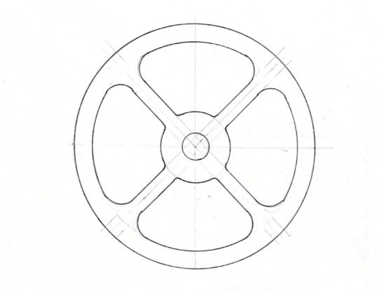
figure 2.
For this exercise, I had a few issues, mostly with the circle template. The instructions were in radii, whereas the template was measured by diameter. This tripped me up as I did not double the radius length to get the diameter and had to restart the curves inside the circles as they were too small.

figure 3.
I measured this shape on tracing paper and then cut this shape out and used it as a template for all the coloured shapes. I realised I should have done my template one mm smaller to make my coloured shapes accurate. You can see the error in this measurement on the top left where the shape corners of orange and yellow do not meet.
11 notes
·
View notes
Text
Huawei’s next-gen MAGICS LH long-haul microwave solutions

Microwave Networking solutions
In Baotou, Inner Mongolia, the China Unicom Inner Mongolia Baotou Branch and Huawei have successfully conducted the first-ever commercial test of the ground-breaking MAGICS LH long-haul microwave solutions. This novel microwave solutions is the greatest variety of microwave frequency bands ever recorded by a commercial device.
It covers five frequency bands (L6 GHz, U6 GHz, 7 GHz, 8 GHz, and 11 GHz) with a single antenna thanks to ultra-wideband technology. The system can save over 70% on microwave backhaul hardware expenses with a link capacity of up to 10 Gbps. The 36 km course of the test was covered.
Microwave Solutions
These days, microwave solutions need to combine many channels or frequency bands in order to obtain ultra-large bandwidth due to the limited availability of spectrum resources in the 6–11 GHz band. Up until now, installing separate antennas was necessary for the L6/U6 GHz, 7/8 GHz, and 11 GHz bands. In addition to raising expenses and delaying development, this proliferation of devices in a long-haul backhaul network creates major obstacles with regard to tower space and load-bearing capability.
Utilising ultra-wideband technology, which enables a single antenna to cover five frequency bands (L6 GHz, U6 GHz, 7 GHz, 8 GHz, and 11 GHz), Huawei’s next-generation MAGICS LH long-haul microwave solutions takes use of this. Compared to conventional solutions, this innovative capacity leads to an astounding 67% reduction in the number of antennas needed, as three antennas are generally needed to obtain the same level of coverage.
Furthermore, on RFUs (outside units), this is the first solution that may handle carrier aggregation (CA). CA cuts the required number of RFUs in half. The method reduces the transmit power of RFUs by 3–5 dB using state-of-the-art transmit power technology and algorithms, obviating the requirement for larger-diameter CA antennas. Smaller-diameter antennas can be employed to reduce tower area and load bearing capability when CA is not required.
Huawei’s MAGICS LH solution may deliver more than 20 Gbps bandwidth over 50 km, depending on the deployment conditions and bands employed. This is an amazing 300% increase in bandwidth compared to conventional systems, all while utilising 70% less gear.
A 36-kilometer microwave link with 1.8- and 1.2-meter antennas was set up utilising the 12+12 SD scheme for the Baotou test. The 7 GHz, 8 GHz, and 11 GHz bands were covered by the link, in addition to the L6 GHz and U6 GHz channels. According to the test results, this link was able to transmit 10 Gbps of bandwidth for the backhaul of 5G services between two sites. This is 200% faster than the largest-capacity microwave link that is currently in use throughout Inner Mongolia’s real network. In addition, this connection showed remarkable stability across the course of a two-month observation period.
“Microwave has always been key to improving user experience as a critical mobile backhaul method,” stated Han Xiaodong, Deputy General Manager of China Unicom Baotou. With Huawei’s MAGICS LH long-haul microwave solutions, you can get fast and excellent network coverage in faraway locations while also lowering power consumption and optimising total cost of ownership. The construction of China Unicom’s network has benefited from this progress.”
In the 5G future, network operators will have to meet the enormous demand for bandwidth, which will make it difficult to provide high-capacity connections over great distances. In this case, Huawei’s long-haul microwave solutions, known as MAGICS LH, stands out as a ground-breaking invention that provides an economical and effective means of bridging the distance, especially in isolated locations.
Microwave technology
Comprehending the Transmission of Microwaves
Data is transmitted using microwave transmission, which uses radio waves in the microwave frequency range, which is normally between 1 GHz and 80 GHz. Microwave deployment is more flexible and faster than fibre optic lines, which have the maximum bandwidth but necessitate costly infrastructure installation. However, the capacity and reach of conventional microwave technologies were limited, which limited their use in long-haul situations.
Microwave Communications
By overcoming these issues, Huawei’s MAGICS LH transforms long-haul microwave communication. Some of its highlights:
Ultra-High Bandwidth
MAGICS LH achieves noticeably higher bandwidths than traditional systems by utilising several channels and cutting-edge modulation techniques. Tests using China Unicom revealed transmission speeds of more than 20 Gbps over a 50-kilometer range a startling 300% increase.
Long-Haul Reach
MAGICS LH greatly increases the range of microwave transmission by utilising high-gain antennas and cutting-edge signal processing methods. Because of this, it’s perfect for backhauling traffic in rural areas, linking distant base stations, and granting network access in difficult-to-reach places.
Easier Implementation
The system makes use of a simplified architecture that includes four-channel RFUs (Radio Frequency Units) and four-band antennas. This results in shorter deployment timeframes and cheaper operating costs by simplifying tower installations and reducing hardware complexity.
Cost-Effectiveness
The total cost of ownership (TCO) of MAGICS LH is substantially cheaper than that of fibre optic deployments. This is because there are fewer hardware requirements, quicker installation times, and less maintenance requirements.
Flexibility and Scalability
MAGICS LH’s modular architecture makes it simple to modify to meet various network requirements. Depending on the required capacity and distance, operators can select the right frequency bands and channel combinations. Furthermore, a smooth integration of the solution with the current network infrastructure is possible.
Advantages for Telecom Professionals
Network operators can gain a great deal from the implementation of MAGICS LH, including:
Fast Network Expansion
By bridging the digital divide and providing coverage to underserved populations, the solution expedites the installation of networks in rural places.
Enhanced Network Capacity
The increasing demand for data traffic related to 5G applications like VR, AR, and high-definition video streaming is supported by MAGICS LH’s high bandwidth capabilities.
Decreased Operational Costs
Operators can save a lot of money because to decreased TCO, which is a result of simpler deployment and less maintenance requirements.
Enhanced Network Efficiency
By offering a dependable and high-capacity backhaul solution, MAGICS LH maximises the use of network resources.
Long-Distance Microwave Transmission’s Future
Long-haul microwave transmission is expected to be significantly impacted by MAGICS LH in the future thanks to its cutting-edge features and tested performance. For network operators still facing difficulties in increasing capacity and coverage, MAGICS LH presents a strong, economical, and effective substitute.
Here are some prospective developments for MAGICS LH in the future:
Integration with artificial intelligence (AI)
By utilising AI-driven algorithms, signal processing can be further optimised, improving interference resistance and transmission quality.
Higher Frequency Bands
By using frequency bands higher than the E-band now in use, even more bandwidth may be made available.
Self-repair Networks
By automating troubleshooting and changes, AI-powered self-healing capabilities can reduce downtime and improve network reliability.
To sum up, Huawei’s MAGICS LH is a revolutionary approach to long-distance microwave transmission. MAGICS LH enables network operators to provide greater connectivity across large geographic areas by easing implementation, cutting costs, and delivering high bandwidth over long distances.
With AI and higher frequencies driving technological advancements, MAGICS LH is ideally positioned to have a significant impact on how network infrastructure is developed in the future.
Read more on Govindhtech.com
0 notes
Text
Characteristics of a rapid temperature change test chamber

The rapid temperature change test chamber is suitable for “safety testing of electrical components and provides reliability testing, product screening testing”, and can also “improve product reliability and quality control” through this equipment,
Its test chamber is used as a commonly used testing equipment in fields such as aviation, automobiles, home appliances, and scientific research. However, it assesses and determines the parameters and performance of products such as electricians, electronics, automotive appliances, and materials, as well as their suitability for use when subjected to temperature and environmental impact changes during high and low temperature tests.
Design features of rapid temperature change test chamber:
The functions of the rapid temperature change test chamber include: high-precision system circuit, complete P.L.C locking treatment for any component action, and all use P.I.D automatic calculation control, resulting in high temperature control accuracy.
And it has advanced and scientific air circulation design to ensure uniform indoor temperature and avoid any dead corners; It also has comprehensive safety protection devices to avoid any potential safety hazards and ensure the long-term reliability of the equipment.
Structural characteristics of the rapid temperature change test chamber:
1. The rapid temperature change test chamber has a beautiful appearance, reasonable structure, advanced technology, and exquisite material selection. It also has simple and convenient operation performance and reliable equipment performance.
2. Adopting advanced measurement equipment and controller: adopting a large color LCD human-machine touch dialogue LCD human-machine interface controller, it is easy to operate, easy to learn, stable and reliable, and displays complete system operation status and execution and setting program curves in both Chinese and English.
With 96 independent test specifications, a shock time of 999 hours and 59 minutes, and a cycle cycle of 1-999 times, as well as the ability to set and achieve automatic operation of the refrigeration machine, automation can greatly reduce the workload of operators and automatically start and stop work at any time.
3. There is a 50mm diameter testing hole on the left side of the chamber that can be used to test components for external power load wiring.
4. The rapid temperature change test chamber is equipped with a fully automatic and high-precision system circuit, with P.L.C locking treatment for any component action. It adopts P.I.D automatic calculation control (with high temperature control accuracy) and advanced scientific air circulation design to ensure uniform indoor temperature. It avoids any dead corners and any potential safety hazards, while ensuring the long-term reliability of the equipment.
The functional characteristics of the rapid temperature change test chamber:
1. The structure adopts a design concept of no jacket and combination;
Having a simple appearance, ideal assembly method, compact chamber structure, and extremely convenient maintenance and use;
2. The outer shell is made of cold-rolled thin steel plate, with a surface sprayed with plastic, which is beautiful and durable; The inner liner is made of stainless steel plate with a flat and clean surface; The right side of the studio is equipped with components such as a circulation device, heater, and refrigeration evaporator; The top is equipped with a pair of blower motors to circulate cold and hot air in and out of the studio to ensure temperature requirements;
3. The sealing strip of the inner and outer doors is made of silicone rubber material, which is safe and non-toxic;
4. The rapid temperature change test chamber is equipped with two sealing devices with good sealing performance, and observation windows are set up for easy observation of the test situation of the sample;
5. The rapid temperature change test chamber adopts a touch digital display instrument, and has functions such as programming, curve display, PID self-tuning, and fault display;
6. The refrigeration system is installed on the right side of the main chamber, and the refrigeration unit adopts imported units with good performance, which are easy to install and reliable in performance;
7. Super strong safety protection functions: power overload protection, leakage protection, control circuit overload, short circuit protection, compressor protection, grounding protection, over temperature protection, alarm sound prompt, etc;
8. Customization and changes in model and technical parameters can be designed based on the user’s sample size, the size of the sample, and specific experimental requirements.
The rapid temperature change & humidity heat test chamber is a temperature and humidity test device, applied for aerospace products, information electronic instruments, electrical, electronic products, and various electronic components to test various products under the condition of rapid temperature change performance.
KWB-054D Rapid temperature change & humidity heat test chamber
Read the full article
0 notes
Text
Gasket Sheet Material
The PTFE envelopes are open onto the outer or inner diameter, or encase the whole insert, depending on what is required. Lathed envelopes could be produced with an inside diameter 2 to four mm thicker to provide greater diffusion sealing. PTFE envelope gaskets are notably helpful with aggressive chemical substances within the chemical industry, because of their excessive resistance strength. PTFE can be physiologically innocent, and so can be used within the food and pharmaceutical sectors.
A special production course of ensures equal tensile power in all directions. This makes gaskets minimize from TEADIT ® 24 SH probably the greatest, most versatile and most dependable gasket materials on the market. Cold move and creep have been eliminated, gasket parameters have been drastically improved, whereas all the superb physical properties of PTFE have been absolutely retained. Advantages - material does not get wider underneath compression - easy to cut or punch -...
The consistency and precision of Gore manufacturing processes give GORE GR Sheet Gasketing a way more uniform distribution of mass than other ePTFE sheets. Chemically-inert GORE GR Sheet Gasketing seals durably, whether in strong alkali-, acid- or solvent-based course of methods. It resists all media (pH 0-14) except for molten/dissolved alkali metals and elemental fluorine.
MultiFlon® ECO is the cost-effective way to produce high-quality seals from one hundred pc pure, multidirectionally expanded PTFE. PTFE is a soft, low friction fluoropolymer with excellent chemical resistance and weathering resistance. Often used as a seal for steam and hot valves, taylor ring gaskets are minimize from quite so much of sheet metals and formed into corrugated concentric rings. Sichem® S11 is a premium re-structured PTFE gasket sheet with wonderful physical properties made of 100 percent PTFE and silica fillers.
Expanded Virgin PTFE are in style for use on delicate, worn or broken flanges as a result of increased compressibility over the usual virgin grade. Many different grades with extra fillers may be provided including; bronze, carbon, glass, 316l stainless-steel and metallic detectable. For extra information on every grade, please see the hyperlinks within the table below. PTFE envelope gaskets include a stable gasket insert and a PTFE envelope. Only high-quality, non-porous PTFE is used for the envelope, in order to guard the insert against chemical attack.
ptfe gaskets
This course of is more labor intensive and slower in manufacturing than regular PTFE sheets, but the uniform tensile power reduces chilly move or creep relaxation. Sichem® S33 is a real re-structured PTFE gasket sheet made from virgin PTFE and Barium Sulfate fillers, which limits each creep and cold flow in service and at temperature. The distinction is within the methodology of manufacture, the fillers used, and the brand. We do supply Gylon® from Garlock, but we choose to offer another option. Gasket Resources Inc. supplies well timed and correct factory fabricated reduce gaskets, welded gaskets, and sheet merchandise available for a selection of industries.
The largest down aspect to utilizing clicker presses is tooling should be made to produce a gasket, the second is the tolerance. Just as CNC lathes revolutionized the machining business, laser cutters, flash cutters and water jet are all pc controled methods of chopping a gasket with out the need for tooling or dies. A laser cuts PTFE and EPTFE like butter with an in depth tolerance clean minimize.
INERTEX® INERMET Insertable Gaskets are made with a corrugated metallic insert. The typical sheet thickness is 1/16″ (1mm also available,) and the typical metallic used is 24 gauge 316L chrome steel. The ASTM F36 test technique covers determination of the short-time compressibility and restoration at room temperature of sheet-gasket supplies. It isn't intended as a take a look at for compressibility beneath prolonged stress software, usually referred to as "creep." In a chemical aggressive environment, the place air pollution of the medium just isn't allowed, it is sophisticated to apply a regular gasket.
1 note
·
View note
Text
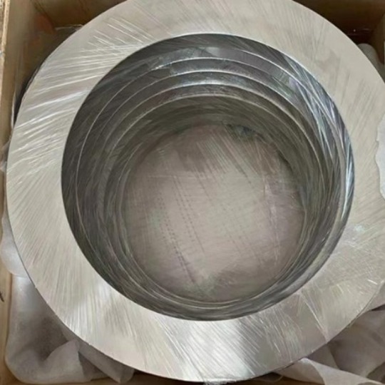
Titanium ring, titanium alloy ring, titanium alloy forgings
1, product name: titanium ring, titanium alloy ring, titanium alloy forgings
2. Material
Domestic :TA1, TA2, TA3, TA4, TA9, TA10, TC4
Us standard :GR1, GR2, GR3, GR4, GR5, GR7, GR11, GR12, GR23;
National standard :GB/T16598-1996
Us standard :ASTM B348, ASTM B381, AMS 4928
3. Specifications
Outer diameter φ(200~400)* Inner diameter φ(100~300)* Height (20~120)
Outer diameter φ400 ~700 * Inner diameter φ4(150~500)* Height (40~250)
Outer diameter φ700 ~1500 * Inner diameter φ300 ~1200 * Height (40~600)
4. Production process
Forging, die forging, rotary forging, precision forging, welding testing tensile strength testing, hardness testing, chemical composition testing, ultrasonic testing, X-ray testing, penetration coloring testing. Surface treatment: finish, chamfer. Surface quality: The surface roughness Ra value of the two end faces should be no more than 3.2lum(subject to ultrasonic inspection requirements), the surface roughness Ra of the inner and outer surfaces should be no more than 12.5um(Ra should be no more than 3.2um when ultrasonic inspection is required for the outer circumferential surface), and the chamfer radius should be 5~15mm.
#Aerospace , #Defense , #Supplier , #aerospace ,#defense , #medical , #titanium, #industrial , #oil , #gas.


0 notes
Text
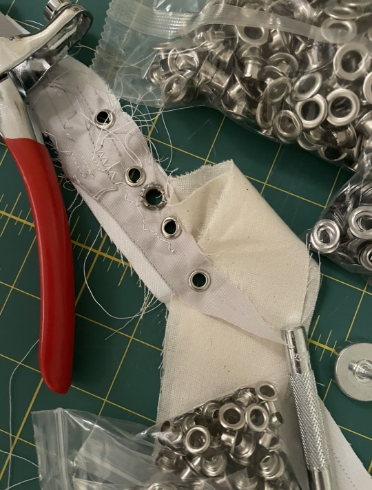
Pt. 2.5 fucking grommets
So. I did already have a grommet kit, but the grommets were gold and I wanted silver, so I was trying to find some nice silver grommets I could use last minute on December 21. As per my previous post, this was already pushing the deadline, but I was still determined to finish by the 24th, the final day before leaving for vacay. With Dritz 3/8”, I realized that the measurement number of a grommet is only the inner diameter, not counting the outer ring. This meant they were way too fucking big, by far, for my corset. This is when I caved to using Amazon Prime, but you’d be surprised by the sheer impossibility of finding silver grommets with a diameter <1/2”, even on Amazon. Eventually I picked out the smallest I could find that also came with setting pliers because I wasn’t sure if my own grommet setting tool set would be the right size. I got dddddd and when they arrived I was like yay!! clearly everything’s good right? :D and then immediately noticed the slits on the part that gets clamped down onto the washer. And then read the instructions that clearly showed how those slits would create a flower like backing with the metal splayed out from the center. And then I did a test on a scrap of sateen, 2 layers of muslin (for extra durability when lacing the corset), and coutil to see how it would look.
://
now see, everything worked as it said it was, but that meant I would most definitely have raw(?) metal poking into any undergarment layer worn under the corset, and those unfiled edges could scrap against the undergarment and possibly fray or tear it, or I would be hyeraware of feeling those edges scraping against my own skin even through an undergarment. Also I just hated it texturally and visually, so I was dying inside >://// AND, it was still a little too big, because it could only just barely fit inside 1/2”— counting the outer metal edge— and I hated it because I wanted there to still be a little gap between the boning channels and the outer edge of the grommet. I still tried to convince my perfectionist brain that this was a totally acceptable option, all while knowing I would still hate it eternally, but not having a choice because it was way to late to try and find anything smaller that also didn’t have those slits in the grommet.
luckily(?) I was persuaded on the night of the 24th that there was literally no way I could get the entire corset finished in time to leave the next day, so I finally gave in and hunted through a shitton of Etsy sellers until I found 5AHachiHouses. Like straight up I looked for legit hours if not days just to find them. The ones I got were silver, 4.5 mm “outside” (actually the inner hole’s diameter), and 8 mm diameter from outer edge to outer edge. They have a lovely selection of what I would lovingly call “specialty grommets” for the range in very specific sizes and colors. However, when I placed my purchase, I forgot to look for a setting tool for the size I ordered, but still thought that I could use the two I did have. The order arrived in January and I was very pleased to see that they would fit, but quickly realized after a few tests with the tools I did have that they warped the grommet when set. SO, I went back to the sellers Etsy, tried to find a setting tool, and realized that they didn’t sell any setting tools, which I won’t lie is pretty fucking weird considering how rare some of the sizes they sold were. After that, I just worked on other parts of the corset because I pick fight or ✨flight✨ and was actually busy with new classes, until I got myself to go through Amazon again. I settled on getting a 2pc setting tool that was labeled as being for 5 mm size grommets, which was still like, the slightest bit bigger than the ones I had, but again, the size was so rare that there was no way I was going to find a tool that would specifically set 4.5 mm grommets. So finally, in early February, I had everything I needed.
.
.
.
AHAHAHA NO BECAUSE LIFE IS NEVER THAT EASY FOR ME, I forgot about getting a hammer. The one I previously used for the stamps had this rlly gross residue stuck to the handle, and I was not about to set 22 grommets while handling the corset-which-can’t-be-washed with shit like that on my hands or inefficiently wash my hands +22 times repeatedly, so ✨no hammer available✨
perhaps fate decided to throw me a bone, because a few days later, while cooking, I remembered that we had a metal mallet for tenderizing meat. And what do you know, one side is nice and smooth— perfect for hammering. So I pulled an absolutely unhinged idea, which was to hog the mallet for at least a month from ~February to March 18, even though I only took 6 days of actually using it right at the end, which also meant no panko-breaded chicken strips lol. Anyways here are my final test pieces from February 14th, which as you can see, from top of the strip to the bottom, it’s 4.5 mm set with 1/2” setting pliers, 4.5 mm set with 1/2” again because I was delulu enough to think I could make it work even with a prior failure made not even a minute ago, 1/2” set with 1/2” pliers but accidentally put the backing facing outwards instead of showing on the coutil side, 4.5 mm set with “1” 2pc grommet setting tool, and 4.5 mm set with 5 mm 2pc grommet setting tool (as seen in pic 1 & 3)


1 note
·
View note
Video
youtube
Ultrasonic Testing of Carbon Steel Pipe
The ultrasonic probe to be completed by the power of sound energy between each other and transform the physical characteristics of ultrasonic waves in an elastic click here medium to convey when the pipe ultrasonic flaw detection principle foundation.
The ultrasonic probe to be completed by the power of sound energy between each other and transform the physical characteristics of ultrasonic waves in an elastic medium to convey when the carbon steel pipe ultrasonic flaw detection principle foundation. Experiencing disadvantage emitted ultrasonic beam directed to convey in a tube, reflecting both the occurrence of waves and wave attenuation occurs. After signal processing flaw detector, such as the selection reflection detection, echo signal can be obtained shortcomings, such as the use penetration testing method can be achieved by virtue of shortcomings signal attenuation through the waves. Both can give quantitative shortcomings indicated by the instrument.
Using the principle of electromagnetic induction or piezoelectric effect can stimulate the inner tube is not the same type of ultrasound. Thus, the piezoelectric ultrasonic and electromagnetic ultrasonic carbon steel pipe can be used for ultrasonic inspection. But EMAT only for ferromagnetic materials.
Selection of shear (or plate wave) reflection method (or penetration method) in the probe and the pipe relative movement active state inspection, as long as the special large-diameter pipe inspection technology can be conducted. Should take the initiative to check the time or skill to ensure that the beam tube full scan appearance.
Such inspection shortcomings longitudinal beam conveyed in the tube wall along the circumferential direction; disadvantage when checking lateral beam conveyed in the wall along the tube axis. Longitudinal and transverse defects inspection should be carried out in two opposite directions of the tube.When the demand side did not make identification lateral side only drawback for inspection longitudinal shortcomings. Endorsed by both sides to negotiate, longitudinal and transverse defects inspection can be carried out only in one direction of the mild steel pipe. Choose a good coupling active or craft examining them, and not detract from the appearance of the pipe coupling medium.
1 note
·
View note
Photo

Best Regards
Why Should We Refuse Newton Theory Of The Sun Gravity
Shortly
The sun does NOT really create a gravitational field- Newton is wrong and also Einstein- let's prove that in details
Proof No. (1)
(1)
Newton gravitation equation is wrong because the planets order disproves it
Where
The gravitation equation tells (more mass necessitates shorter distance) – if this is a fact- Jupiter should be the most near planet to the sun (NOT FACT)
Also
The planets order gives no reference to the mass effect – instead – it refers to the diameter effect! and also shows a great mystery- let's see the order in following
The inner planets order
I can prove that Mars original orbit was between Mercury and Venus – the order is
(Mercury – Mars- Venus- Earth)- the planets are in order where greater diameter (and mass) necessitates LONGER orbital distance
The outer planets order
(Jupiter – Saturn – Uranus – Neptune – Pluto)
The order tells greater diameter (and not mass) necessitates shorter distances
The outer planets order is reflected on the inner – I have interesting explanation but it's our point here
The previous analysis gives 2 results
(first result) the planets order disproves Newton gravitation equation
(Second result) the planets order depends on another reason different from the planets masses
Notice
We follow the gravitation equation – for that we don't search now about the planets order reason- instead – we go together and meet a physicist with one question asks (why does NOT the planets order follow the gravitation equation?)
The physicist answers (because of The Planets Initial Conditions)
Do you see that? the physicist could find no answer (where the planets order disproves clearly the gravitation equation)- for that- he has to tell this wrong answer (Initial Conditions)-
Shortly
The physicist tells – as a result for the planet creation and (its initial conditions) the planet orbital distance doesn't follow the gravitation equation.
The next question is a very simple one (How Is The Planet Created?)
Briefly
How can we be sure of the answer (Initial Conditions)?
(2)
(how is the planet created?)
We should analyze the planet creation process because the physicist uses it as a cover for the wrong gravitation equation
Shortly
(How is the planet created?)- the book tells (by random process, initial conditions and unknown historical factors)
By that–the physicist told the lies (Because of the initial conditions the planets orbital distances don't follow the gravitation equation) – this is lies because (the gravitation equation is wrong equation) but we should disprove (the initial conditions claim)
Again
(How Is The Planet Data Created?) based on exact equations – means –
No one data is effected by any initial condition, random process nor unknown factors
Means
Planet orbital distance, velocity, period, inclination, rotation period and also planet diameter and mass –all this data depends on exact equations –why??
The industry of the airplanes and rockets can help us
The manufactures needs exact equations to define this airplane length, width, weight and all data otherwise the airplane can't fly safely
Similar to that- the planet all data have to depend on exact equations otherwise this planet can't move safely –
This analysis disproves the physicist claim (the initial conditions claim)
But
I need to make this fact to be so clear because it disproves the gravitation equation
For that I have discovered an equation predicts each planet orbital distance
Which is my first equation (d^2= 4d0(d-d0)) –where (d= planet orbital distance) and (d0= its neighbor planet orbital distance) – the equation is used by two neighbor planets- I put the tests of this equation in the discussion as a reference –
NOTICE – I don't use the forma (2d0=d) it's a wrong one but we I use (d-2d0)^2=0
My first equation defines all planets orbital distances sufficiently
And it proves each planet orbital distance depends on its neighbor orbital distance –
And NO MASS BE USED
I wish- I make my idea so clear –
You told Newton is correct and the sun creates a gravitational field causes the planets motions –
My answer – I refuted Newton gravitation equation and provided another equation defines each planet orbital distance and proves it depends on its neighbor distance and not on any mass
Notice
I have five equations by which all planets data can be concluded theoretically (not only the orbital distance)- I insert my five equations in the discussion as reference
All that I did – for what reason???
I try to prove that no initial conditions effect on any planet orbital distance neither on any single data of the whole solar system- on the contrary – the solar system all data depends on exact equations –
Shortly
By using one data ONLY(Mercury orbital distance= 57.9 million km) and by my five equations-I can conclude all planets orbital distances, periods, velocities, inclinations, Diameters, masses, rotation periods and axial tilts theoretically without observation-
That proves the data depends on exact equations and no initials conditions is effective
Let's provide another proof
Proof No. (2)
Does The Sun Have A Massive Gravity?
The sun rotation period at equator =25.4 days
The sun rotation period at poles =34.4 days
The sun gravity is so weak and doesn't enable the sun to rotate in one period as the planets do – this data disproves Newton imaginary idea tells the sun has massive gravity
Notice
I don't disprove the mass gravity force – I disprove the SUN mass gravity force
Proof No. (3)
Now let's discuss your idea tells all planets revolve around their parents and even the satellites and moons
Now- if the motion is typical you can't claim to depend on the sun-
Shortly
The elliptical form of motion is the result of the Earth motion effect on our vision –
But
The planets motions be unified into one motion – by that – the Earth effect on our vision is similar to any other planet – means if you be in any place in the solar system you will see the elliptical form of motions because the effect is one where the solar planets motions be unified into one motion which creates this effect.
THE DISCUSSION
Newton theory of the sun gravity is wrong logically because the planet moves by its creation force - means – the planet creation and motion is done by one force
Otherwise the planet will be broken by effect of two force on it
Means
The planet creation process should refer to its motion reason
If I write my theory directly be as following
(the solar system is one light beam and the planets are geometrical points on it) and
The planets move by this light beam motion
This idea shows that the planet creation reason is the same reason of its motion- that also explains why the planets data depend on exact equations.
Notice
The planets are similar to gears in one machine of gears – that explains why the machine produces one motion by using different moving gears.
Thanks a lot for your kind interest and help
Speed Of Light Has An Effect On Matter Creation Process
https://www.academia.edu/s/053a0a794e
or
https://www.academia.edu/98508585/Speed_Of_Light_Has_An_Effect_On_Matter_Creation_Process
or
https://app.box.com/s/tpl1shsi2m28dqo6rq6x6j7ncid0zl4g
or
https://app.box.com/s/x52am353v74fwieeodg4a73yv9c31l2r
Gerges Francis Tawdrous +201022532292
Physics Department- Physics & Mathematics Faculty
Peoples' Friendship university of Russia – Moscow (2010-2013)
Curriculum Vitae https://www.academia.edu/s/b88b0ecb7c
E-mail [email protected], [email protected]
ORCID https://orcid.org/0000-0002-1041-7147
Facebook https://www.facebook.com/gergis.tawadrous
VK https://vk.com/id696655587
Tumblr https://www.tumblr.com/blog/itsgerges
Researcherid https://publons.com/researcher/3510834/gerges-tawadrous/
Google https://scholar.google.com/citations?user=2Y4ZdTUAAAAJ&hl=en
Livejournal https://gerges2022.livejournal.com/profile
Pocket https://getpocket.com/@646g8dZ0p3aX5Ad1bsTr4d9THjA5p6a5b2fX99zd54g221E4bs76eBdtf6aJw5d0?src=navbar
PUBLICATIONS
box https://app.box.com/s/47fwd0gshir636xt0i3wpso8lvvl8vnv
Academia https://rudn.academia.edu/GergesTawadrous
List of publications http://vixra.org/author/gerges_francis_tawdrous
Slideshare
https://www.slideshare.net/Gergesfrancis
#astrophysics#quantum physics#physique#physics#mathematics#maths#Astronomy#astronomia#русский tumblr#quantum mechanics#science side of tumblr#geometry#engineering#Геометрия#геометри#инженерия#инженери#астрономи Космос Наука#Наука#Наук#математика#математик#математический анализ#математический#космология#космолог#космоло#астрономия#астрономи#квантовая физика
2 notes
·
View notes
Photo

Polarized X-rays reveal shape, orientation of extremely hot matter around black hole Researchers’ recent observations of a stellar-mass black hole called Cygnus X-1 reveal new details about the configuration of extremely hot matter in the region immediately surrounding the black hole. Matter is heated to millions of degrees as it is pulled toward a black hole. This hot matter glows in X-rays. Researchers are using measurements of the polarization of these X-rays to test and refine models that describe how black holes swallow matter, becoming some of the most luminous sources of light — including X-rays — in the universe. The new measurements from Cygnus X-1, published online by the journal Science on Thursday, Nov. 3, represent the first observations of a mass-accreting black hole from the Imaging X-Ray Polarimetry Explorer (IXPE) mission, an international collaboration between NASA and the Italian Space Agency (ASI). Cygnus X-1 is one of the brightest X-ray sources in our galaxy, consisting of a 21 solar mass black hole in orbit with a 41 solar mass companion star. “Previous X-ray observations of black holes only measured the arrival direction, arrival time and energy of the X-rays from hot plasma spiraling toward the black holes,” said lead author Henric Krawczynski, the Wayman Crow Professor of Physics in Arts & Sciences at Washington University in St. Louis and a faculty fellow in the university’s McDonnell Center for the Space Sciences. “IXPE also measures their linear polarization, which carries information about how the X-rays were emitted — and if, and where, they scatter off material close to the black hole.” No light, not even light from X-rays, can escape from inside the event horizon of a black hole. The X-rays detected with IXPE are emitted by the hot matter, or plasma, in a 2,000-km diameter region surrounding the 60-km diameter event horizon of the black hole. Combining the IXPE data with concurrent observations from NASA’s NICER and NuSTAR X-ray observatories in May and June 2022 allowed the authors to constrain the geometry — i.e., shape and location — of the plasma. The researchers found that the plasma extends perpendicular to a two-sided, pencil-shaped plasma outflow, or jet, imaged in earlier radio observations. The alignment of the direction of the X-ray polarization and the jet lends strong support to the hypothesis that the processes in the X-ray bright region close to the black hole play a crucial role in launching the jet. The observations match models predicting that the corona of hot plasma either sandwiches the disk of matter spiraling toward the black hole or replaces the inner portion of that disk. The new polarization data rule out models in which the black hole’s corona is a narrow plasma column or cone along the jet axis. The scientists noted that a better understanding of the geometry of the plasma around a black hole can reveal much about the inner workings of black holes and how they accrete mass. “These new insights will enable improved X-ray studies of how gravity curves space and time close to black holes,” Krawczynski said. Related to the Cygnus X-1 black hole specifically, “IXPE observations reveal that the accretion flow is seen more edge-on than previously thought,” explained co-author Michal Dovčiak at the Astronomical Institute of the Czech Academy of Sciences. “This may be a signature of a misalignment of the equatorial plane of the black hole and the orbital plane of the binary,” or the paired duo of the black hole and its companion star, clarified co-author Alexandra Veledina from the University of Turku. “The system may have acquired that misalignment when the black hole progenitor star exploded.” “The IXPE mission uses X-ray mirrors fabricated at NASA’s Marshall Space Flight Center and focal plane instrumentation provided by a collaboration of ASI, the National Institute for Astrophysics (INAF) and the National Institute for Nuclear Physics,” said co-author Fabio Muleri of INAF-IAPS. “Beyond Cygnus X-1, IXPE is being used to study a wide range of extreme X-ray sources, including mass accreting neutron stars, pulsars and pulsar wind nebulae, supernova remnants, our galactic center and active galactic nuclei. We’ve found a lot of surprises, and we’re having a lot of fun.” A second paper in the same issue of Science was led by Roberto Taverna at the University of Padova and describes the IXPE detection of highly polarized X-rays from the magnetar 4U 0142+61. “We are thrilled to be part of this new wave of scientific discovery in astrophysics,” Krawczynski said. IMAGE....An artist’s impression of the Cygnus X-1 system, with the black hole appearing in the center and its companion star on the left. New measurements from Cygnus X-1, reported Nov. 3 in the journal Science, represent the first observations of a mass-accreting black hole from the Imaging X-Ray Polarimetry Explorer (IXPE) mission, an international collaboration between NASA and the Italian Space Agency. CREDIT John Paice
4 notes
·
View notes
Text
Behind the Scenes of the Medical Gas Pipeline System
Introduction:
Have you ever wondered how hospitals deliver life-saving gases directly to patients? The answer lies in a complex, yet often unseen system: the Medical Gas Pipeline System (MGPS). This intricate network plays a critical role in patient care, ensuring a constant supply of vital gases for respiration, anesthesia, and various medical procedures. In this blog, we'll unveil the inner workings of the MGPS, exploring its components, functionality, and its significance in modern healthcare.
The Invisible Lifeline:
Imagine a network of veins and arteries coursing through a hospital, but instead of blood, they carry essential gases like oxygen, nitrous oxide, and compressed air. That's essentially what the MGPS is - a network of pipes, valves, and regulators that distribute these gases directly to patient beds, operating rooms, and intensive care units (ICUs). These gases are the silent heroes in:
Keeping patients alive: Oxygen is vital for respiration, especially for critically ill patients.
Pain management: Nitrous oxide is a key component of anesthesia, allowing patients to undergo surgeries comfortably.
Surgical procedures: Compressed air powers essential medical equipment during surgeries.
Unveiling the MGPS:
The MGPS is a marvel of engineering, comprised of several key components:
Source: Bulk gas tanks or on-site generators provide a constant supply of medical gases.
Pipeline Network: A network of copper pipes with specific diameters and materials transport the gases throughout the facility.
Alarm Systems: These constantly monitor for leaks, pressure fluctuations, and system failures, ensuring safety.
Pressure Regulators: High-pressure gas from the source is reduced to safe and usable levels for patient care by these regulators.
Outlet Points: These are strategically placed wall-mounted valves and connections where medical staff can access the gases for patient use.
Maintaining the Lifeline:
Regular maintenance of the MGPS is crucial to ensure its smooth operation and patient safety. This includes:
Leak detection and repair: Even small leaks can disrupt gas delivery and pose safety risks.
Pressure monitoring: Maintaining consistent pressure levels is essential for effective gas delivery.
System checks and inspections: Regularly testing and inspecting all components ensures the MGPS remains reliable.
By functioning flawlessly behind the scenes, the MGPS plays a vital role in modern healthcare. It's a testament to the intricate network of systems that work together to ensure patient well-being.
1 note
·
View note
Text
How does a KN95 mask achieve its high filtration efficiency?
In the ongoing battle against airborne contaminants, KN95 masks stand tall as guardians of respiratory health. But what makes them so effective in filtering out harmful particles? Let's delve into the ingenious design elements that make KN95 masks a frontline defense.

Multiple Layers, Maximum Protection: At the heart of a KN95 mask lies a multilayered structure, meticulously crafted to trap even the tiniest of particles. Typically, these masks consist of four layers, each serving a specific purpose in the filtration process.
Spunbond Non-Woven Fabric: The outermost layer, often made of spunbond non-woven fabric, acts as a barrier against large droplets and splashes. This hydrophobic layer repels moisture, ensuring that external contaminants do not penetrate the mask.
Melt-Blown Fabric: Moving inward, the next layer comprises melt-blown fabric—a key component responsible for the mask's exceptional filtration efficiency. Through a process of extrusion and stretching, this layer forms a dense web of microscopic fibers, creating a labyrinthine network that captures particles as they attempt to pass through.
Electrostatic Charge: What sets KN95 masks apart is the electrostatic charge infused within the melt-blown fabric. This charge acts as a powerful magnet, attracting and trapping even the smallest airborne particles, including viruses and bacteria. The electrostatic effect enhances filtration efficiency, making KN95 masks highly effective in filtering out contaminants.
Hot Air Cotton Layer: Beneath the melt-blown fabric lies a hot air cotton layer, designed to provide structure and durability to the mask while also offering additional filtration. This layer further enhances breathability, ensuring comfort even during extended wear.

Skin-Friendly Inner Layer: The innermost layer, in direct contact with the wearer's skin, is crafted from soft, skin-friendly fabric. This ensures comfort and reduces irritation, allowing users to wear the mask for extended periods without discomfort.
Tight-Fitting Seal: Beyond its layered construction, the effectiveness of a KN95 mask hinges on its ability to form a tight-fitting seal around the wearer's face. A snug fit minimizes leakage, ensuring that air passes through the filtration layers rather than bypassing them. This seal is often achieved through the use of adjustable nose clips and elastic ear loops, providing a customized fit for optimal protection.
Certification and Standards: Crucially, KN95 masks undergo rigorous testing and certification to meet stringent standards set by regulatory bodies. These standards ensure that the masks deliver the level of filtration efficiency and breathability required for effective respiratory protection. When purchasing KN95 masks, it's essential to look for certifications from reputable organizations, such as the FDA or CE.
Particle Size Efficiency: KN95 masks are specifically designed to filter out particles with a diameter of 0.3 microns or larger. This includes a wide range of contaminants, including dust, pollen, mold spores, and most importantly, respiratory droplets carrying viruses such as SARS-CoV-2. The combination of mechanical filtration and electrostatic attraction ensures high particle capture efficiency, offering robust protection against airborne pathogens.
Versatility and Reusability: Unlike disposable masks, KN95 masks are often reusable, provided they are properly cared for and maintained. This makes them not only cost-effective but also environmentally friendly. Regular cleaning and disinfection help preserve the integrity of the filtration layers, ensuring consistent performance over multiple uses.
In conclusion, the exceptional filtration efficiency of KN95 masks is a result of meticulous design, incorporating multiple layers of specialized materials and innovative technologies. From spunbond non-woven fabric to electrostatically charged melt-blown layers, each component plays a vital role in trapping airborne contaminants and safeguarding respiratory health. As we navigate through challenging times, KN95 face masks stand as a testament to human ingenuity in the pursuit of safety and well-being.
Stay safe, stay protected with KN95 masks—a shield against unseen threats in the air we breathe.
0 notes
Last Seen Blogs